实例介绍
【实例简介】PICMG 3.0 R3.0_Radisys
【实例截图】

【核心代码】
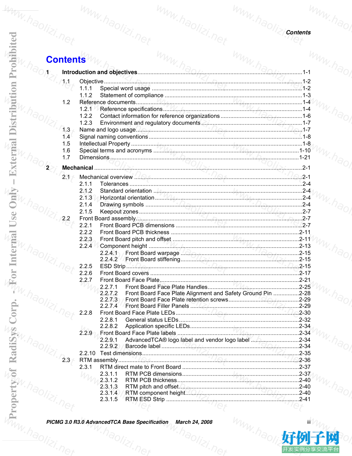
Contents
1 Introduction and objectives.......................................................................................................1-1
1.1 Objective............................................................................................................................1-2
1.1.1 Special word usage ..............................................................................................1-2
1.1.2 Statement of compliance ......................................................................................1-3
1.2 Reference documents........................................................................................................1-4
1.2.1 Reference specifications.......................................................................................1-4
1.2.2 Contact information for reference organizations...................................................1-6
1.2.3 Environment and regulatory documents...............................................................1-7
1.3 Name and logo usage........................................................................................................1-7
1.4 Signal naming conventions................................................................................................1-8
1.5 Intellectual Property...........................................................................................................1-8
1.6 Special terms and acronyms ...........................................................................................1-10
1.7 Dimensions......................................................................................................................1-21
2 Mechanical..................................................................................................................................2-1
2.1 Mechanical overview .........................................................................................................2-1
2.1.1 Tolerances............................................................................................................2-4
2.1.2 Standard orientation .............................................................................................2-4
2.1.3 Horizontal orientation............................................................................................2-4
2.1.4 Drawing symbols ..................................................................................................2-4
2.1.5 Keepout zones......................................................................................................2-7
2.2 Front Board assembly........................................................................................................2-7
2.2.1 Front Board PCB dimensions ...............................................................................2-7
2.2.2 Front Board PCB thickness ................................................................................2-11
2.2.3 Front Board pitch and offset ...............................................................................2-11
2.2.4 Component height ..............................................................................................2-13
2.2.4.1 Front Board warpage ..........................................................................2-15
2.2.4.2 Front Board stiffening..........................................................................2-15
2.2.5 ESD Strip............................................................................................................2-15
2.2.6 Front Board covers .............................................................................................2-17
2.2.7 Front Board Face Plate.......................................................................................2-21
2.2.7.1 Front Board Face Plate Handles.........................................................2-25
2.2.7.2 Front Board Face Plate Alignment and Safety Ground Pin ................2-28
2.2.7.3 Front Board Face Plate retention screws............................................2-29
2.2.7.4 Front Board Filler Panels ....................................................................2-29
2.2.8 Front Board Face Plate LEDs.............................................................................2-30
2.2.8.1 General status LEDs...........................................................................2-32
2.2.8.2 Application specific LEDs....................................................................2-34
2.2.9 Front Board Face Plate labels ............................................................................2-34
2.2.9.1 AdvancedTCA® logo label and vendor logo label ..............................2-34
2.2.9.2 Barcode label......................................................................................2-34
2.2.10 Test dimensions..................................................................................................2-35
2.3 RTM assembly.................................................................................................................2-36
2.3.1 RTM direct mate to Front Board .........................................................................2-37
2.3.1.1 RTM PCB dimensions.........................................................................2-37
2.3.1.2 RTM PCB thickness............................................................................2-40
2.3.1.3 RTM pitch and offset...........................................................................2-40
2.3.1.4 RTM component height.......................................................................2-40
2.3.1.5 RTM ESD Strip ...................................................................................2-41
Property of RadiSys Corp. - For Internal Use Only – External Distribution Prohibited
iv PICMG 3.0 R3.0 AdvancedTCA Base Specification March 24, 2008
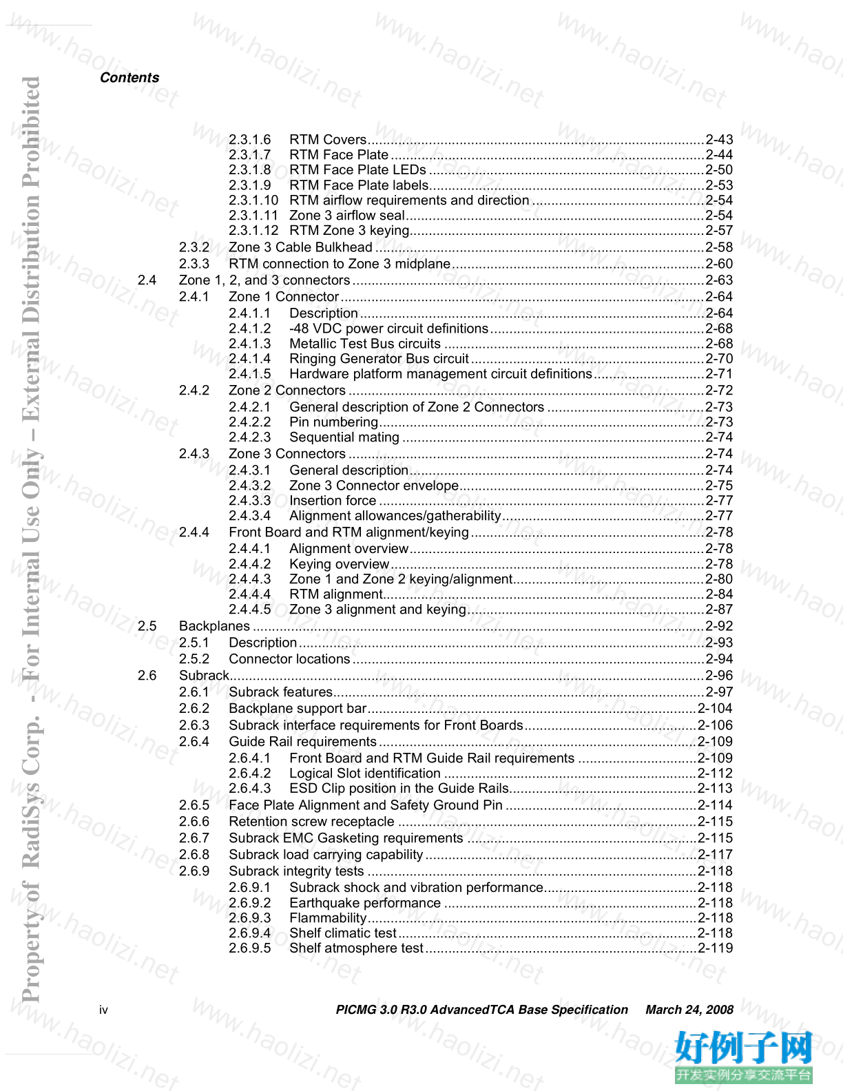
Contents
2.3.1.6 RTM Covers........................................................................................2-43
2.3.1.7 RTM Face Plate..................................................................................2-44
2.3.1.8 RTM Face Plate LEDs........................................................................2-50
2.3.1.9 RTM Face Plate labels........................................................................2-53
2.3.1.10 RTM airflow requirements and direction.............................................2-54
2.3.1.11 Zone 3 airflow seal..............................................................................2-54
2.3.1.12 RTM Zone 3 keying.............................................................................2-57
2.3.2 Zone 3 Cable Bulkhead......................................................................................2-58
2.3.3 RTM connection to Zone 3 midplane..................................................................2-60
2.4 Zone 1, 2, and 3 connectors............................................................................................2-63
2.4.1 Zone 1 Connector...............................................................................................2-64
2.4.1.1 Description..........................................................................................2-64
2.4.1.2 -48 VDC power circuit definitions........................................................2-68
2.4.1.3 Metallic Test Bus circuits ....................................................................2-68
2.4.1.4 Ringing Generator Bus circuit.............................................................2-70
2.4.1.5 Hardware platform management circuit definitions.............................2-71
2.4.2 Zone 2 Connectors.............................................................................................2-72
2.4.2.1 General description of Zone 2 Connectors.........................................2-73
2.4.2.2 Pin numbering.....................................................................................2-73
2.4.2.3 Sequential mating...............................................................................2-74
2.4.3 Zone 3 Connectors.............................................................................................2-74
2.4.3.1 General description.............................................................................2-74
2.4.3.2 Zone 3 Connector envelope................................................................2-75
2.4.3.3 Insertion force.....................................................................................2-77
2.4.3.4 Alignment allowances/gatherability.....................................................2-77
2.4.4 Front Board and RTM alignment/keying.............................................................2-78
2.4.4.1 Alignment overview.............................................................................2-78
2.4.4.2 Keying overview..................................................................................2-78
2.4.4.3 Zone 1 and Zone 2 keying/alignment..................................................2-80
2.4.4.4 RTM alignment....................................................................................2-84
2.4.4.5 Zone 3 alignment and keying..............................................................2-87
2.5 Backplanes......................................................................................................................2-92
2.5.1 Description..........................................................................................................2-93
2.5.2 Connector locations............................................................................................2-94
2.6 Subrack............................................................................................................................2-96
2.6.1 Subrack features.................................................................................................2-97
2.6.2 Backplane support bar......................................................................................2-104
2.6.3 Subrack interface requirements for Front Boards.............................................2-106
2.6.4 Guide Rail requirements...................................................................................2-109
2.6.4.1 Front Board and RTM Guide Rail requirements ...............................2-109
2.6.4.2 Logical Slot identification ..................................................................2-112
2.6.4.3 ESD Clip position in the Guide Rails.................................................2-113
2.6.5 Face Plate Alignment and Safety Ground Pin..................................................2-114
2.6.6 Retention screw receptacle ..............................................................................2-115
2.6.7 Subrack EMC Gasketing requirements ............................................................2-115
2.6.8 Subrack load carrying capability.......................................................................2-117
2.6.9 Subrack integrity tests ......................................................................................2-118
2.6.9.1 Subrack shock and vibration performance........................................2-118
2.6.9.2 Earthquake performance ..................................................................2-118
2.6.9.3 Flammability......................................................................................2-118
2.6.9.4 Shelf climatic test..............................................................................2-118
2.6.9.5 Shelf atmosphere test.......................................................................2-119
Property of RadiSys Corp. - For Internal Use Only – External Distribution Prohibited
PICMG 3.0 R3.0 AdvancedTCA Base Specification March 24, 2008 v
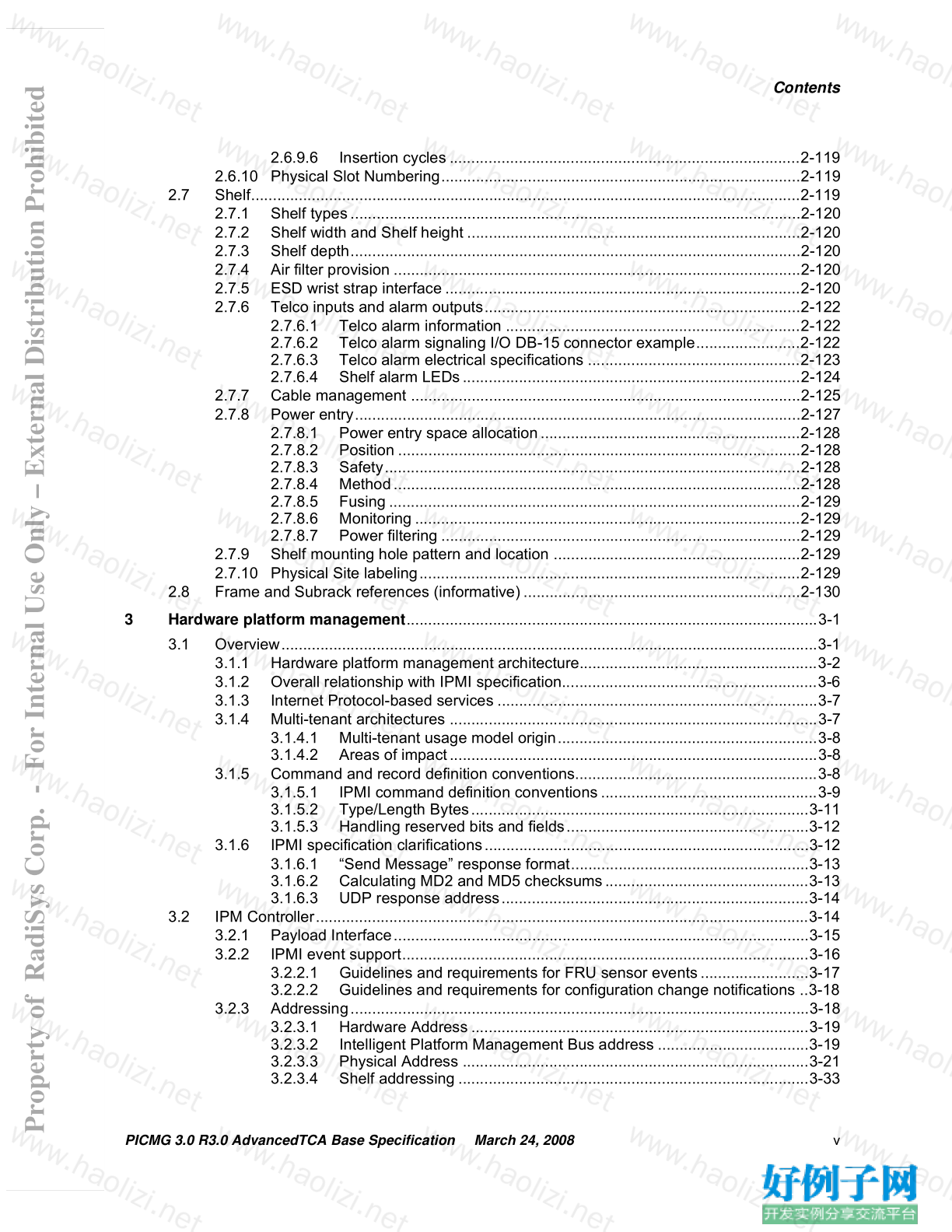
Contents
2.6.9.6 Insertion cycles .................................................................................2-119
2.6.10 Physical Slot Numbering...................................................................................2-119
2.7 Shelf...............................................................................................................................2-119
2.7.1 Shelf types........................................................................................................2-120
2.7.2 Shelf width and Shelf height .............................................................................2-120
2.7.3 Shelf depth........................................................................................................2-120
2.7.4 Air filter provision ..............................................................................................2-120
2.7.5 ESD wrist strap interface ..................................................................................2-120
2.7.6 Telco inputs and alarm outputs.........................................................................2-122
2.7.6.1 Telco alarm information ....................................................................2-122
2.7.6.2 Telco alarm signaling I/O DB-15 connector example........................2-122
2.7.6.3 Telco alarm electrical specifications .................................................2-123
2.7.6.4 Shelf alarm LEDs..............................................................................2-124
2.7.7 Cable management ..........................................................................................2-125
2.7.8 Power entry.......................................................................................................2-127
2.7.8.1 Power entry space allocation............................................................2-128
2.7.8.2 Position .............................................................................................2-128
2.7.8.3 Safety................................................................................................2-128
2.7.8.4 Method..............................................................................................2-128
2.7.8.5 Fusing ...............................................................................................2-129
2.7.8.6 Monitoring .........................................................................................2-129
2.7.8.7 Power filtering ...................................................................................2-129
2.7.9 Shelf mounting hole pattern and location .........................................................2-129
2.7.10 Physical Site labeling........................................................................................2-129
2.8 Frame and Subrack references (informative)................................................................2-130
3 Hardware platform management...............................................................................................3-1
3.1 Overview............................................................................................................................3-1
3.1.1 Hardware platform management architecture.......................................................3-2
3.1.2 Overall relationship with IPMI specification...........................................................3-6
3.1.3 Internet Protocol-based services ..........................................................................3-7
3.1.4 Multi-tenant architectures .....................................................................................3-7
3.1.4.1 Multi-tenant usage model origin............................................................3-8
3.1.4.2 Areas of impact.....................................................................................3-8
3.1.5 Command and record definition conventions........................................................3-8
3.1.5.1 IPMI command definition conventions ..................................................3-9
3.1.5.2 Type/Length Bytes..............................................................................3-11
3.1.5.3 Handling reserved bits and fields........................................................3-12
3.1.6 IPMI specification clarifications...........................................................................3-12
3.1.6.1 “Send Message” response format.......................................................3-13
3.1.6.2 Calculating MD2 and MD5 checksums...............................................3-13
3.1.6.3 UDP response address.......................................................................3-14
3.2 IPM Controller..................................................................................................................3-14
3.2.1 Payload Interface................................................................................................3-15
3.2.2 IPMI event support..............................................................................................3-16
3.2.2.1 Guidelines and requirements for FRU sensor events.........................3-17
3.2.2.2 Guidelines and requirements for configuration change notifications ..3-18
3.2.3 Addressing..........................................................................................................3-18
3.2.3.1 Hardware Address ..............................................................................3-19
3.2.3.2 Intelligent Platform Management Bus address ...................................3-19
3.2.3.3 Physical Address ................................................................................3-21
3.2.3.4 Shelf addressing .................................................................................3-33
Property of RadiSys Corp. - For Internal Use Only – External Distribution Prohibited
vi PICMG 3.0 R3.0 AdvancedTCA Base Specification March 24, 2008
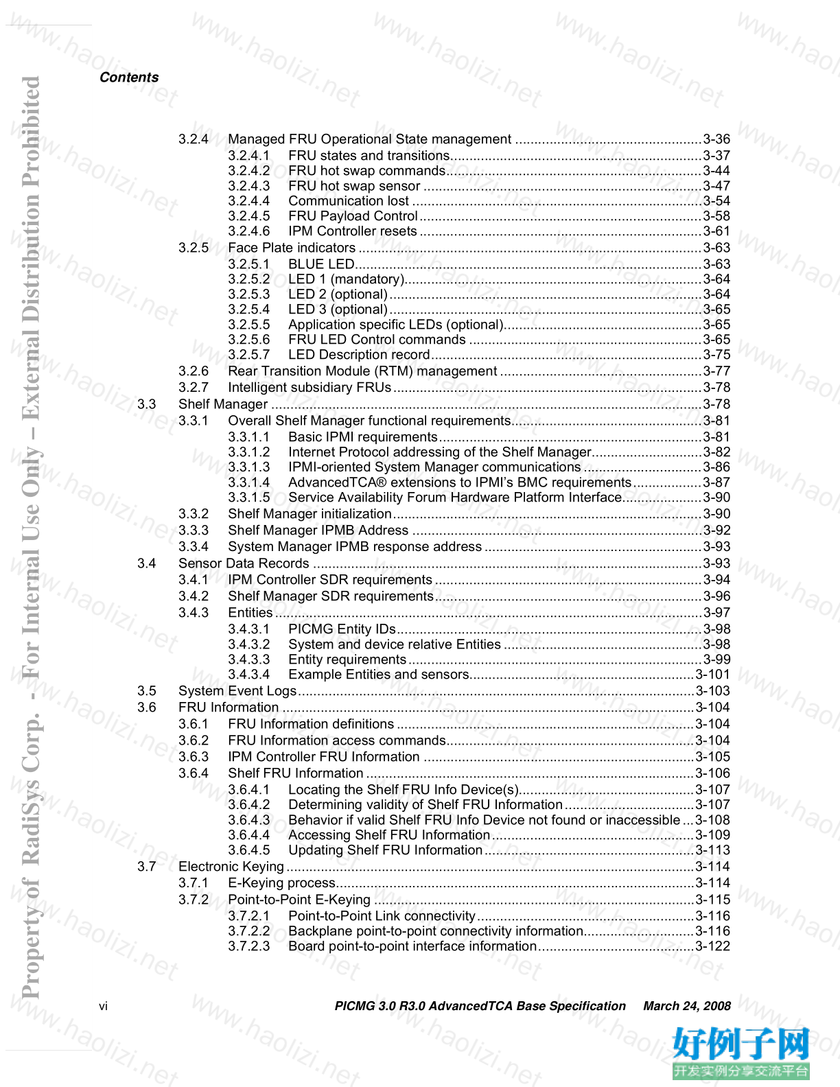
Contents
3.2.4 Managed FRU Operational State management .................................................3-36
3.2.4.1 FRU states and transitions..................................................................3-37
3.2.4.2 FRU hot swap commands...................................................................3-44
3.2.4.3 FRU hot swap sensor .........................................................................3-47
3.2.4.4 Communication lost ............................................................................3-54
3.2.4.5 FRU Payload Control..........................................................................3-58
3.2.4.6 IPM Controller resets..........................................................................3-61
3.2.5 Face Plate indicators..........................................................................................3-63
3.2.5.1 BLUE LED...........................................................................................3-63
3.2.5.2 LED 1 (mandatory)..............................................................................3-64
3.2.5.3 LED 2 (optional)..................................................................................3-64
3.2.5.4 LED 3 (optional)..................................................................................3-65
3.2.5.5 Application specific LEDs (optional)....................................................3-65
3.2.5.6 FRU LED Control commands .............................................................3-65
3.2.5.7 LED Description record.......................................................................3-75
3.2.6 Rear Transition Module (RTM) management.....................................................3-77
3.2.7 Intelligent subsidiary FRUs.................................................................................3-78
3.3 Shelf Manager .................................................................................................................3-78
3.3.1 Overall Shelf Manager functional requirements..................................................3-81
3.3.1.1 Basic IPMI requirements.....................................................................3-81
3.3.1.2 Internet Protocol addressing of the Shelf Manager.............................3-82
3.3.1.3 IPMI-oriented System Manager communications...............................3-86
3.3.1.4 AdvancedTCA® extensions to IPMI’s BMC requirements..................3-87
3.3.1.5 Service Availability Forum Hardware Platform Interface.....................3-90
3.3.2 Shelf Manager initialization.................................................................................3-90
3.3.3 Shelf Manager IPMB Address ............................................................................3-92
3.3.4 System Manager IPMB response address.........................................................3-93
3.4 Sensor Data Records ......................................................................................................3-93
3.4.1 IPM Controller SDR requirements......................................................................3-94
3.4.2 Shelf Manager SDR requirements......................................................................3-96
3.4.3 Entities................................................................................................................3-97
3.4.3.1 PICMG Entity IDs................................................................................3-98
3.4.3.2 System and device relative Entities....................................................3-98
3.4.3.3 Entity requirements.............................................................................3-99
3.4.3.4 Example Entities and sensors...........................................................3-101
3.5 System Event Logs........................................................................................................3-103
3.6 FRU Information ............................................................................................................3-104
3.6.1 FRU Information definitions..............................................................................3-104
3.6.2 FRU Information access commands.................................................................3-104
3.6.3 IPM Controller FRU Information .......................................................................3-105
3.6.4 Shelf FRU Information......................................................................................3-106
3.6.4.1 Locating the Shelf FRU Info Device(s)..............................................3-107
3.6.4.2 Determining validity of Shelf FRU Information..................................3-107
3.6.4.3 Behavior if valid Shelf FRU Info Device not found or inaccessible...3-108
3.6.4.4 Accessing Shelf FRU Information.....................................................3-109
3.6.4.5 Updating Shelf FRU Information.......................................................3-113
3.7 Electronic Keying...........................................................................................................3-114
3.7.1 E-Keying process..............................................................................................3-114
3.7.2 Point-to-Point E-Keying ....................................................................................3-115
3.7.2.1 Point-to-Point Link connectivity.........................................................3-116
3.7.2.2 Backplane point-to-point connectivity information.............................3-116
3.7.2.3 Board point-to-point interface information.........................................3-122
Property of RadiSys Corp. - For Internal Use Only – External Distribution Prohibited
PICMG 3.0 R3.0 AdvancedTCA Base Specification March 24, 2008 vii
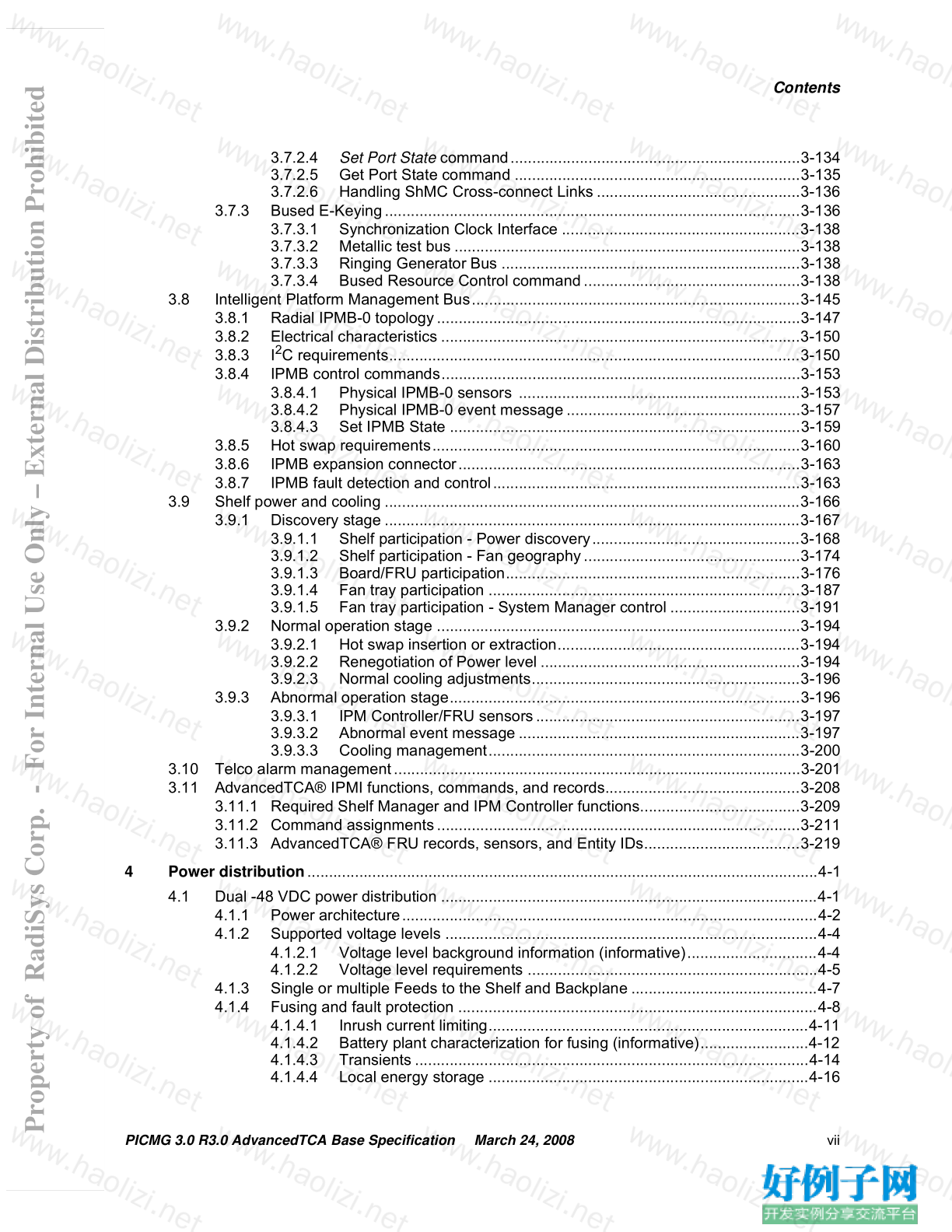
Contents
3.7.2.4 Set Port State command...................................................................3-134
3.7.2.5 Get Port State command ..................................................................3-135
3.7.2.6 Handling ShMC Cross-connect Links ...............................................3-136
3.7.3 Bused E-Keying................................................................................................3-136
3.7.3.1 Synchronization Clock Interface .......................................................3-138
3.7.3.2 Metallic test bus ................................................................................3-138
3.7.3.3 Ringing Generator Bus .....................................................................3-138
3.7.3.4 Bused Resource Control command..................................................3-138
3.8 Intelligent Platform Management Bus............................................................................3-145
3.8.1 Radial IPMB-0 topology....................................................................................3-147
3.8.2 Electrical characteristics ...................................................................................3-150
3.8.3 I 2 C requirements...............................................................................................3-150
3.8.4 IPMB control commands...................................................................................3-153
3.8.4.1 Physical IPMB-0 sensors .................................................................3-153
3.8.4.2 Physical IPMB-0 event message......................................................3-157
3.8.4.3 Set IPMB State .................................................................................3-159
3.8.5 Hot swap requirements.....................................................................................3-160
3.8.6 IPMB expansion connector...............................................................................3-163
3.8.7 IPMB fault detection and control.......................................................................3-163
3.9 Shelf power and cooling ................................................................................................3-166
3.9.1 Discovery stage ................................................................................................3-167
3.9.1.1 Shelf participation - Power discovery................................................3-168
3.9.1.2 Shelf participation - Fan geography..................................................3-174
3.9.1.3 Board/FRU participation....................................................................3-176
3.9.1.4 Fan tray participation ........................................................................3-187
3.9.1.5 Fan tray participation - System Manager control ..............................3-191
3.9.2 Normal operation stage ....................................................................................3-194
3.9.2.1 Hot swap insertion or extraction........................................................3-194
3.9.2.2 Renegotiation of Power level ............................................................3-194
3.9.2.3 Normal cooling adjustments..............................................................3-196
3.9.3 Abnormal operation stage.................................................................................3-196
3.9.3.1 IPM Controller/FRU sensors.............................................................3-197
3.9.3.2 Abnormal event message .................................................................3-197
3.9.3.3 Cooling management........................................................................3-200
3.10 Telco alarm management..............................................................................................3-201
3.11 AdvancedTCA® IPMI functions, commands, and records.............................................3-208
3.11.1 Required Shelf Manager and IPM Controller functions.....................................3-209
3.11.2 Command assignments....................................................................................3-211
3.11.3 AdvancedTCA® FRU records, sensors, and Entity IDs....................................3-219
4 Power distribution......................................................................................................................4-1
4.1 Dual -48 VDC power distribution .......................................................................................4-1
4.1.1 Power architecture................................................................................................4-2
4.1.2 Supported voltage levels ......................................................................................4-4
4.1.2.1 Voltage level background information (informative)..............................4-4
4.1.2.2 Voltage level requirements ...................................................................4-5
4.1.3 Single or multiple Feeds to the Shelf and Backplane ...........................................4-7
4.1.4 Fusing and fault protection ...................................................................................4-8
4.1.4.1 Inrush current limiting..........................................................................4-11
4.1.4.2 Battery plant characterization for fusing (informative).........................4-12
4.1.4.3 Transients ...........................................................................................4-14
4.1.4.4 Local energy storage ..........................................................................4-16
Property of RadiSys Corp. - For Internal Use Only – External Distribution Prohibited
viii PICMG 3.0 R3.0 AdvancedTCA Base Specification March 24, 2008
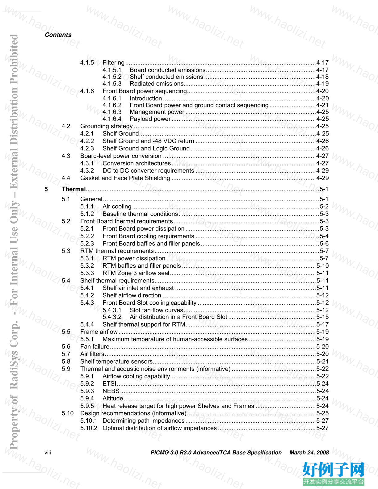
Contents
4.1.5 Filtering...............................................................................................................4-17
4.1.5.1 Board conducted emissions................................................................4-17
4.1.5.2 Shelf conducted emissions.................................................................4-18
4.1.5.3 Radiated emissions.............................................................................4-19
4.1.6 Front Board power sequencing...........................................................................4-20
4.1.6.1 Introduction.........................................................................................4-20
4.1.6.2 Front Board power and ground contact sequencing...........................4-21
4.1.6.3 Management power............................................................................4-25
4.1.6.4 Payload power....................................................................................4-25
4.2 Grounding strategy..........................................................................................................4-25
4.2.1 Shelf Ground.......................................................................................................4-25
4.2.2 Shelf Ground and -48 VDC return ......................................................................4-26
4.2.3 Shelf Ground and Logic Ground.........................................................................4-26
4.3 Board-level power conversion .........................................................................................4-27
4.3.1 Conversion architectures....................................................................................4-27
4.3.2 DC to DC converter requirements ......................................................................4-29
4.4 Gasket and Face Plate Shielding ....................................................................................4-29
5 Thermal........................................................................................................................................5-1
5.1 General..............................................................................................................................5-1
5.1.1 Air cooling.............................................................................................................5-2
5.1.2 Baseline thermal conditions..................................................................................5-3
5.2 Front Board thermal requirements.....................................................................................5-3
5.2.1 Front Board power dissipation..............................................................................5-3
5.2.2 Front Board cooling requirements ........................................................................5-4
5.2.3 Front Board baffles and filler panels.....................................................................5-6
5.3 RTM thermal requirements................................................................................................5-7
5.3.1 RTM power dissipation.........................................................................................5-7
5.3.2 RTM baffles and filler panels..............................................................................5-10
5.3.3 RTM Zone 3 airflow seal.....................................................................................5-11
5.4 Shelf thermal requirements..............................................................................................5-11
5.4.1 Shelf air inlet and exhaust ..................................................................................5-11
5.4.2 Shelf airflow direction..........................................................................................5-12
5.4.3 Front Board Slot cooling capability.....................................................................5-12
5.4.3.1 Slot fan flow curves.............................................................................5-12
5.4.3.2 Air distribution in a Front Board Slot...................................................5-15
5.4.4 Shelf thermal support for RTM............................................................................5-17
5.5 Frame airflow...................................................................................................................5-19
5.5.1 Maximum temperature of human-accessible surfaces.......................................5-19
5.6 Fan failure........................................................................................................................5-20
5.7 Air filters...........................................................................................................................5-20
5.8 Shelf temperature sensors...............................................................................................5-21
5.9 Thermal and acoustic noise environments (informative).................................................5-22
5.9.1 Airflow cooling capability.....................................................................................5-22
5.9.2 ETSI....................................................................................................................5-24
5.9.3 NEBS..................................................................................................................5-24
5.9.4 Altitude................................................................................................................5-24
5.9.5 Heat release target for high power Shelves and Frames ...................................5-24
5.10 Design recommendations (informative)...........................................................................5-25
5.10.1 Determining path impedances............................................................................5-27
5.10.2 Optimal distribution of airflow impedances.........................................................5-27
Property of RadiSys Corp. - For Internal Use Only – External Distribution Prohibited
PICMG 3.0 R3.0 AdvancedTCA Base Specification March 24, 2008 ix
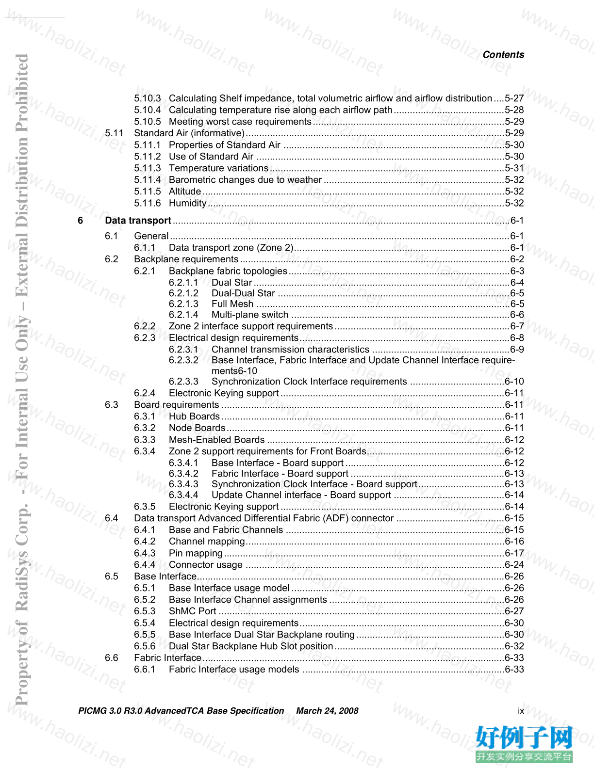
Contents
5.10.3 Calculating Shelf impedance, total volumetric airflow and airflow distribution....5-27
5.10.4 Calculating temperature rise along each airflow path.........................................5-28
5.10.5 Meeting worst case requirements.......................................................................5-29
5.11 Standard Air (informative)................................................................................................5-29
5.11.1 Properties of Standard Air ..................................................................................5-30
5.11.2 Use of Standard Air ............................................................................................5-30
5.11.3 Temperature variations.......................................................................................5-31
5.11.4 Barometric changes due to weather...................................................................5-32
5.11.5 Altitude................................................................................................................5-32
5.11.6 Humidity..............................................................................................................5-32
6 Data transport.............................................................................................................................6-1
6.1 General..............................................................................................................................6-1
6.1.1 Data transport zone (Zone 2)................................................................................6-1
6.2 Backplane requirements....................................................................................................6-2
6.2.1 Backplane fabric topologies..................................................................................6-3
6.2.1.1 Dual Star...............................................................................................6-4
6.2.1.2 Dual-Dual Star ......................................................................................6-5
6.2.1.3 Full Mesh ..............................................................................................6-5
6.2.1.4 Multi-plane switch .................................................................................6-6
6.2.2 Zone 2 interface support requirements.................................................................6-7
6.2.3 Electrical design requirements..............................................................................6-8
6.2.3.1 Channel transmission characteristics ...................................................6-9
6.2.3.2 Base Interface, Fabric Interface and Update Channel Interface require-
ments6-10
6.2.3.3 Synchronization Clock Interface requirements ...................................6-10
6.2.4 Electronic Keying support...................................................................................6-11
6.3 Board requirements .........................................................................................................6-11
6.3.1 Hub Boards.........................................................................................................6-11
6.3.2 Node Boards.......................................................................................................6-11
6.3.3 Mesh-Enabled Boards ........................................................................................6-12
6.3.4 Zone 2 support requirements for Front Boards...................................................6-12
6.3.4.1 Base Interface - Board support...........................................................6-12
6.3.4.2 Fabric Interface - Board support .........................................................6-13
6.3.4.3 Synchronization Clock Interface - Board support................................6-13
6.3.4.4 Update Channel interface - Board support .........................................6-14
6.3.5 Electronic Keying support...................................................................................6-14
6.4 Data transport Advanced Differential Fabric (ADF) connector ........................................6-15
6.4.1 Base and Fabric Channels .................................................................................6-15
6.4.2 Channel mapping................................................................................................6-16
6.4.3 Pin mapping........................................................................................................6-17
6.4.4 Connector usage ................................................................................................6-24
6.5 Base Interface..................................................................................................................6-26
6.5.1 Base Interface usage model...............................................................................6-26
6.5.2 Base Interface Channel assignments.................................................................6-26
6.5.3 ShMC Port ..........................................................................................................6-27
6.5.4 Electrical design requirements............................................................................6-30
6.5.5 Base Interface Dual Star Backplane routing.......................................................6-30
6.5.6 Dual Star Backplane Hub Slot position...............................................................6-32
6.6 Fabric Interface................................................................................................................6-33
6.6.1 Fabric Interface usage models ...........................................................................6-33
Property of RadiSys Corp. - For Internal Use Only – External Distribution Prohibited
x PICMG 3.0 R3.0 AdvancedTCA Base Specification March 24, 2008
Contents
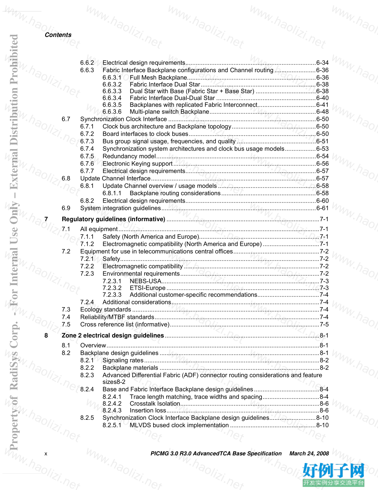
6.6.2 Electrical design requirements............................................................................6-34
6.6.3 Fabric Interface Backplane configurations and Channel routing........................6-36
6.6.3.1 Full Mesh Backplane...........................................................................6-36
6.6.3.2 Fabric Interface Dual Star...................................................................6-38
6.6.3.3 Dual Star with Base (Fabric Star Base Star) ...................................6-38
6.6.3.4 Fabric Interface Dual-Dual Star ..........................................................6-40
6.6.3.5 Backplanes with replicated Fabric Interconnect..................................6-41
6.6.3.6 Multi-plane switch Backplane..............................................................6-48
6.7 Synchronization Clock Interface......................................................................................6-50
6.7.1 Clock bus architecture and Backplane topology.................................................6-50
6.7.2 Board interfaces to clock buses..........................................................................6-50
6.7.3 Bus group signal usage, frequencies, and quality..............................................6-51
6.7.4 Synchronization system architectures and clock bus usage models..................6-53
6.7.5 Redundancy model.............................................................................................6-54
6.7.6 Electronic Keying support...................................................................................6-56
6.7.7 Electrical design requirements............................................................................6-57
6.8 Update Channel Interface................................................................................................6-57
6.8.1 Update Channel overview / usage models.........................................................6-58
6.8.1.1 Backplane routing considerations.......................................................6-58
6.8.2 Electrical design requirements............................................................................6-60
6.9 System integration guidelines..........................................................................................6-61
7 Regulatory guidelines (informative).........................................................................................7-1
7.1 All equipment.....................................................................................................................7-1
7.1.1 Safety (North America and Europe)......................................................................7-1
7.1.2 Electromagnetic compatibility (North America and Europe).................................7-1
7.2 Equipment for use in telecommunications central offices..................................................7-2
7.2.1 Safety....................................................................................................................7-2
7.2.2 Electromagnetic compatibility...............................................................................7-2
7.2.3 Environmental requirements.................................................................................7-2
7.2.3.1 NEBS-USA............................................................................................7-3
7.2.3.2 ETSI-Europe.........................................................................................7-3
7.2.3.3 Additional customer-specific recommendations....................................7-4
7.2.4 Additional considerations......................................................................................7-4
7.3 Ecology standards.............................................................................................................7-4
7.4 Reliability/MTBF standards................................................................................................7-4
7.5 Cross reference list (informative).......................................................................................7-5
8 Zone 2 electrical design guidelines..........................................................................................8-1
8.1 Overview............................................................................................................................8-1
8.2 Backplane design guidelines.............................................................................................8-1
8.2.1 Signaling rates......................................................................................................8-2
8.2.2 Backplane materials .............................................................................................8-2
8.2.3 Advanced Differential Fabric (ADF) connector routing considerations and feature
sizes8-2
8.2.4 Base and Fabric Interface Backplane design guidelines......................................8-4
8.2.4.1 Trace length matching, trace widths and spacing.................................8-4
8.2.4.2 Crosstalk Isolation.................................................................................8-6
8.2.4.3 Insertion loss.........................................................................................8-6
8.2.5 Synchronization Clock Interface Backplane design guidelines...........................8-10
8.2.5.1 MLVDS bused clock implementation..................................................8-10
Property of RadiSys Corp. - For Internal Use Only – External Distribution Prohibited
PICMG 3.0 R3.0 AdvancedTCA Base Specification March 24, 2008 xi
Contents
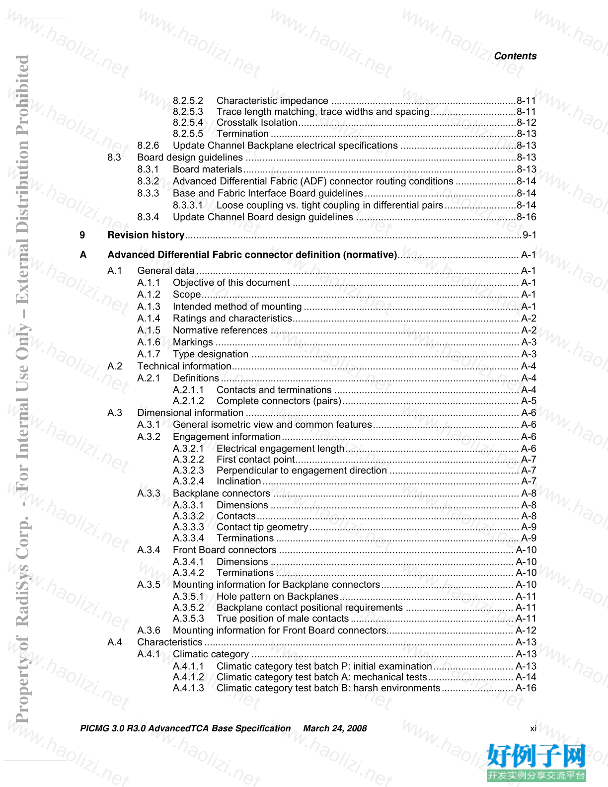
8.2.5.2 Characteristic impedance ...................................................................8-11
8.2.5.3 Trace length matching, trace widths and spacing...............................8-11
8.2.5.4 Crosstalk Isolation...............................................................................8-12
8.2.5.5 Termination.........................................................................................8-13
8.2.6 Update Channel Backplane electrical specifications ..........................................8-13
8.3 Board design guidelines ..................................................................................................8-13
8.3.1 Board materials...................................................................................................8-13
8.3.2 Advanced Differential Fabric (ADF) connector routing conditions......................8-14
8.3.3 Base and Fabric Interface Board guidelines.......................................................8-14
8.3.3.1 Loose coupling vs. tight coupling in differential pairs..........................8-14
8.3.4 Update Channel Board design guidelines ..........................................................8-16
9 Revision history..........................................................................................................................9-1
A Advanced Differential Fabric connector definition (normative)............................................ A-1
A.1 General data.....................................................................................................................A-1
A.1.1 Objective of this document .................................................................................. A-1
A.1.2 Scope................................................................................................................... A-1
A.1.3 Intended method of mounting.............................................................................. A-1
A.1.4 Ratings and characteristics.................................................................................. A-2
A.1.5 Normative references ..........................................................................................A-2
A.1.6 Markings ..............................................................................................................A-3
A.1.7 Type designation .................................................................................................A-3
A.2 Technical information........................................................................................................ A-4
A.2.1 Definitions............................................................................................................ A-4
A.2.1.1 Contacts and terminations ...................................................................A-4
A.2.1.2 Complete connectors (pairs)................................................................ A-5
A.3 Dimensional information................................................................................................... A-6
A.3.1 General isometric view and common features.....................................................A-6
A.3.2 Engagement information......................................................................................A-6
A.3.2.1 Electrical engagement length...............................................................A-6
A.3.2.2 First contact point................................................................................. A-7
A.3.2.3 Perpendicular to engagement direction ...............................................A-7
A.3.2.4 Inclination.............................................................................................A-7
A.3.3 Backplane connectors ......................................................................................... A-8
A.3.3.1 Dimensions ..........................................................................................A-8
A.3.3.2 Contacts............................................................................................... A-8
A.3.3.3 Contact tip geometry............................................................................A-9
A.3.3.4 Terminations ........................................................................................ A-9
A.3.4 Front Board connectors ..................................................................................... A-10
A.3.4.1 Dimensions ........................................................................................ A-10
A.3.4.2 Terminations ...................................................................................... A-10
A.3.5 Mounting information for Backplane connectors................................................ A-10
A.3.5.1 Hole pattern on Backplanes............................................................... A-11
A.3.5.2 Backplane contact positional requirements ....................................... A-11
A.3.5.3 True position of male contacts........................................................... A-11
A.3.6 Mounting information for Front Board connectors.............................................. A-12
A.4 Characteristics................................................................................................................ A-13
A.4.1 Climatic category ............................................................................................... A-13
A.4.1.1 Climatic category test batch P: initial examination............................. A-13
A.4.1.2 Climatic category test batch A: mechanical tests............................... A-14
A.4.1.3 Climatic category test batch B: harsh environments.......................... A-16
Property of RadiSys Corp. - For Internal Use Only – External Distribution Prohibited
xii PICMG 3.0 R3.0 AdvancedTCA Base Specification March 24, 2008
Contents
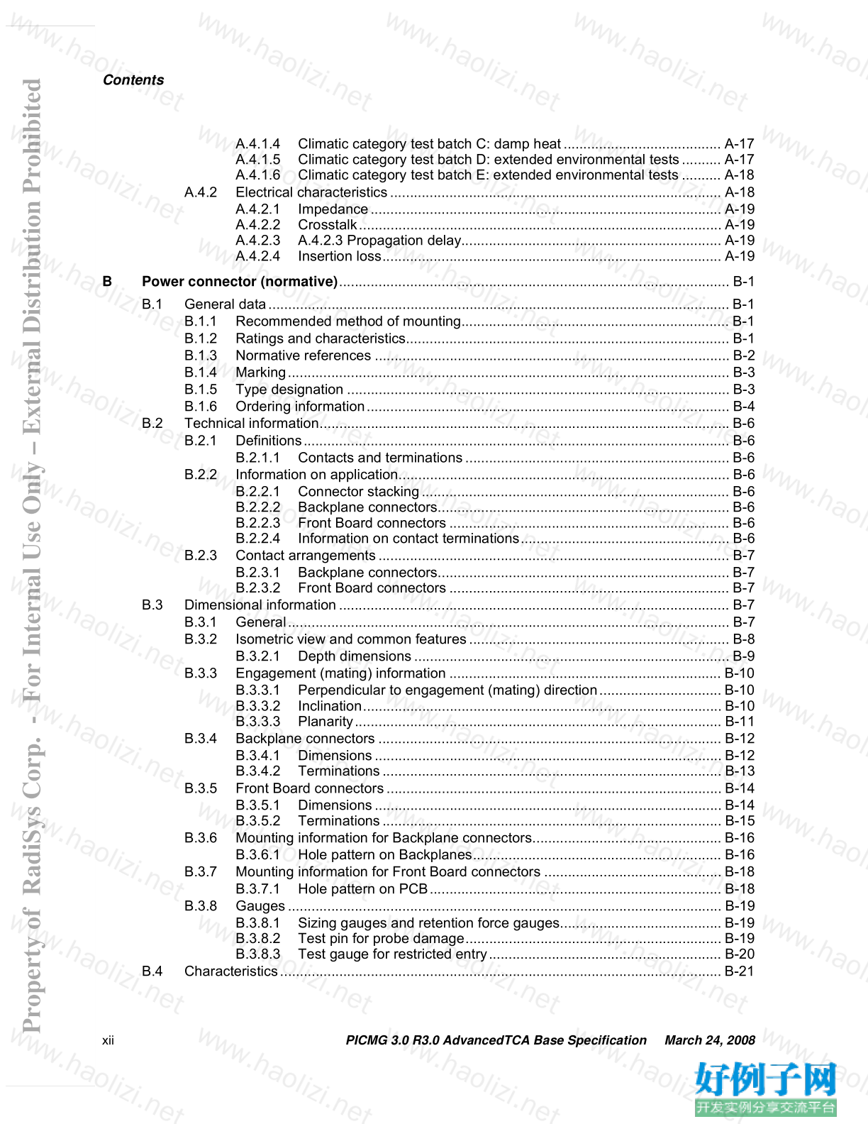
A.4.1.4 Climatic category test batch C: damp heat........................................ A-17
A.4.1.5 Climatic category test batch D: extended environmental tests.......... A-17
A.4.1.6 Climatic category test batch E: extended environmental tests .......... A-18
A.4.2 Electrical characteristics.................................................................................... A-18
A.4.2.1 Impedance......................................................................................... A-19
A.4.2.2 Crosstalk............................................................................................ A-19
A.4.2.3 A.4.2.3 Propagation delay.................................................................. A-19
A.4.2.4 Insertion loss...................................................................................... A-19
B Power connector (normative)................................................................................................... B-1
B.1 General data..................................................................................................................... B-1
B.1.1 Recommended method of mounting.................................................................... B-1
B.1.2 Ratings and characteristics.................................................................................. B-1
B.1.3 Normative references .......................................................................................... B-2
B.1.4 Marking................................................................................................................ B-3
B.1.5 Type designation ................................................................................................. B-3
B.1.6 Ordering information............................................................................................ B-4
B.2 Technical information........................................................................................................ B-6
B.2.1 Definitions............................................................................................................ B-6
B.2.1.1 Contacts and terminations................................................................... B-6
B.2.2 Information on application.................................................................................... B-6
B.2.2.1 Connector stacking.............................................................................. B-6
B.2.2.2 Backplane connectors.......................................................................... B-6
B.2.2.3 Front Board connectors ....................................................................... B-6
B.2.2.4 Information on contact terminations..................................................... B-6
B.2.3 Contact arrangements......................................................................................... B-7
B.2.3.1 Backplane connectors.......................................................................... B-7
B.2.3.2 Front Board connectors ....................................................................... B-7
B.3 Dimensional information................................................................................................... B-7
B.3.1 General................................................................................................................ B-7
B.3.2 Isometric view and common features.................................................................. B-8
B.3.2.1 Depth dimensions................................................................................ B-9
B.3.3 Engagement (mating) information ..................................................................... B-10
B.3.3.1 Perpendicular to engagement (mating) direction............................... B-10
B.3.3.2 Inclination........................................................................................... B-10
B.3.3.3 Planarity............................................................................................. B-11
B.3.4 Backplane connectors ....................................................................................... B-12
B.3.4.1 Dimensions........................................................................................ B-12
B.3.4.2 Terminations...................................................................................... B-13
B.3.5 Front Board connectors..................................................................................... B-14
B.3.5.1 Dimensions........................................................................................ B-14
B.3.5.2 Terminations...................................................................................... B-15
B.3.6 Mounting information for Backplane connectors................................................ B-16
B.3.6.1 Hole pattern on Backplanes............................................................... B-16
B.3.7 Mounting information for Front Board connectors ............................................. B-18
B.3.7.1 Hole pattern on PCB.......................................................................... B-18
B.3.8 Gauges.............................................................................................................. B-19
B.3.8.1 Sizing gauges and retention force gauges......................................... B-19
B.3.8.2 Test pin for probe damage................................................................. B-19
B.3.8.3 Test gauge for restricted entry........................................................... B-20
B.4 Characteristics................................................................................................................ B-21
Property of RadiSys Corp. - For Internal Use Only – External Distribution Prohibited
PICMG 3.0 R3.0 AdvancedTCA Base Specification March 24, 2008 xiii
Contents
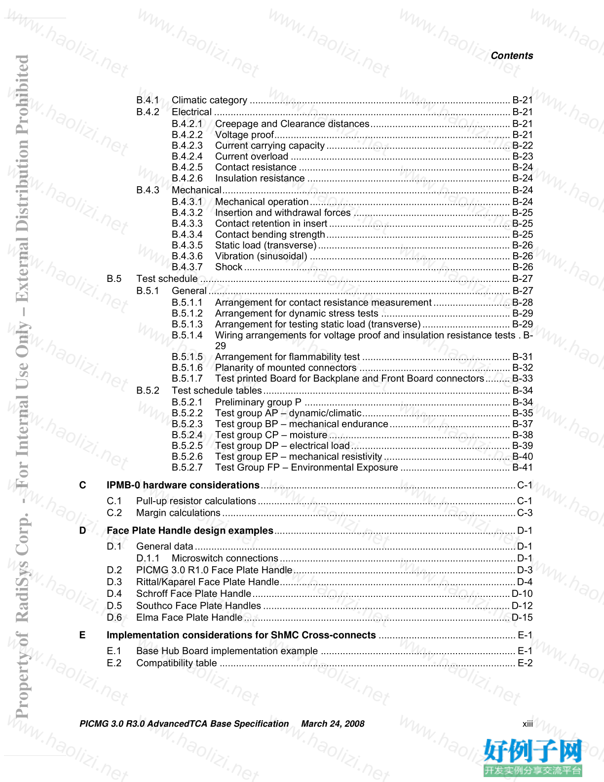
B.4.1 Climatic category ............................................................................................... B-21
B.4.2 Electrical ............................................................................................................ B-21
B.4.2.1 Creepage and Clearance distances................................................... B-21
B.4.2.2 Voltage proof...................................................................................... B-21
B.4.2.3 Current carrying capacity................................................................... B-22
B.4.2.4 Current overload ................................................................................ B-23
B.4.2.5 Contact resistance ............................................................................. B-24
B.4.2.6 Insulation resistance .......................................................................... B-24
B.4.3 Mechanical......................................................................................................... B-24
B.4.3.1 Mechanical operation......................................................................... B-24
B.4.3.2 Insertion and withdrawal forces ......................................................... B-25
B.4.3.3 Contact retention in insert.................................................................. B-25
B.4.3.4 Contact bending strength................................................................... B-25
B.4.3.5 Static load (transverse)...................................................................... B-26
B.4.3.6 Vibration (sinusoidal) ......................................................................... B-26
B.4.3.7 Shock................................................................................................. B-26
B.5 Test schedule ................................................................................................................. B-27
B.5.1 General.............................................................................................................. B-27
B.5.1.1 Arrangement for contact resistance measurement............................ B-28
B.5.1.2 Arrangement for dynamic stress tests ............................................... B-29
B.5.1.3 Arrangement for testing static load (transverse)................................ B-29
B.5.1.4 Wiring arrangements for voltage proof and insulation resistance tests . B-
29
B.5.1.5 Arrangement for flammability test ...................................................... B-31
B.5.1.6 Planarity of mounted connectors ....................................................... B-32
B.5.1.7 Test printed Board for Backplane and Front Board connectors......... B-33
B.5.2 Test schedule tables.......................................................................................... B-34
B.5.2.1 Preliminary group P ........................................................................... B-34
B.5.2.2 Test group AP – dynamic/climatic...................................................... B-35
B.5.2.3 Test group BP – mechanical endurance............................................ B-37
B.5.2.4 Test group CP – moisture.................................................................. B-38
B.5.2.5 Test group DP – electrical load.......................................................... B-39
B.5.2.6 Test group EP – mechanical resistivity.............................................. B-40
B.5.2.7 Test Group FP – Environmental Exposure ........................................ B-41
C IPMB-0 hardware considerations.............................................................................................C-1
C.1 Pull-up resistor calculations..............................................................................................C-1
C.2 Margin calculations...........................................................................................................C-3
D Face Plate Handle design examples........................................................................................D-1
D.1 General data.....................................................................................................................D-1
D.1.1 Microswitch connections......................................................................................D-1
D.2 PICMG 3.0 R1.0 Face Plate Handle.................................................................................D-3
D.3 Rittal/Kaparel Face Plate Handle......................................................................................D-4
D.4 Schroff Face Plate Handle..............................................................................................D-10
D.5 Southco Face Plate Handles..........................................................................................D-12
D.6 Elma Face Plate Handle.................................................................................................D-15
E Implementation considerations for ShMC Cross-connects ..................................................E-1
E.1 Base Hub Board implementation example ....................................................................... E-1
E.2 Compatibility table ............................................................................................................ E-2
Property of RadiSys Corp. - For Internal Use Only – External Distribution Prohibited
xiv PICMG 3.0 R3.0 AdvancedTCA Base Specification March 24, 2008
Contents
This page intentionally left blank.
Property of RadiSys Corp. - For Internal Use Only – External Distribution Prohibited
PICMG 3.0 R3.0 AdvancedTCA Base Specification March 24, 2008 xv
Contents
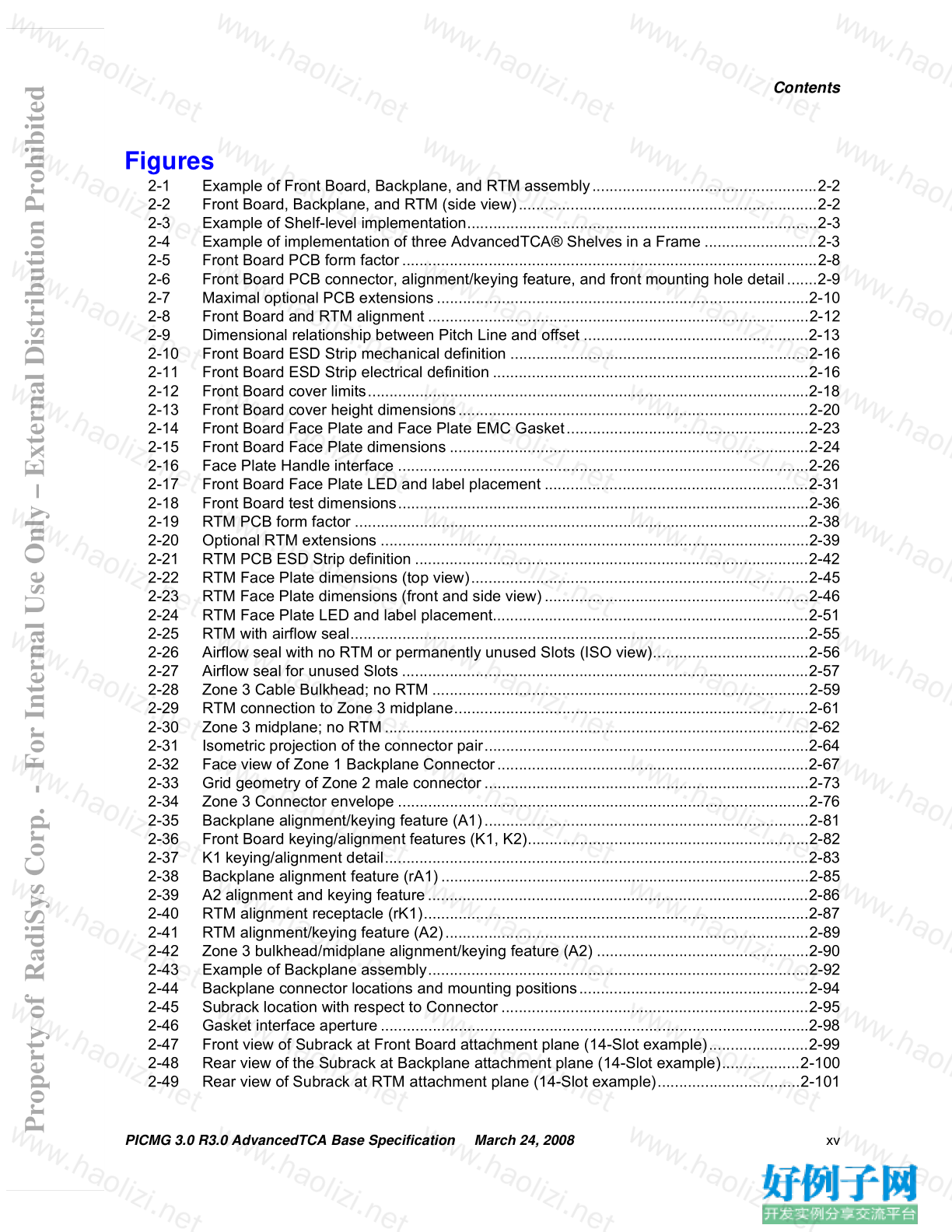
Figures
2-1 Example of Front Board, Backplane, and RTM assembly....................................................2-2
2-2 Front Board, Backplane, and RTM (side view).....................................................................2-2
2-3 Example of Shelf-level implementation.................................................................................2-3
2-4 Example of implementation of three AdvancedTCA® Shelves in a Frame ..........................2-3
2-5 Front Board PCB form factor................................................................................................2-8
2-6 Front Board PCB connector, alignment/keying feature, and front mounting hole detail.......2-9
2-7 Maximal optional PCB extensions......................................................................................2-10
2-8 Front Board and RTM alignment ........................................................................................2-12
2-9 Dimensional relationship between Pitch Line and offset ....................................................2-13
2-10 Front Board ESD Strip mechanical definition .....................................................................2-16
2-11 Front Board ESD Strip electrical definition .........................................................................2-16
2-12 Front Board cover limits......................................................................................................2-18
2-13 Front Board cover height dimensions.................................................................................2-20
2-14 Front Board Face Plate and Face Plate EMC Gasket........................................................2-23
2-15 Front Board Face Plate dimensions ...................................................................................2-24
2-16 Face Plate Handle interface ...............................................................................................2-26
2-17 Front Board Face Plate LED and label placement .............................................................2-31
2-18 Front Board test dimensions...............................................................................................2-36
2-19 RTM PCB form factor .........................................................................................................2-38
2-20 Optional RTM extensions ...................................................................................................2-39
2-21 RTM PCB ESD Strip definition ...........................................................................................2-42
2-22 RTM Face Plate dimensions (top view)..............................................................................2-45
2-23 RTM Face Plate dimensions (front and side view).............................................................2-46
2-24 RTM Face Plate LED and label placement.........................................................................2-51
2-25 RTM with airflow seal..........................................................................................................2-55
2-26 Airflow seal with no RTM or permanently unused Slots (ISO view)....................................2-56
2-27 Airflow seal for unused Slots ..............................................................................................2-57
2-28 Zone 3 Cable Bulkhead; no RTM .......................................................................................2-59
2-29 RTM connection to Zone 3 midplane..................................................................................2-61
2-30 Zone 3 midplane; no RTM..................................................................................................2-62
2-31 Isometric projection of the connector pair...........................................................................2-64
2-32 Face view of Zone 1 Backplane Connector........................................................................2-67
2-33 Grid geometry of Zone 2 male connector...........................................................................2-73
2-34 Zone 3 Connector envelope ...............................................................................................2-76
2-35 Backplane alignment/keying feature (A1)...........................................................................2-81
2-36 Front Board keying/alignment features (K1, K2).................................................................2-82
2-37 K1 keying/alignment detail..................................................................................................2-83
2-38 Backplane alignment feature (rA1).....................................................................................2-85
2-39 A2 alignment and keying feature........................................................................................2-86
2-40 RTM alignment receptacle (rK1).........................................................................................2-87
2-41 RTM alignment/keying feature (A2)....................................................................................2-89
2-42 Zone 3 bulkhead/midplane alignment/keying feature (A2) .................................................2-90
2-43 Example of Backplane assembly........................................................................................2-92
2-44 Backplane connector locations and mounting positions.....................................................2-94
2-45 Subrack location with respect to Connector .......................................................................2-95
2-46 Gasket interface aperture...................................................................................................2-98
2-47 Front view of Subrack at Front Board attachment plane (14-Slot example).......................2-99
2-48 Rear view of the Subrack at Backplane attachment plane (14-Slot example)..................2-100
2-49 Rear view of Subrack at RTM attachment plane (14-Slot example).................................2-101
Property of RadiSys Corp. - For Internal Use Only – External Distribution Prohibited
xvi PICMG 3.0 R3.0 AdvancedTCA Base Specification March 24, 2008
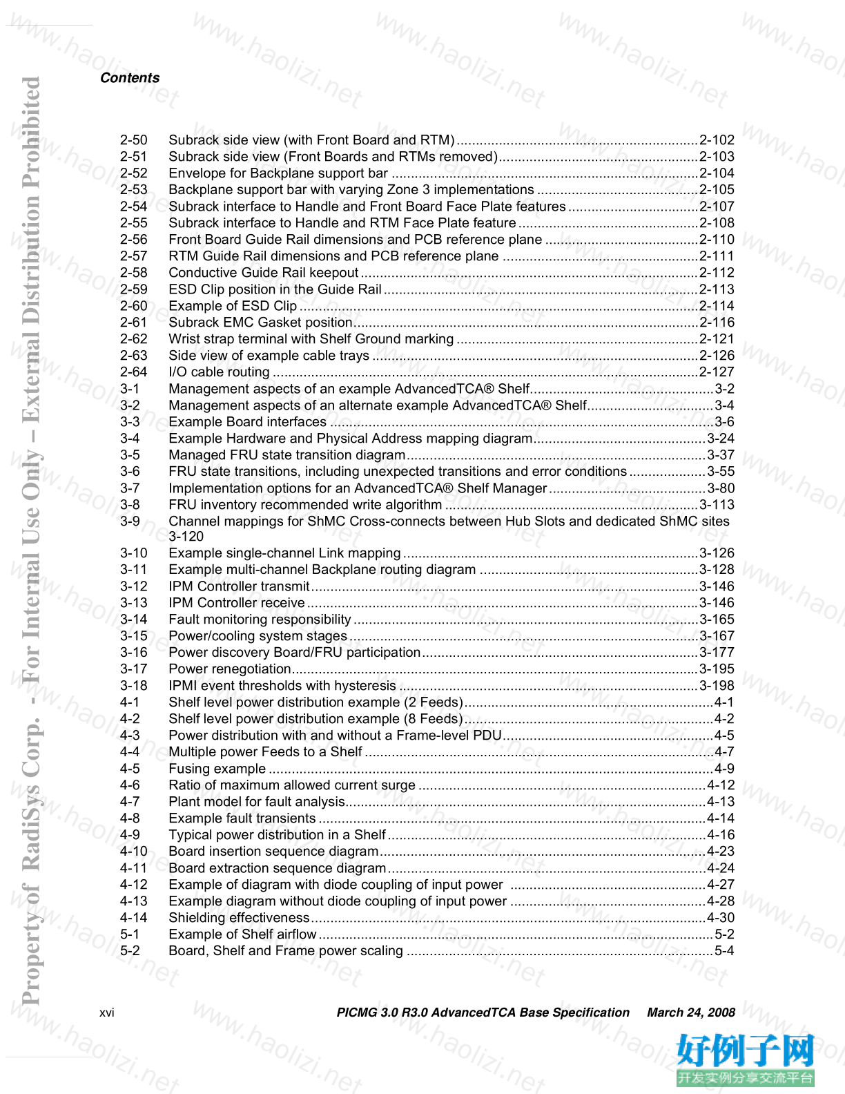
Contents
2-50 Subrack side view (with Front Board and RTM)...............................................................2-102
2-51 Subrack side view (Front Boards and RTMs removed)....................................................2-103
2-52 Envelope for Backplane support bar ................................................................................2-104
2-53 Backplane support bar with varying Zone 3 implementations..........................................2-105
2-54 Subrack interface to Handle and Front Board Face Plate features..................................2-107
2-55 Subrack interface to Handle and RTM Face Plate feature...............................................2-108
2-56 Front Board Guide Rail dimensions and PCB reference plane........................................2-110
2-57 RTM Guide Rail dimensions and PCB reference plane ...................................................2-111
2-58 Conductive Guide Rail keepout........................................................................................2-112
2-59 ESD Clip position in the Guide Rail..................................................................................2-113
2-60 Example of ESD Clip........................................................................................................2-114
2-61 Subrack EMC Gasket position..........................................................................................2-116
2-62 Wrist strap terminal with Shelf Ground marking...............................................................2-121
2-63 Side view of example cable trays.....................................................................................2-126
2-64 I/O cable routing...............................................................................................................2-127
3-1 Management aspects of an example AdvancedTCA® Shelf................................................3-2
3-2 Management aspects of an alternate example AdvancedTCA® Shelf.................................3-4
3-3 Example Board interfaces ....................................................................................................3-6
3-4 Example Hardware and Physical Address mapping diagram.............................................3-24
3-5 Managed FRU state transition diagram..............................................................................3-37
3-6 FRU state transitions, including unexpected transitions and error conditions....................3-55
3-7 Implementation options for an AdvancedTCA® Shelf Manager.........................................3-80
3-8 FRU inventory recommended write algorithm..................................................................3-113
3-9 Channel mappings for ShMC Cross-connects between Hub Slots and dedicated ShMC sites
3-120
3-10 Example single-channel Link mapping.............................................................................3-126
3-11 Example multi-channel Backplane routing diagram .........................................................3-128
3-12 IPM Controller transmit.....................................................................................................3-146
3-13 IPM Controller receive......................................................................................................3-146
3-14 Fault monitoring responsibility..........................................................................................3-165
3-15 Power/cooling system stages...........................................................................................3-167
3-16 Power discovery Board/FRU participation........................................................................3-177
3-17 Power renegotiation..........................................................................................................3-195
3-18 IPMI event thresholds with hysteresis..............................................................................3-198
4-1 Shelf level power distribution example (2 Feeds).................................................................4-1
4-2 Shelf level power distribution example (8 Feeds).................................................................4-2
4-3 Power distribution with and without a Frame-level PDU.......................................................4-5
4-4 Multiple power Feeds to a Shelf...........................................................................................4-7
4-5 Fusing example....................................................................................................................4-9
4-6 Ratio of maximum allowed current surge...........................................................................4-12
4-7 Plant model for fault analysis..............................................................................................4-13
4-8 Example fault transients.....................................................................................................4-14
4-9 Typical power distribution in a Shelf...................................................................................4-16
4-10 Board insertion sequence diagram.....................................................................................4-23
4-11 Board extraction sequence diagram...................................................................................4-24
4-12 Example of diagram with diode coupling of input power ...................................................4-27
4-13 Example diagram without diode coupling of input power ...................................................4-28
4-14 Shielding effectiveness.......................................................................................................4-30
5-1 Example of Shelf airflow.......................................................................................................5-2
5-2 Board, Shelf and Frame power scaling ................................................................................5-4
Property of RadiSys Corp. - For Internal Use Only – External Distribution Prohibited
PICMG 3.0 R3.0 AdvancedTCA Base Specification March 24, 2008 xvii
Contents
5-3 Example of Front Board cooling needs.................................................................................5-6
5-4 Example of RTM cooling needs............................................................................................5-9
5-5 Example Slot fan flow curves for Slot 1..............................................................................5-14
5-6 Inlet airflow distribution for a single Slot .............................................................................5-15
5-7 Board, Shelf, and Frame volumetric flow ................................................................................5-23
5-8 Thermal analysis process flow chart...................................................................................5-26
5-9 Example of Slot operating point..........................................................................................5-28
5-10 Temperature Rise Graphs..................................................................................................5-29
6-1 Data transport connector zone .............................................................................................6-2
6-2 Backplane.............................................................................................................................6-3
6-3 Dual Star Topology...............................................................................................................6-4
6-4 Mesh topology ......................................................................................................................6-5
6-5 3-plane switch topology........................................................................................................6-6
6-6 Typical end-to-end differential signal connection..................................................................6-8
6-7 Test point locations...............................................................................................................6-9
6-8 Backplane eye openings.......................................................................................................6-9
6-9 Base Interface Channel/Port allocation ..............................................................................6-15
6-10 Fabric Interface Channel/Port allocation.............................................................................6-16
6-11 Channel assignments - Logical Slots 1 and 2.....................................................................6-17
6-12 Base Interface Channel and ShMC Port assignments .......................................................6-27
6-13 ShMC Cross-connects between Shelf Managers and Base Hub Boards...........................6-29
6-14 Example of Base Channel routing......................................................................................6-32
6-15 Example Dual Star System with different Physical and Logical Slot positions...................6-33
6-16 Channel test points.............................................................................................................6-34
6-17 Termination.........................................................................................................................6-35
6-18 Full Channel routing example.............................................................................................6-36
6-19 CLK1 A-to-B and B-to-A clock skew requirements.............................................................6-52
6-20 Update Channel routing example.......................................................................................6-59
6-21 Example: Update Channel connection single wide and double wide Boards.....................6-59
8-1 Advanced Differential Fabric (ADF) connector routing example...........................................8-3
8-2 Edge coupled Backplane single strip line for FR4 dielectric.................................................8-4
8-3 Fabric Interface trace length matching .................................................................................8-5
8-4 Backplane structure modeled for insertion loss....................................................................8-7
8-5 Tyco and Cutler simulated insertion loss of the Full Mesh longest Link...............................8-8
8-6 Short Link (0.8 inch BP and 3 inch cards) insertion loss ......................................................8-9
8-7 Insertion loss limits for PICMG® 3.0...................................................................................8-10
8-8 Edge coupled Backplane single strip line for 130 W differential clocks..............................8-11
8-9 Synchronization Clock routing............................................................................................8-12
8-10 Loosely coupled trace length matching ..............................................................................8-15
8-11 Gradual length matching (loose coupling)..........................................................................8-15
A-1 Sample part number with explanation ................................................................................A-4
A-2 Examples of complete modular connector arrangements ................................................... A-5
A-3 View of Zone 2 Connectors with common features............................................................. A-6
A-4 Zone 2 Connector mating sequence.................................................................................... A-7
A-5 Dimensional drawing of Zone 2 Backplane Connector........................................................A-8
A-6 Contact geometry for Zone 2 Backplane Connector............................................................A-9
A-7 Dimensional drawing of Zone 2 Front Board Connectors.................................................. A-10
A-8 Hole requirements for Backplane connector...................................................................... A-11
A-9 Backplane pin contact positional tolerance........................................................................ A-12
A-10 Front Board connector mounting....................................................................................... A-12
Property of RadiSys Corp. - For Internal Use Only – External Distribution Prohibited
xviii PICMG 3.0 R3.0 AdvancedTCA Base Specification March 24, 2008
Contents
B-1 Ordering information............................................................................................................ B-5
B-2 View from mating face......................................................................................................... B-7
B-3 View from mating face......................................................................................................... B-7
B-4 Isometric view...................................................................................................................... B-8
B-5 Depth dimensions................................................................................................................ B-9
B-6 Perpendicular to engagement (mating) direction............................................................... B-10
B-7 Inclination .......................................................................................................................... B-11
B-8 Backplane connector......................................................................................................... B-12
B-9 Contact terminations and printed Board............................................................................ B-13
B-10 Front Board connector dimensions.................................................................................... B-14
B-11 Contact terminations and printed Board............................................................................ B-16
B-12 Hole pattern on Backplanes .............................................................................................. B-16
B-13 Hole pattern on PCB.......................................................................................................... B-18
B-14 Sizing gauges and retention force gauges........................................................................ B-19
B-15 Test pin for probe damage ................................................................................................ B-20
B-16 Test gauge for restricted entry........................................................................................... B-20
B-17 Thermocouple placement.................................................................................................. B-22
B-18 Temperature rise curve ..................................................................................................... B-23
B-19 Connection points.............................................................................................................. B-28
B-20 Arrangement for dynamic and static stress tests............................................................... B-29
B-21 Wiring of specimen............................................................................................................ B-30
B-22 Arrangement for flammability test...................................................................................... B-31
B-23 Planarity of mounted connectors....................................................................................... B-32
B-24 Test printed Boards for Backplane and Front Board connectors....................................... B-33
D-1 Microswitch keepout areas..................................................................................................D-2
D-2 PICMG 3.0 R1.0 overall Handle design...............................................................................D-3
D-3 PICMG 3.0 R1.0 microswitch mounting...............................................................................D-3
D-4 PICMG 3.0 R1.0 microswitch location.................................................................................D-4
D-5 Rittal/Kaparel microswitch locations....................................................................................D-5
D-6 Rittal/Kaparel Handle for maximum Face Plate and PCB I/O .............................................D-6
D-7 Rittal/Kaparel Handle for 4x PMC applications....................................................................D-7
D-8 Rittal/Kaparel Microswitch locations and PCB keepout.......................................................D-8
D-9 Rittal/Kaparel Face Plate cutouts........................................................................................D-9
D-10 Schroff overall Handle design and microswitch activation................................................. D-10
D-11 Schroff Face Plate cutouts ................................................................................................ D-11
D-12 Schroff microswitch location and keepouts .......................................................................D-11
D-13 Southco Handle for lever style microswitch.......................................................................D-12
D-14 Southco Handle for plunger style microswitch................................................................... D-12
D-15 Southco Handle rest positions (microswitch off, Board inserted)......................................D-13
D-16 Southco Face Plate for standoff mounted PCB (not for use with plunger style microswitch) D-
13
D-17 Southco Face Plate for shoulder screw mounted PCB ..................................................... D-14
D-18 Southco microswitch location and keepout zones.............................................................D-14
D-19 Elma overall Handle design and microswitch activation microswitch mounted onto flange of
Face PlateD-15
D-20 Elma overall Handle design and microswitch activation microswitch mounted onto PC Board
D-16
D-21 Elma microswitch locations and PCB keepouts ................................................................ D-17
D-22 Elma Face Plate cutouts....................................................................................................D-18
E-1 Example support for optional ShMC Cross-connects in a Base Hub Board........................ E-2
Property of RadiSys Corp. - For Internal Use Only – External Distribution Prohibited
PICMG 3.0 R3.0 AdvancedTCA Base Specification March 24, 2008 xix
Contents
Tables
2-1 Sample drawing symbols......................................................................................................2-5
2-2 Datums .................................................................................................................................2-6
2-3 Nominal and typical component height for Component Side 2...........................................2-14
2-4 Uncompressed and compressed EMC Gasket thicknesses...............................................2-22
2-5 Available Component Side 2 switch height.........................................................................2-27
2-6 Suggested Handle angles of activation ..............................................................................2-27
2-7 Zone 1 contact assignments...............................................................................................2-66
2-8 Power circuit contact definitions .........................................................................................2-68
2-9 Metallic test and ringing generator contact definitions........................................................2-70
2-10 Zone 1 management contact assignments.........................................................................2-72
2-11 Examples of Zone 3 interconnect types..............................................................................2-74
2-12 Zone 3 Connector envelope ...............................................................................................2-77
2-13 Front Board alignment stages.............................................................................................2-78
2-14 Keying positions with Subrack (in standard orientation).....................................................2-79
2-15 Subrack aperture width examples ......................................................................................2-97
2-16 ESD Clip location for Front Board and RTM Guide Rails.................................................2-113
2-17 Minimum required static weight carrying capacities .........................................................2-117
2-18 4 mm plug/jack..................................................................................................................2-121
2-19 External telco alarms connector pin assignments ............................................................2-123
2-20 Shelf alarm LEDs..............................................................................................................2-124
2-21 Label pairs........................................................................................................................2-128
2-22 Survey of Frame practices................................................................................................2-131
3-1 General IPMI request format ................................................................................................3-9
3-2 General IPMI response format............................................................................................3-10
3-3 Reserved Hardware Addresses and IPMB addresses .......................................................3-20
3-4 Assigned Hardware Addresses and IPMB addresses........................................................3-20
3-5 PICMG Form Factor Information record.............................................................................3-22
3-6 Example Hardware and Physical Address mapping...........................................................3-23
3-7 Address Table.....................................................................................................................3-25
3-8 Address Table Entry...........................................................................................................3-25
3-9 Site Type values.................................................................................................................3-26
3-10 “Get Address Info” command (on active Shelf Manager) ...................................................3-27
3-11 Get PICMG Properties command.......................................................................................3-28
3-12 Reserved FRU Device IDs..................................................................................................3-29
3-13 “Get Address Info” command (on IPM Controller)..............................................................3-30
3-14 Example usages of “Get Address Info” command..............................................................3-31
3-15 Shelf address storage location ...........................................................................................3-34
3-16 Get Shelf Address Info command.......................................................................................3-34
3-17 Set Shelf Address Info command.......................................................................................3-35
3-18 FRU states..........................................................................................................................3-43
3-19 Set FRU Activation command.............................................................................................3-45
3-20 Set FRU Activation Policy command..................................................................................3-46
3-21 Get FRU Activation Policy command..................................................................................3-47
3-22 FRU hot swap event message............................................................................................3-49
3-23 Cause of state change values ...........................................................................................3-50
3-24 Get Sensor Reading (FRU hot swap sensor) command ....................................................3-53
3-25 Set FRU Extracted command.............................................................................................3-56
3-26 FRU Control Capabilities command ...................................................................................3-60
3-27 FRU Control command.......................................................................................................3-60
Property of RadiSys Corp. - For Internal Use Only – External Distribution Prohibited
xx PICMG 3.0 R3.0 AdvancedTCA Base Specification March 24, 2008
Contents
3-28 LED ID assignments...........................................................................................................3-65
3-29 Get FRU LED Properties command...................................................................................3-67
3-30 Get LED Color Capabilities command................................................................................3-67
3-31 Set FRU LED State command............................................................................................3-69
3-32 Get FRU LED State command...........................................................................................3-70
3-33 LED Description record ......................................................................................................3-76
3-34 LED Descriptor...................................................................................................................3-76
3-35 Shelf Manager IP Connection record .................................................................................3-82
3-36 Get Shelf Manager IP Addresses command......................................................................3-84
3-37 IPv4 address format ...........................................................................................................3-84
3-38 Get Shelf Manager IPMB Address command.....................................................................3-92
3-39 Get Device Locator Record ID command...........................................................................3-95
3-40 PICMG Entity ID assignments............................................................................................3-98
3-41 Product Info Area field requirements for non-zero FRU Device ID...................................3-105
3-42 FRU Inventory Device Lock Control command ................................................................3-111
3-43 FRU Inventory Device Write command............................................................................3-112
3-44 Point-to-Point Link summary ............................................................................................3-116
3-45 Backplane Point-to-Point Connectivity record..................................................................3-117
3-46 Point-to-Point Slot Descriptor...........................................................................................3-118
3-47 Point-to-Point Channel Descriptor....................................................................................3-118
3-48 Point-to-Point Slot Descriptors for ShMC Cross-connects ...............................................3-121
3-49 Board Point-to-Point Connectivity record .........................................................................3-123
3-50 Link Descriptor..................................................................................................................3-124
3-51 Link Designator.................................................................................................................3-125
3-52 Link Type..........................................................................................................................3-125
3-53 Link Extension values for Base Interface .........................................................................3-126
3-54 Example single-channel multi-protocol Link Descriptors..................................................3-127
3-55 Corresponding multi-channel Link Descriptors.................................................................3-129
3-56 Dedicated ShMC Board FRU Information highlighting ShMC Cross-connect support.....3-131
3-57 Base Hub Board FRU Information highlighting ShMC Cross-connect support ................3-132
3-58 ShMC Cross-connect Link Descriptors.............................................................................3-134
3-59 Set Port State command ..................................................................................................3-134
3-60 Get Port State command..................................................................................................3-135
3-61 Bused E-Keying summary ...............................................................................................3-137
3-62 Bused Resource Control command..................................................................................3-141
3-63 Bused Resource Control command status.......................................................................3-142
3-64 Radial IPMB-0 Link Mapping record.................................................................................3-147
3-65 IPMB-0 Hub Descriptor.....................................................................................................3-148
3-66 IPMB-0 Link Mapping Entry..............................................................................................3-148
3-67 Get Sensor Reading command (physical IPMB-0 sensor)...............................................3-154
3-68 Get IPMB Link Info command...........................................................................................3-156
3-69 Physical IPMB-0 event message......................................................................................3-157
3-70 Set IPMB State command................................................................................................3-159
3-71 Dummy message format ..................................................................................................3-161
3-72 I2C transmission violation timeout limits...........................................................................3-162
3-73 IPMB connector................................................................................................................3-163
3-74 Power discovery ..............................................................................................................3-168
3-75 Shelf Power Distribution record........................................................................................3-168
3-76 Power Distribution Map ....................................................................................................3-169
3-77 Feed-to-FRU Mapping Entry ............................................................................................3-170
Property of RadiSys Corp. - For Internal Use Only – External Distribution Prohibited
PICMG 3.0 R3.0 AdvancedTCA Base Specification March 24, 2008 xxi
Contents
3-78 Shelf Activation and Power Management record..............................................................3-171
3-79 FRU Activation and Power Descriptor..............................................................................3-172
3-80 Shelf Fan Geography record ............................................................................................3-175
3-81 Fan-to-FRU Mapping Entry...............................................................................................3-176
3-82 Compute Power Properties command..............................................................................3-178
3-83 Get Power Level command ..............................................................................................3-181
3-84 Set Power Level command...............................................................................................3-182
3-85 Get Shelf Power Allocation command..............................................................................3-183
3-86 Get Fan Speed Properties command...............................................................................3-188
3-87 Get Fan Level command ..................................................................................................3-189
3-88 Set Fan Level command...................................................................................................3-190
3-89 Set Fan Policy command..................................................................................................3-192
3-90 Get Fan Policy command .................................................................................................3-193
3-91 Renegotiate Power command ..........................................................................................3-195
3-92 Temperature event message............................................................................................3-199
3-93 Get Telco Alarm Capability command..............................................................................3-203
3-94 Set Telco Alarm State command......................................................................................3-204
3-95 Get Telco Alarm State command......................................................................................3-205
3-96 Get Telco Alarm Location command ................................................................................3-205
3-97 Telco Alarm Input event message....................................................................................3-206
3-98 Get Sensor Reading (Telco Alarm Input sensor) command.............................................3-207
3-99 Required IPMI, BMC, ATCA™ Shelf Manager and ATCA™ IPM Controller functions.....3-209
3-100 Command number assignments and requirements..........................................................3-212
3-101 Command privilege levels.................................................................................................3-218
3-102 PICMG® FRU records: type ID = C0h (OEM)..................................................................3-220
3-103 PICMG® sensors: event/ reading type code = sensor specific (6Fh)...............................3-220
3-104 PICMG Entity ID assignments..........................................................................................3-221
4-1 ETSI EN 300 132-2 static voltage levels ..............................................................................4-4
4-2 Ratio of inrush current limits...............................................................................................4-11
4-3 Power distribution model for fault analysis—plant to Board ...............................................4-13
4-4 Transient characteristics.....................................................................................................4-15
4-5 Contact sequence during the insertion of Front Boards .....................................................4-21
4-6 Gasket tests to simulate gasket performance after 10 years..............................................4-29
5-1 Example Front Board Airflow Requirements.........................................................................5-5
5-2 Example Front Board Pressure Drop Table..........................................................................5-5
5-3 Front Board impedances and baffling...................................................................................5-7
5-4 Example RTM Airflow Requirements....................................................................................5-8
5-5 Example RTM Pressure Drop Table.....................................................................................5-9
5-6 RTM impedances and baffling............................................................................................5-10
5-7 Sample Front Board Slot airflow under different conditions................................................5-13
5-8 Sample airflow distribution within a Front Board Slot .........................................................5-16
5-9 Sample RTM Slot airflow under different conditions...........................................................5-18
5-10 Thermal and noise environment (informative)....................................................................5-22
6-1 Fabric Interface pin assignments........................................................................................6-19
6-2 J20/P20 connector pin assignments (Fabric Interface, Synchronization Clock Interface, and
Update Channel Interface)6-20
6-3 J21/P21 connector pin assignments (Fabric Interface) ......................................................6-21
6-4 J22/P22 connector pin assignments (Fabric Interface) ......................................................6-21
6-5 J23/P23 connector pin assignments for Node Boards/Slots (Base and Fabric Interfaces) 6-22
6-6 J23/P23 connector pin assignments for Hub Boards/Slots (Base and Fabric Interfaces)..6-23
Property of RadiSys Corp. - For Internal Use Only – External Distribution Prohibited
xxii PICMG 3.0 R3.0 AdvancedTCA Base Specification March 24, 2008
Contents
6-7 J23/P23 connector pin assignments for Base Hub Boards/Slots supporting ShMC Cross-con-
nects 6-23
6-8 J24/P24 connector pin assignments (Base Interface and Hub Boards/Slots)....................6-24
6-9 Minimum connector usage .................................................................................................6-24
6-10 Base Interface Dual Star routing ........................................................................................6-31
6-11 Full Mesh Backplane routing assignments.........................................................................6-37
6-12 Dual Star Backplane routing assignments .........................................................................6-38
6-13 Base Interface Fabric Interface Dual Star routing assignments......................................6-39
6-14 Dual-Dual Star Backplane routing assignments.................................................................6-41
6-15 8-Slot Replicated Mesh Backplane routing.........................................................................6-43
6-16 4-Slot Replicated Mesh Backplane routing.........................................................................6-44
6-17 4-Slot Replicated Mesh Backplane routing (Replicated Fabric Base).............................6-45
6-18 Eight-Slot Replicated Dual Star Backplane routing (Replicated Fabric).............................6-47
6-19 Four-Slot Replicated Dual Star Backplane routing (Replicated Fabric)..............................6-48
6-20 5-plane Switch Backplane routing assignments.................................................................6-49
6-21 Requirements for CLK1A and CLK1B................................................................................6-52
7-1 Cross reference list...............................................................................................................7-5
8-1 Backplane materials used in simulation ...............................................................................8-2
8-2 Suggested Board materials................................................................................................8-14
A-1 Zone 2 Connector contact engagement.............................................................................. A-7
A-2 Test batch P ...................................................................................................................... A-13
A-3 Test batch A ..................................................................................................................... A-14
A-4 Test batch B ..................................................................................................................... A-16
A-5 Test batch C...................................................................................................................... A-17
A-6 Test batch D...................................................................................................................... A-17
A-7 Test batch E ..................................................................................................................... A-18
A-8 Electrical Characteristics................................................................................................... A-18
A-9 Propagation delay.............................................................................................................. A-19
B-1 Common features................................................................................................................ B-8
B-2 Dimensions........................................................................................................................ B-10
B-3 Dimensions........................................................................................................................ B-13
B-4 Terminations...................................................................................................................... B-14
B-5 Connector dimensions....................................................................................................... B-15
B-6 Terminations...................................................................................................................... B-16
B-7 Backplane plated-through hole construction for code S3 and P1...................................... B-17
B-8 Front Board plated-through hole construction for code S4 and P2 ................................... B-18
B-9 Sizing gauges.................................................................................................................... B-19
B-10 Test pins............................................................................................................................ B-20
B-11 Test gauge......................................................................................................................... B-20
B-12 Climatic category............................................................................................................... B-21
B-13 Creepage and Clearance .................................................................................................. B-21
B-14 Current carrying capacity................................................................................................... B-22
B-15 Contact resistance............................................................................................................. B-24
B-16 Contact retention in insert.................................................................................................. B-25
B-17 Contact bending strength .................................................................................................. B-26
B-18 Shock................................................................................................................................. B-27
B-19 Specimens......................................................................................................................... B-27
E-1 Compatibility of Hub/Backplane/ShMC configurations........................................................ E-3
Property of RadiSys Corp. - For Internal Use Only – External Distribution Prohibited
PICMG 3.0 R3.0 AdvancedTCA Base Specification March 24, 2008 xxiii
Contents
E-2 E-Keying aspects of Hub/Backplane/ShMC configurations................................................. E-4
小贴士
感谢您为本站写下的评论,您的评论对其它用户来说具有重要的参考价值,所以请认真填写。
- 类似“顶”、“沙发”之类没有营养的文字,对勤劳贡献的楼主来说是令人沮丧的反馈信息。
- 相信您也不想看到一排文字/表情墙,所以请不要反馈意义不大的重复字符,也请尽量不要纯表情的回复。
- 提问之前请再仔细看一遍楼主的说明,或许是您遗漏了。
- 请勿到处挖坑绊人、招贴广告。既占空间让人厌烦,又没人会搭理,于人于己都无利。
关于好例子网
本站旨在为广大IT学习爱好者提供一个非营利性互相学习交流分享平台。本站所有资源都可以被免费获取学习研究。本站资源来自网友分享,对搜索内容的合法性不具有预见性、识别性、控制性,仅供学习研究,请务必在下载后24小时内给予删除,不得用于其他任何用途,否则后果自负。基于互联网的特殊性,平台无法对用户传输的作品、信息、内容的权属或合法性、安全性、合规性、真实性、科学性、完整权、有效性等进行实质审查;无论平台是否已进行审查,用户均应自行承担因其传输的作品、信息、内容而可能或已经产生的侵权或权属纠纷等法律责任。本站所有资源不代表本站的观点或立场,基于网友分享,根据中国法律《信息网络传播权保护条例》第二十二与二十三条之规定,若资源存在侵权或相关问题请联系本站客服人员,点此联系我们。关于更多版权及免责申明参见 版权及免责申明


网友评论
我要评论