实例介绍
【实例简介】MIPI Alliance Specification for C-PHY_V2.1
官方协议
【实例截图】




【核心代码】
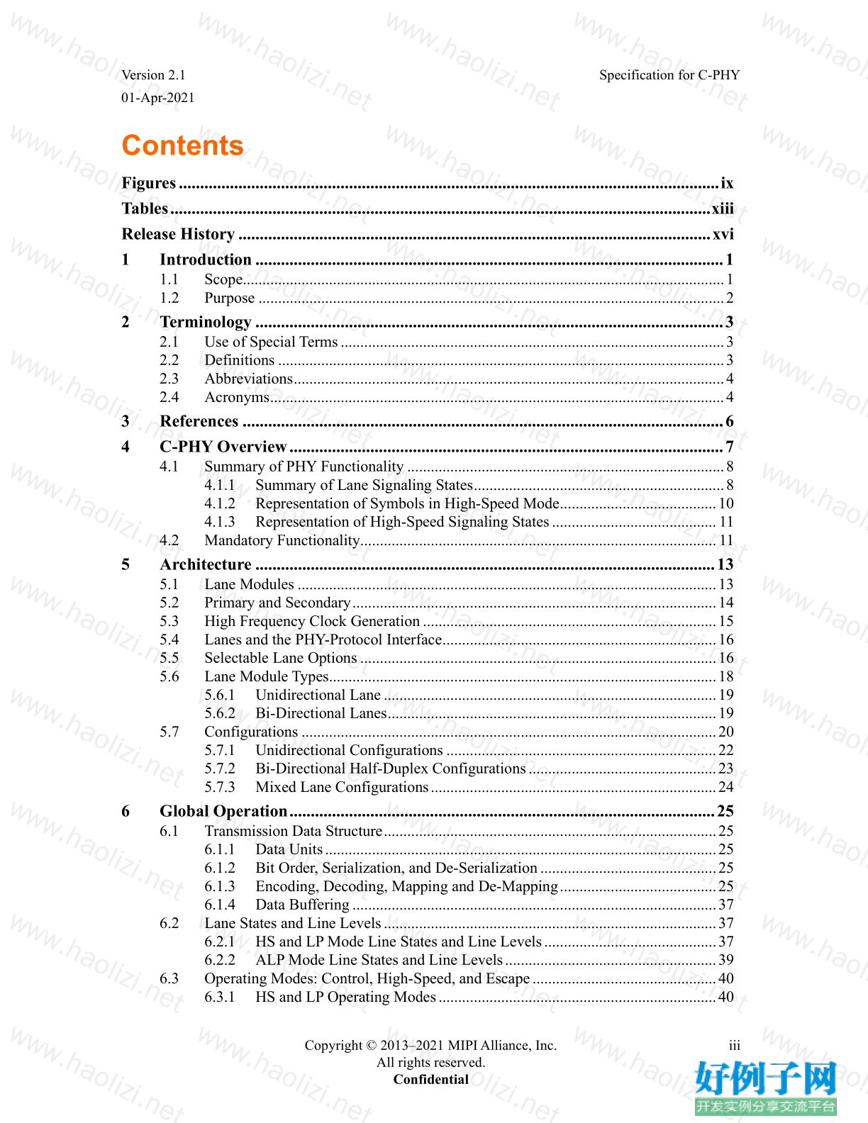
Contents
Figures ............................................................................................................................... ix
Tables ............................................................................................................................... xiii
Release History ............................................................................................................... xvi
1 Introduction .............................................................................................................. 1
1.1 Scope ........................................................................................................................... 1
1.2 Purpose ....................................................................................................................... 2
2 Terminology .............................................................................................................. 3
2.1 Use of Special Terms .................................................................................................. 3
2.2 Definitions .................................................................................................................. 3
2.3 Abbreviations .............................................................................................................. 4
2.4 Acronyms .................................................................................................................... 4
3 References ................................................................................................................. 6
4 C-PHY Overview ...................................................................................................... 7
4.1 Summary of PHY Functionality ................................................................................. 8
4.1.1 Summary of Lane Signaling States ................................................................ 8
4.1.2 Representation of Symbols in High-Speed Mode ........................................ 10
4.1.3 Representation of High-Speed Signaling States .......................................... 11
4.2 Mandatory Functionality ........................................................................................... 11
5 Architecture ............................................................................................................ 13
5.1 Lane Modules ........................................................................................................... 13
5.2 Primary and Secondary ............................................................................................. 14
5.3 High Frequency Clock Generation ........................................................................... 15
5.4 Lanes and the PHY-Protocol Interface ...................................................................... 16
5.5 Selectable Lane Options ........................................................................................... 16
5.6 Lane Module Types ................................................................................................... 18
5.6.1 Unidirectional Lane ..................................................................................... 19
5.6.2 Bi-Directional Lanes .................................................................................... 19
5.7 Configurations .......................................................................................................... 20
5.7.1 Unidirectional Configurations ..................................................................... 22
5.7.2 Bi-Directional Half-Duplex Configurations ................................................ 23
5.7.3 Mixed Lane Configurations ......................................................................... 24
6 Global Operation .................................................................................................... 25
6.1 Transmission Data Structure ..................................................................................... 25
6.1.1 Data Units .................................................................................................... 25
6.1.2 Bit Order, Serialization, and De-Serialization ............................................. 25
6.1.3 Encoding, Decoding, Mapping and De-Mapping ........................................ 25
6.1.4 Data Buffering ............................................................................................. 37
6.2 Lane States and Line Levels ..................................................................................... 37
6.2.1 HS and LP Mode Line States and Line Levels ............................................ 37
6.2.2 ALP Mode Line States and Line Levels ...................................................... 39
6.3 Operating Modes: Control, High-Speed, and Escape ............................................... 40
6.3.1 HS and LP Operating Modes ....................................................................... 40
Specification for C-PHY Version 2.1
01-Apr-2021
iv Copyright © 2013–2021 MIPI Alliance, Inc.
All rights reserved.
Confidential
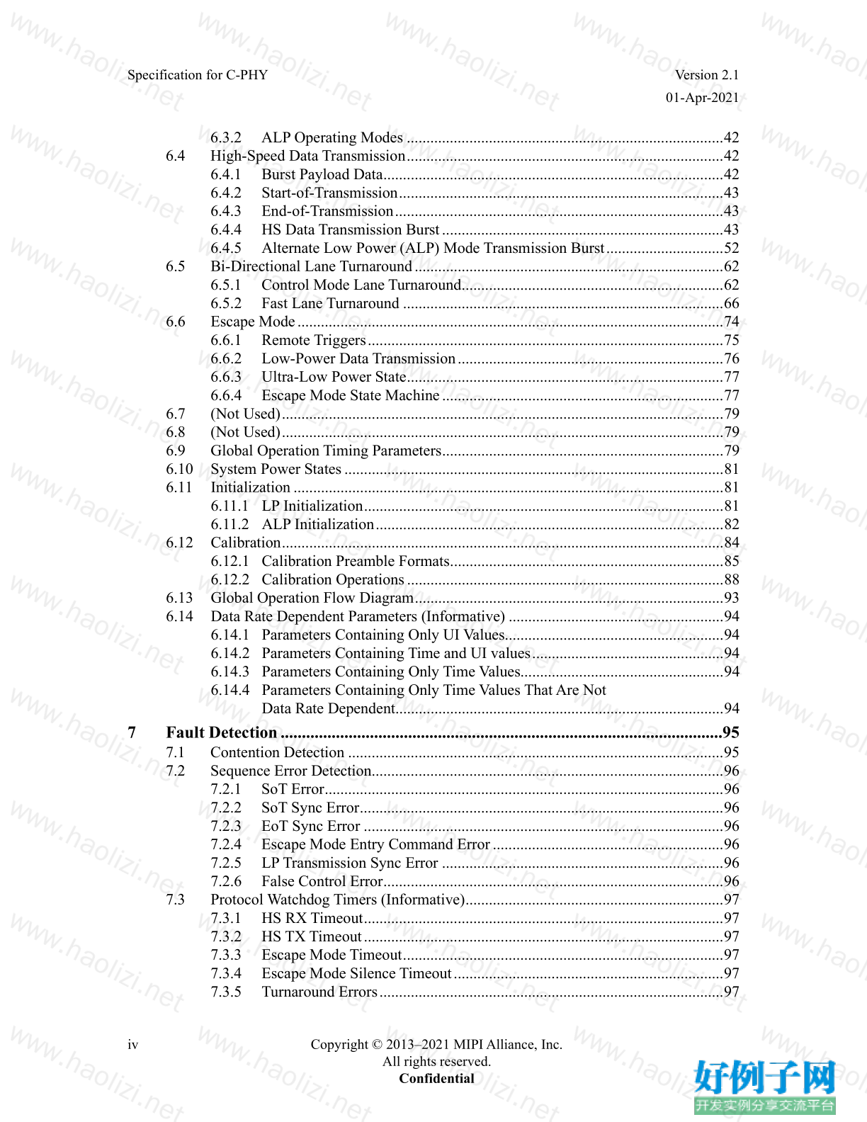
6.3.2 ALP Operating Modes ................................................................................. 42
6.4 High-Speed Data Transmission ................................................................................. 42
6.4.1 Burst Payload Data ....................................................................................... 42
6.4.2 Start-of-Transmission ................................................................................... 43
6.4.3 End-of-Transmission .................................................................................... 43
6.4.4 HS Data Transmission Burst ........................................................................ 43
6.4.5 Alternate Low Power (ALP) Mode Transmission Burst .............................. 52
6.5 Bi-Directional Lane Turnaround ............................................................................... 62
6.5.1 Control Mode Lane Turnaround ................................................................... 62
6.5.2 Fast Lane Turnaround .................................................................................. 66
6.6 Escape Mode ............................................................................................................. 74
6.6.1 Remote Triggers ........................................................................................... 75
6.6.2 Low-Power Data Transmission .................................................................... 76
6.6.3 Ultra-Low Power State ................................................................................. 77
6.6.4 Escape Mode State Machine ........................................................................ 77
6.7 (Not Used) ................................................................................................................. 79
6.8 (Not Used) ................................................................................................................. 79
6.9 Global Operation Timing Parameters ........................................................................ 79
6.10 System Power States ................................................................................................. 81
6.11 Initialization .............................................................................................................. 81
6.11.1 LP Initialization ............................................................................................ 81
6.11.2 ALP Initialization ......................................................................................... 82
6.12 Calibration ................................................................................................................. 84
6.12.1 Calibration Preamble Formats ...................................................................... 85
6.12.2 Calibration Operations ................................................................................. 88
6.13 Global Operation Flow Diagram ............................................................................... 93
6.14 Data Rate Dependent Parameters (Informative) ....................................................... 94
6.14.1 Parameters Containing Only UI Values........................................................ 94
6.14.2 Parameters Containing Time and UI values ................................................. 94
6.14.3 Parameters Containing Only Time Values.................................................... 94
6.14.4 Parameters Containing Only Time Values That Are Not
Data Rate Dependent .................................................................................... 94
7 Fault Detection ........................................................................................................95
7.1 Contention Detection ................................................................................................ 95
7.2 Sequence Error Detection.......................................................................................... 96
7.2.1 SoT Error ...................................................................................................... 96
7.2.2 SoT Sync Error ............................................................................................. 96
7.2.3 EoT Sync Error ............................................................................................ 96
7.2.4 Escape Mode Entry Command Error ........................................................... 96
7.2.5 LP Transmission Sync Error ........................................................................ 96
7.2.6 False Control Error ....................................................................................... 96
7.3 Protocol Watchdog Timers (Informative) .................................................................. 97
7.3.1 HS RX Timeout ............................................................................................ 97
7.3.2 HS TX Timeout ............................................................................................ 97
7.3.3 Escape Mode Timeout .................................................................................. 97
7.3.4 Escape Mode Silence Timeout ..................................................................... 97
7.3.5 Turnaround Errors ........................................................................................ 97
Version 2.1 Specification for C-PHY
01-Apr-2021
Copyright © 2013–2021 MIPI Alliance, Inc. v
All rights reserved.
Confidential
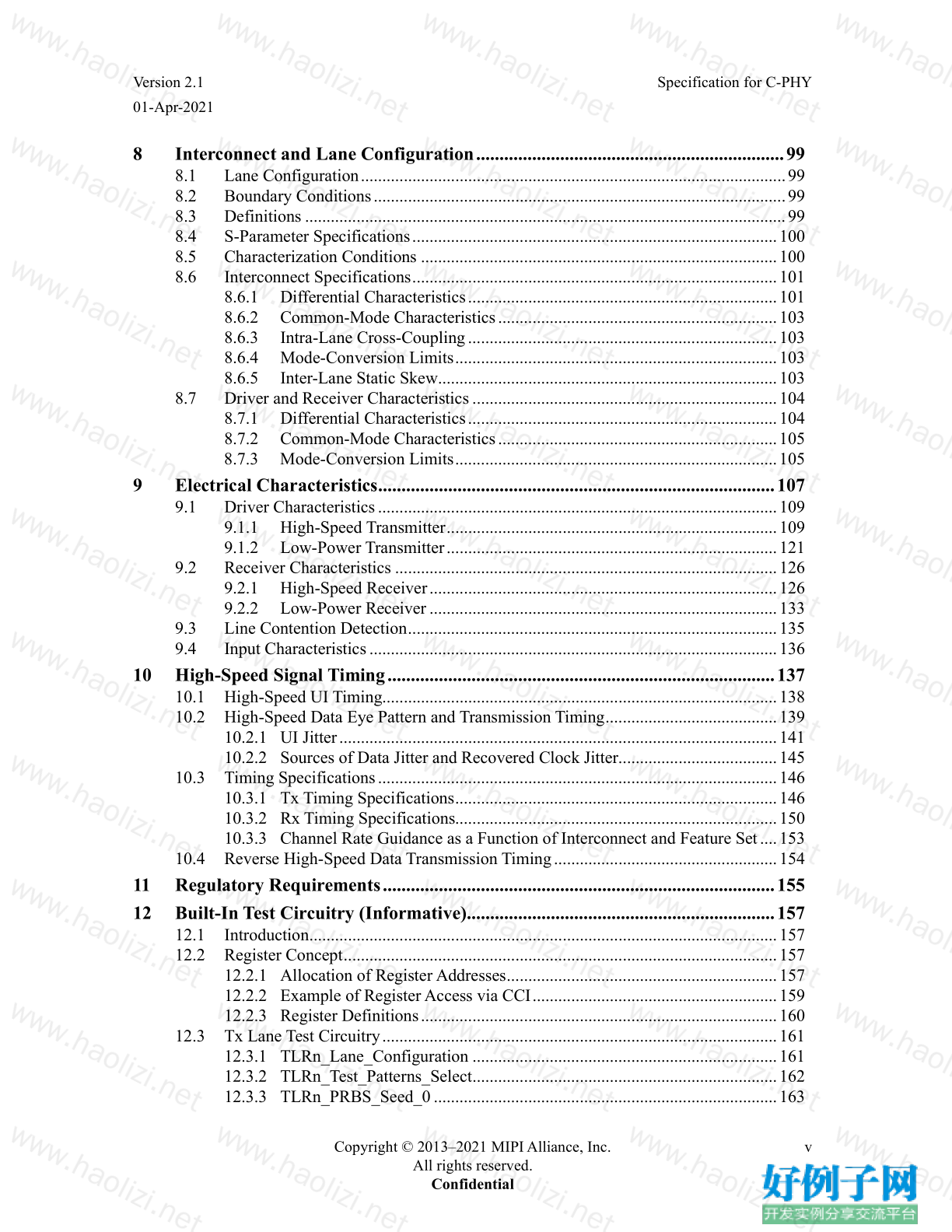
8 Interconnect and Lane Configuration .................................................................. 99
8.1 Lane Configuration ................................................................................................... 99
8.2 Boundary Conditions ................................................................................................ 99
8.3 Definitions ................................................................................................................ 99
8.4 S-Parameter Specifications ..................................................................................... 100
8.5 Characterization Conditions ................................................................................... 100
8.6 Interconnect Specifications ..................................................................................... 101
8.6.1 Differential Characteristics ........................................................................ 101
8.6.2 Common-Mode Characteristics ................................................................. 103
8.6.3 Intra-Lane Cross-Coupling ........................................................................ 103
8.6.4 Mode-Conversion Limits ........................................................................... 103
8.6.5 Inter-Lane Static Skew ............................................................................... 103
8.7 Driver and Receiver Characteristics ....................................................................... 104
8.7.1 Differential Characteristics ........................................................................ 104
8.7.2 Common-Mode Characteristics ................................................................. 105
8.7.3 Mode-Conversion Limits ........................................................................... 105
9 Electrical Characteristics ..................................................................................... 107
9.1 Driver Characteristics ............................................................................................. 109
9.1.1 High-Speed Transmitter ............................................................................. 109
9.1.2 Low-Power Transmitter ............................................................................. 121
9.2 Receiver Characteristics ......................................................................................... 126
9.2.1 High-Speed Receiver ................................................................................. 126
9.2.2 Low-Power Receiver ................................................................................. 133
9.3 Line Contention Detection ...................................................................................... 135
9.4 Input Characteristics ............................................................................................... 136
10 High-Speed Signal Timing ................................................................................... 137
10.1 High-Speed UI Timing............................................................................................ 138
10.2 High-Speed Data Eye Pattern and Transmission Timing ........................................ 139
10.2.1 UI Jitter ...................................................................................................... 141
10.2.2 Sources of Data Jitter and Recovered Clock Jitter ..................................... 145
10.3 Timing Specifications ............................................................................................. 146
10.3.1 Tx Timing Specifications ........................................................................... 146
10.3.2 Rx Timing Specifications........................................................................... 150
10.3.3 Channel Rate Guidance as a Function of Interconnect and Feature Set .... 153
10.4 Reverse High-Speed Data Transmission Timing .................................................... 154
11 Regulatory Requirements .................................................................................... 155
12 Built-In Test Circuitry (Informative).................................................................. 157
12.1 Introduction ............................................................................................................. 157
12.2 Register Concept ..................................................................................................... 157
12.2.1 Allocation of Register Addresses ............................................................... 157
12.2.2 Example of Register Access via CCI ......................................................... 159
12.2.3 Register Definitions ................................................................................... 160
12.3 Tx Lane Test Circuitry ............................................................................................ 161
12.3.1 TLRn_Lane_Configuration ....................................................................... 161
12.3.2 TLRn_Test_Patterns_Select ....................................................................... 162
12.3.3 TLRn_PRBS_Seed_0 ................................................................................ 163
Specification for C-PHY Version 2.1
01-Apr-2021
vi Copyright © 2013–2021 MIPI Alliance, Inc.
All rights reserved.
Confidential
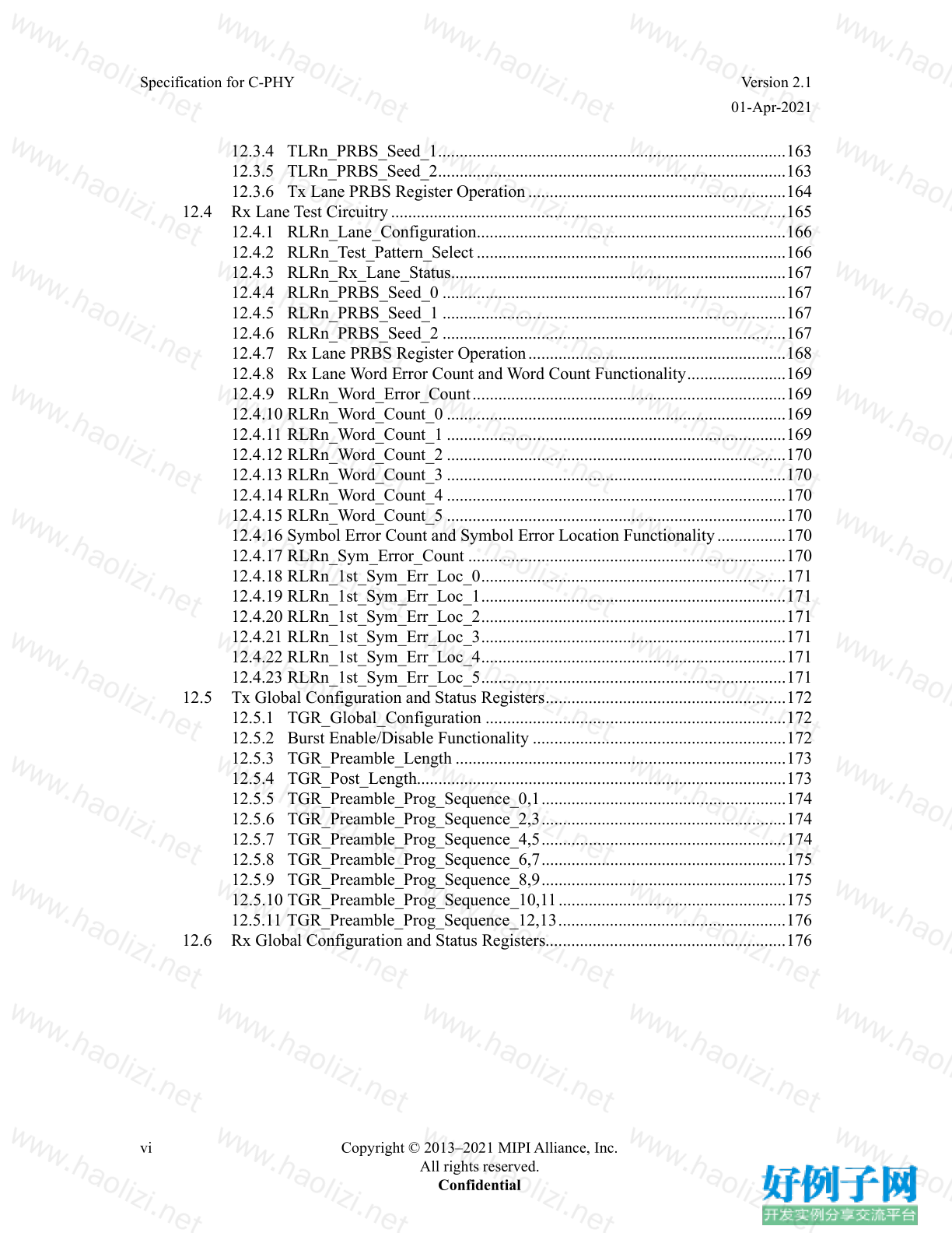
12.3.4 TLRn_PRBS_Seed_1 ................................................................................. 163
12.3.5 TLRn_PRBS_Seed_2 ................................................................................. 163
12.3.6 Tx Lane PRBS Register Operation ............................................................ 164
12.4 Rx Lane Test Circuitry ............................................................................................ 165
12.4.1 RLRn_Lane_Configuration ........................................................................ 166
12.4.2 RLRn_Test_Pattern_Select ........................................................................ 166
12.4.3 RLRn_Rx_Lane_Status .............................................................................. 167
12.4.4 RLRn_PRBS_Seed_0 ................................................................................ 167
12.4.5 RLRn_PRBS_Seed_1 ................................................................................ 167
12.4.6 RLRn_PRBS_Seed_2 ................................................................................ 167
12.4.7 Rx Lane PRBS Register Operation ............................................................ 168
12.4.8 Rx Lane Word Error Count and Word Count Functionality ....................... 169
12.4.9 RLRn_Word_Error_Count ......................................................................... 169
12.4.10 RLRn_Word_Count_0 ............................................................................... 169
12.4.11 RLRn_Word_Count_1 ............................................................................... 169
12.4.12 RLRn_Word_Count_2 ............................................................................... 170
12.4.13 RLRn_Word_Count_3 ............................................................................... 170
12.4.14 RLRn_Word_Count_4 ............................................................................... 170
12.4.15 RLRn_Word_Count_5 ............................................................................... 170
12.4.16 Symbol Error Count and Symbol Error Location Functionality ................ 170
12.4.17 RLRn_Sym_Error_Count .......................................................................... 170
12.4.18 RLRn_1st_Sym_Err_Loc_0 ....................................................................... 171
12.4.19 RLRn_1st_Sym_Err_Loc_1 ....................................................................... 171
12.4.20 RLRn_1st_Sym_Err_Loc_2 ....................................................................... 171
12.4.21 RLRn_1st_Sym_Err_Loc_3 ....................................................................... 171
12.4.22 RLRn_1st_Sym_Err_Loc_4 ....................................................................... 171
12.4.23 RLRn_1st_Sym_Err_Loc_5 ....................................................................... 171
12.5 Tx Global Configuration and Status Registers ........................................................ 172
12.5.1 TGR_Global_Configuration ...................................................................... 172
12.5.2 Burst Enable/Disable Functionality ........................................................... 172
12.5.3 TGR_Preamble_Length ............................................................................. 173
12.5.4 TGR_Post_Length...................................................................................... 173
12.5.5 TGR_Preamble_Prog_Sequence_0,1 ......................................................... 174
12.5.6 TGR_Preamble_Prog_Sequence_2,3 ......................................................... 174
12.5.7 TGR_Preamble_Prog_Sequence_4,5 ......................................................... 174
12.5.8 TGR_Preamble_Prog_Sequence_6,7 ......................................................... 175
12.5.9 TGR_Preamble_Prog_Sequence_8,9 ......................................................... 175
12.5.10 TGR_Preamble_Prog_Sequence_10,11 ..................................................... 175
12.5.11 TGR_Preamble_Prog_Sequence_12,13 ..................................................... 176
12.6 Rx Global Configuration and Status Registers........................................................ 176
Version 2.1 Specification for C-PHY
01-Apr-2021
Copyright © 2013–2021 MIPI Alliance, Inc. vii
All rights reserved.
Confidential
Annex A Logical PHY-Protocol Interface Description (Informative) ................... 177
A.1 Signal Description................................................................................................... 177
A.2 PHY Enable Processes ............................................................................................ 204
A.3 (Not Used) .............................................................................................................. 205
A.4 High-Speed Transmission from the Primary or Secondary .................................... 205
A.4.1 Transmission of a Data Burst with a Calibration Preamble from
the Primary or Secondary .......................................................................... 207
A.5 High-Speed Reception at the Secondary or Primary .............................................. 208
A.5.1 Reception of a Data Burst with a Calibration Preamble at the
Primary or Secondary ................................................................................ 211
A.6 High-Speed Transmission from the Secondary ....................................................... 212
A.7 High-Speed Reception at the Primary..................................................................... 212
A.8 Low-Power Data Transmission ............................................................................... 212
A.9 Low-Power Data Reception .................................................................................... 213
A.10 Bi-directional Lane Turn-Around ........................................................................... 214
A.10.1 Control Mode Lane Turnaround ................................................................ 214
A.10.2 Fast Lane Turnaround ................................................................................ 215
A.11 Trigger Command ................................................................................................... 217
A.12 ULPS Transition ..................................................................................................... 219
A.13 (Not Used) .............................................................................................................. 219
A.14 (Not Used) .............................................................................................................. 219
A.15 High Speed Transmit Data Transfer Enable............................................................ 220
A.16 (Not Used) .............................................................................................................. 220
A.17 Line Sequence Errors Reported By ErrControl ...................................................... 221
A.18 Optical Link Support .............................................................................................. 223
A.18.1 System Setup ............................................................................................. 223
A.18.2 Serializer and De-Serializer Block Diagrams ............................................ 224
A.18.3 Timing Constraints..................................................................................... 225
A.18.4 System Constraints .................................................................................... 226
A.19 Dynamic LP and ALP Operation ............................................................................ 227
A.19.1 Description of Operation ........................................................................... 228
A.19.2 LP and ALP - PPI Controls ........................................................................ 231
Annex B Interconnect Design Guidelines (Informative) ........................................ 233
B.1 Practical Distances .................................................................................................. 233
B.2 RF Frequency Bands: Interference ......................................................................... 233
B.2.1 Specific Recommendations Regarding EMI and EMC ............................. 234
B.3 Transmission Line Design ...................................................................................... 238
B.4 Reference Layer ...................................................................................................... 238
B.5 Printed-Circuit Board .............................................................................................. 238
B.6 Flex Circuits ............................................................................................................ 238
B.7 Series Resistance..................................................................................................... 238
B.8 Connectors .............................................................................................................. 238
B.9 Verification Bench Example ................................................................................... 239
Specification for C-PHY Version 2.1
01-Apr-2021
viii Copyright © 2013–2021 MIPI Alliance, Inc.
All rights reserved.
Confidential
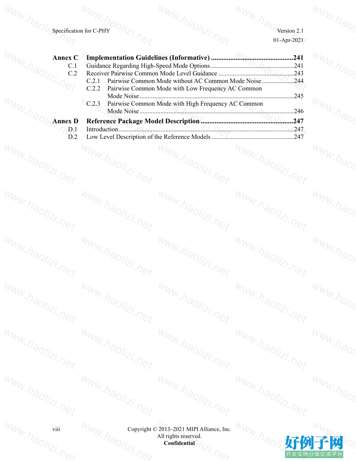
Annex C Implementation Guidelines (Informative) ...............................................241
C.1 Guidance Regarding High-Speed Mode Options .................................................... 241
C.2 Receiver Pairwise Common Mode Level Guidance ............................................... 243
C.2.1 Pairwise Common Mode without AC Common Mode Noise .................... 244
C.2.2 Pairwise Common Mode with Low Frequency AC Common
Mode Noise ................................................................................................ 245
C.2.3 Pairwise Common Mode with High Frequency AC Common
Mode Noise ................................................................................................ 246
Annex D Reference Package Model Description .....................................................247
D.1 Introduction ............................................................................................................. 247
D.2 Low Level Description of the Reference Models ................................................... 247
Version 2.1 Specification for C-PHY
01-Apr-2021
Copyright © 2013–2021 MIPI Alliance, Inc. ix
All rights reserved.
Confidential
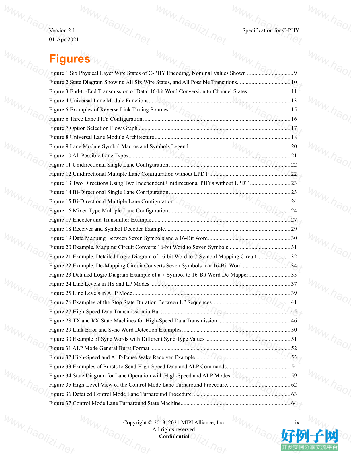
Figures
Figure 1 Six Physical Layer Wire States of C-PHY Encoding, Nominal Values Shown ................................ 9
Figure 2 State Diagram Showing All Six Wire States, and All Possible Transitions ..................................... 10
Figure 3 End-to-End Transmission of Data, 16-bit Word Conversion to Channel States .............................. 11
Figure 4 Universal Lane Module Functions .................................................................................................. 13
Figure 5 Examples of Reverse Link Timing Sources .................................................................................... 15
Figure 6 Three Lane PHY Configuration ...................................................................................................... 16
Figure 7 Option Selection Flow Graph ......................................................................................................... 17
Figure 8 Universal Lane Module Architecture .............................................................................................. 18
Figure 9 Lane Module Symbol Macros and Symbols Legend ...................................................................... 20
Figure 10 All Possible Lane Types ................................................................................................................ 21
Figure 11 Unidirectional Single Lane Configuration .................................................................................... 22
Figure 12 Unidirectional Multiple Lane Configuration without LPDT ........................................................ 22
Figure 13 Two Directions Using Two Independent Unidirectional PHYs without LPDT ............................ 23
Figure 14 Bi-Directional Single Lane Configuration .................................................................................... 23
Figure 15 Bi-Directional Multiple Lane Configuration ................................................................................ 24
Figure 16 Mixed Type Multiple Lane Configuration .................................................................................... 24
Figure 17 Encoder and Transmitter Example ................................................................................................ 27
Figure 18 Receiver and Symbol Decoder Example ....................................................................................... 29
Figure 19 Data Mapping Between Seven Symbols and a 16-Bit Word ......................................................... 30
Figure 20 Example, Mapping Circuit Converts 16-bit Word to Seven Symbols ........................................... 31
Figure 21 Example, Detailed Logic Diagram of 16-bit Word to 7-Symbol Mapping Circuit ....................... 32
Figure 22 Example, De-Mapping Circuit Converts Seven Symbols to a 16-Bit Word ................................. 34
Figure 23 Detailed Logic Diagram Example of a 7-Symbol to 16-Bit Word De-Mapper ............................. 35
Figure 24 Line Levels in HS and LP Modes ................................................................................................. 37
Figure 25 Line Levels in ALP Mode ............................................................................................................. 39
Figure 26 Examples of the Stop State Duration Between LP Sequences ...................................................... 41
Figure 27 High-Speed Data Transmission in Burst ....................................................................................... 45
Figure 28 TX and RX State Machines for High-Speed Data Transmission .................................................. 46
Figure 29 Link Error and Sync Word Detection Examples ........................................................................... 50
Figure 30 Example of Sync Words with Different Sync Type Values ........................................................... 51
Figure 31 ALP Mode General Burst Format ................................................................................................. 52
Figure 32 High-Speed and ALP-Pause Wake Receiver Example .................................................................. 53
Figure 33 Examples of Bursts to Send High-Speed Data and ALP Commands ............................................ 54
Figure 34 State Diagram for Lane Operation with High-Speed and ALP Modes ......................................... 59
Figure 35 High-Level View of the Control Mode Lane Turnaround Procedure ............................................ 62
Figure 36 Detailed Control Mode Lane Turnaround Procedure .................................................................... 63
Figure 37 Control Mode Lane Turnaround State Machine ............................................................................ 64
Specification for C-PHY Version 2.1
01-Apr-2021
x Copyright © 2013–2021 MIPI Alliance, Inc.
All rights reserved.
Confidential
Figure 38 High-Level View of the Fast Lane Turnaround Procedure with ALP Mode ................................. 66
Figure 39 High-Level View, Comparing Lane Turnaround Procedures ........................................................ 66
Figure 40 Fast Lane Turnaround Procedure .................................................................................................. 68
Figure 41 Fast Lane Turnaround State Machine ............................................................................................ 71
Figure 42 Trigger-Reset Command in Escape Mode ..................................................................................... 74
Figure 43 Two Data Byte Low-Power Data Transmission Example ............................................................. 76
Figure 44 Escape Mode State Machine ......................................................................................................... 77
Figure 45 Examples of the Initialization Period after Power-Up ................................................................... 83
Figure 46 Normal Preambles Vs. Calibration Preambles .............................................................................. 84
Figure 47 High-Speed Data Transmission in Rx-Calibration ........................................................................ 85
Figure 48 PRBS9 Sequence Generator for the Alternate Sequence ............................................................... 86
Figure 49 Lane Module State Diagram ......................................................................................................... 93
Figure 50 Point-to-Point Interconnect ........................................................................................................... 99
Figure 51 Set-up for S-Parameter Characterization of RX, TX, and TLIS .................................................. 100
Figure 52 Template for Differential Insertion Losses .................................................................................. 101
Figure 53 Template for Differential Insertion Losses, C-PHY Legacy Channel ......................................... 102
Figure 54 Differential Reflection Template for Lane Module Receivers .................................................... 104
Figure 55 Differential Reflection Template for Lane Module Transmitters ................................................ 104
Figure 56 Template for RX Common-Mode Return Loss ........................................................................... 105
Figure 57 Electrical Functions of a Fully Featured C-PHY Transceiver ..................................................... 107
Figure 58 C-PHY Signaling Levels ............................................................................................................. 108
Figure 59 Example High-Speed Transmitter ............................................................................................... 109
Figure 60 Ideal Single-Ended and Resulting Differential High-Speed Signals ........................................... 111
Figure 61 Possible V CPTX and ΔV OD Distortions of the Single-Ended HS Signals ...................................... 112
Figure 62 Example Circuit for V OD and V CPTX Measurements .................................................................... 112
Figure 63 Example of High, Mid, and Low Sublevels for Advanced Tx Equalization ............................... 117
Figure 64 Example Switched Leg Implementation ..................................................................................... 117
Figure 65 Example Waveforms With and Without Advanced Tx Equalization ........................................... 118
Figure 66 Example LP Transmitter .............................................................................................................. 121
Figure 67 V-I Characteristic for LP Transmitter Driving Logic High ......................................................... 121
Figure 68 V-I Characteristic for LP Transmitter Driving Logic Low .......................................................... 122
Figure 69 LP Transmitter V-I Characteristic Measurement Setup ............................................................... 122
Figure 70 Slew Rate vs. C LOAD (Falling Edge) ............................................................................................ 125
Figure 71 Slew Rate vs. C LOAD (Rising Edge) ............................................................................................. 125
Figure 72 HS Receiver Implementation Example ....................................................................................... 126
Figure 73 Example of CTLE Frequency Response ..................................................................................... 130
Figure 74 Input Glitch Rejection of Low-Power Receivers ........................................................................ 133
Figure 75 Signaling and Contention Voltage Levels ................................................................................... 135
Figure 76 Pin Leakage Measurement Example Circuit ............................................................................... 136
Version 2.1 Specification for C-PHY
01-Apr-2021
Copyright © 2013–2021 MIPI Alliance, Inc. xi
All rights reserved.
Confidential
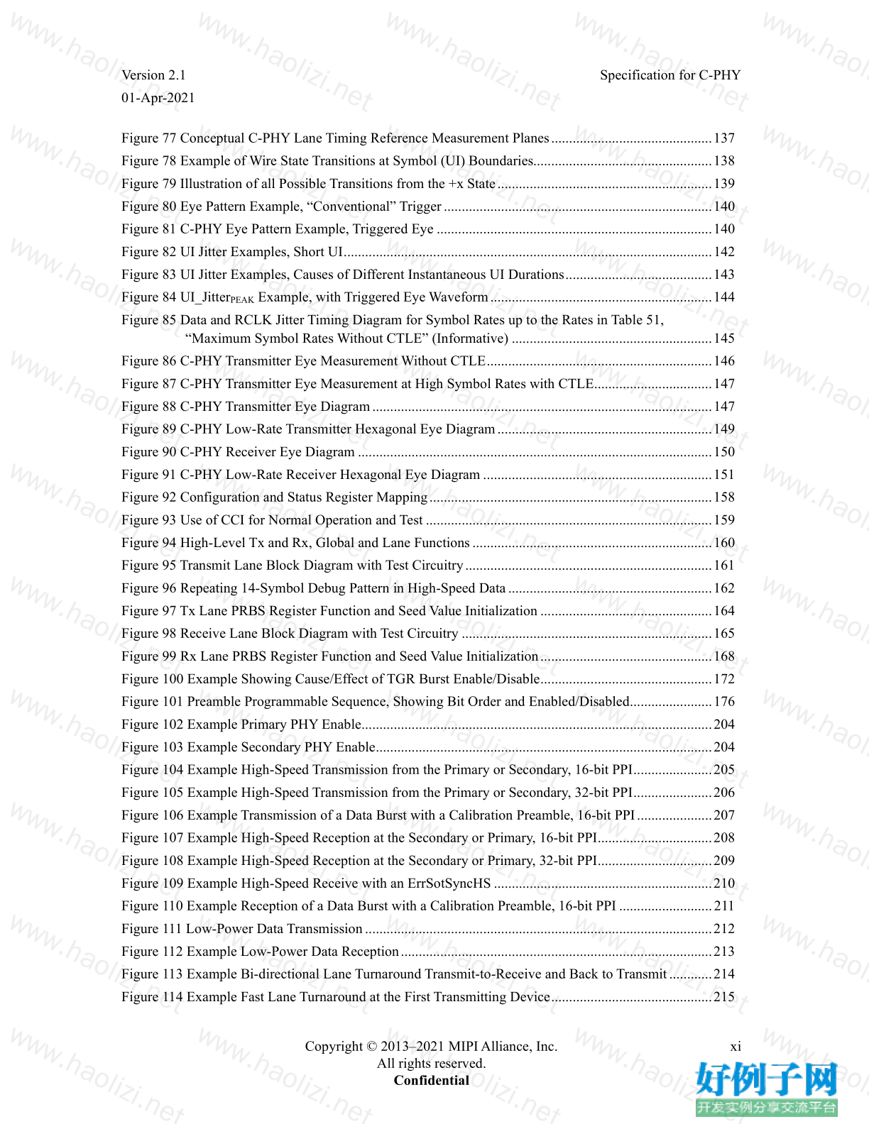
Figure 77 Conceptual C-PHY Lane Timing Reference Measurement Planes ............................................. 137
Figure 78 Example of Wire State Transitions at Symbol (UI) Boundaries.................................................. 138
Figure 79 Illustration of all Possible Transitions from the x State ............................................................ 139
Figure 80 Eye Pattern Example, “Conventional” Trigger ........................................................................... 140
Figure 81 C-PHY Eye Pattern Example, Triggered Eye ............................................................................. 140
Figure 82 UI Jitter Examples, Short UI ....................................................................................................... 142
Figure 83 UI Jitter Examples, Causes of Different Instantaneous UI Durations ......................................... 143
Figure 84 UI_Jitter PEAK Example, with Triggered Eye Waveform .............................................................. 144
Figure 85 Data and RCLK Jitter Timing Diagram for Symbol Rates up to the Rates in Table 51,
“Maximum Symbol Rates Without CTLE” (Informative) ........................................................ 145
Figure 86 C-PHY Transmitter Eye Measurement Without CTLE ............................................................... 146
Figure 87 C-PHY Transmitter Eye Measurement at High Symbol Rates with CTLE ................................. 147
Figure 88 C-PHY Transmitter Eye Diagram ............................................................................................... 147
Figure 89 C-PHY Low-Rate Transmitter Hexagonal Eye Diagram ............................................................ 149
Figure 90 C-PHY Receiver Eye Diagram ................................................................................................... 150
Figure 91 C-PHY Low-Rate Receiver Hexagonal Eye Diagram ................................................................ 151
Figure 92 Configuration and Status Register Mapping ............................................................................... 158
Figure 93 Use of CCI for Normal Operation and Test ................................................................................ 159
Figure 94 High-Level Tx and Rx, Global and Lane Functions ................................................................... 160
Figure 95 Transmit Lane Block Diagram with Test Circuitry ..................................................................... 161
Figure 96 Repeating 14-Symbol Debug Pattern in High-Speed Data ......................................................... 162
Figure 97 Tx Lane PRBS Register Function and Seed Value Initialization ................................................ 164
Figure 98 Receive Lane Block Diagram with Test Circuitry ...................................................................... 165
Figure 99 Rx Lane PRBS Register Function and Seed Value Initialization ................................................ 168
Figure 100 Example Showing Cause/Effect of TGR Burst Enable/Disable ................................................ 172
Figure 101 Preamble Programmable Sequence, Showing Bit Order and Enabled/Disabled ....................... 176
Figure 102 Example Primary PHY Enable .................................................................................................. 204
Figure 103 Example Secondary PHY Enable .............................................................................................. 204
Figure 104 Example High-Speed Transmission from the Primary or Secondary, 16-bit PPI ...................... 205
Figure 105 Example High-Speed Transmission from the Primary or Secondary, 32-bit PPI ...................... 206
Figure 106 Example Transmission of a Data Burst with a Calibration Preamble, 16-bit PPI ..................... 207
Figure 107 Example High-Speed Reception at the Secondary or Primary, 16-bit PPI ................................ 208
Figure 108 Example High-Speed Reception at the Secondary or Primary, 32-bit PPI ................................ 209
Figure 109 Example High-Speed Receive with an ErrSotSyncHS ............................................................. 210
Figure 110 Example Reception of a Data Burst with a Calibration Preamble, 16-bit PPI .......................... 211
Figure 111 Low-Power Data Transmission ................................................................................................. 212
Figure 112 Example Low-Power Data Reception ....................................................................................... 213
Figure 113 Example Bi-directional Lane Turnaround Transmit-to-Receive and Back to Transmit ............ 214
Figure 114 Example Fast Lane Turnaround at the First Transmitting Device ............................................. 215
Specification for C-PHY Version 2.1
01-Apr-2021
xii Copyright © 2013–2021 MIPI Alliance, Inc.
All rights reserved.
Confidential
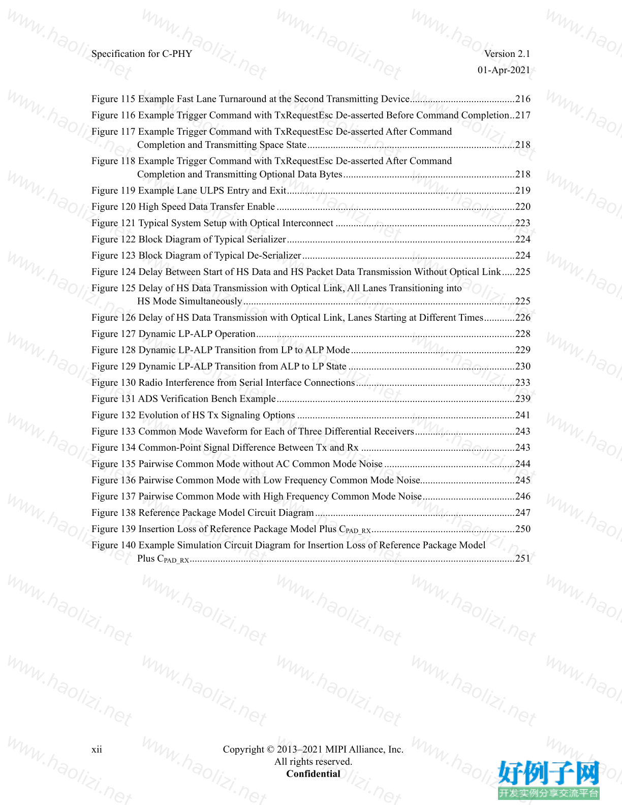
Figure 115 Example Fast Lane Turnaround at the Second Transmitting Device ......................................... 216
Figure 116 Example Trigger Command with TxRequestEsc De-asserted Before Command Completion .. 217
Figure 117 Example Trigger Command with TxRequestEsc De-asserted After Command
Completion and Transmitting Space State ................................................................................. 218
Figure 118 Example Trigger Command with TxRequestEsc De-asserted After Command
Completion and Transmitting Optional Data Bytes ................................................................... 218
Figure 119 Example Lane ULPS Entry and Exit ......................................................................................... 219
Figure 120 High Speed Data Transfer Enable ............................................................................................. 220
Figure 121 Typical System Setup with Optical Interconnect ...................................................................... 223
Figure 122 Block Diagram of Typical Serializer ......................................................................................... 224
Figure 123 Block Diagram of Typical De-Serializer ................................................................................... 224
Figure 124 Delay Between Start of HS Data and HS Packet Data Transmission Without Optical Link ..... 225
Figure 125 Delay of HS Data Transmission with Optical Link, All Lanes Transitioning into
HS Mode Simultaneously .......................................................................................................... 225
Figure 126 Delay of HS Data Transmission with Optical Link, Lanes Starting at Different Times ............ 226
Figure 127 Dynamic LP-ALP Operation ..................................................................................................... 228
Figure 128 Dynamic LP-ALP Transition from LP to ALP Mode ................................................................ 229
Figure 129 Dynamic LP-ALP Transition from ALP to LP State ................................................................. 230
Figure 130 Radio Interference from Serial Interface Connections .............................................................. 233
Figure 131 ADS Verification Bench Example ............................................................................................. 239
Figure 132 Evolution of HS Tx Signaling Options ..................................................................................... 241
Figure 133 Common Mode Waveform for Each of Three Differential Receivers ....................................... 243
Figure 134 Common-Point Signal Difference Between Tx and Rx ............................................................ 243
Figure 135 Pairwise Common Mode without AC Common Mode Noise ................................................... 244
Figure 136 Pairwise Common Mode with Low Frequency Common Mode Noise..................................... 245
Figure 137 Pairwise Common Mode with High Frequency Common Mode Noise .................................... 246
Figure 138 Reference Package Model Circuit Diagram .............................................................................. 247
Figure 139 Insertion Loss of Reference Package Model Plus C PAD_RX ........................................................ 250
Figure 140 Example Simulation Circuit Diagram for Insertion Loss of Reference Package Model
Plus C PAD_RX ............................................................................................................................... 251
Version 2.1 Specification for C-PHY
01-Apr-2021
Copyright © 2013–2021 MIPI Alliance, Inc. xiii
All rights reserved.
Confidential
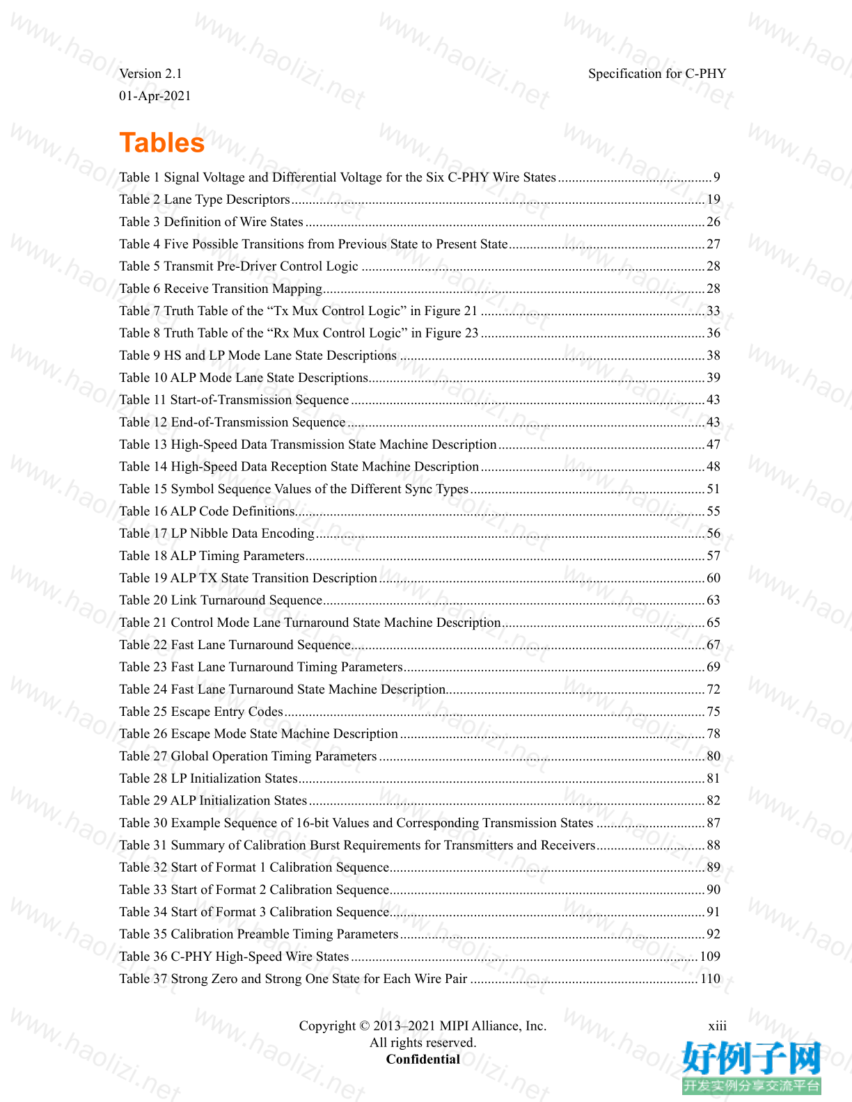
Tables
Table 1 Signal Voltage and Differential Voltage for the Six C-PHY Wire States ............................................ 9
Table 2 Lane Type Descriptors ...................................................................................................................... 19
Table 3 Definition of Wire States .................................................................................................................. 26
Table 4 Five Possible Transitions from Previous State to Present State ........................................................ 27
Table 5 Transmit Pre-Driver Control Logic .................................................................................................. 28
Table 6 Receive Transition Mapping ............................................................................................................. 28
Table 7 Truth Table of the “Tx Mux Control Logic” in Figure 21 ................................................................ 33
Table 8 Truth Table of the “Rx Mux Control Logic” in Figure 23 ................................................................ 36
Table 9 HS and LP Mode Lane State Descriptions ....................................................................................... 38
Table 10 ALP Mode Lane State Descriptions ................................................................................................ 39
Table 11 Start-of-Transmission Sequence ..................................................................................................... 43
Table 12 End-of-Transmission Sequence ...................................................................................................... 43
Table 13 High-Speed Data Transmission State Machine Description ........................................................... 47
Table 14 High-Speed Data Reception State Machine Description ................................................................ 48
Table 15 Symbol Sequence Values of the Different Sync Types ................................................................... 51
Table 16 ALP Code Definitions..................................................................................................................... 55
Table 17 LP Nibble Data Encoding ............................................................................................................... 56
Table 18 ALP Timing Parameters .................................................................................................................. 57
Table 19 ALP TX State Transition Description ............................................................................................. 60
Table 20 Link Turnaround Sequence ............................................................................................................. 63
Table 21 Control Mode Lane Turnaround State Machine Description .......................................................... 65
Table 22 Fast Lane Turnaround Sequence ..................................................................................................... 67
Table 23 Fast Lane Turnaround Timing Parameters ...................................................................................... 69
Table 24 Fast Lane Turnaround State Machine Description.......................................................................... 72
Table 25 Escape Entry Codes ........................................................................................................................ 75
Table 26 Escape Mode State Machine Description ....................................................................................... 78
Table 27 Global Operation Timing Parameters ............................................................................................. 80
Table 28 LP Initialization States .................................................................................................................... 81
Table 29 ALP Initialization States ................................................................................................................. 82
Table 30 Example Sequence of 16-bit Values and Corresponding Transmission States ............................... 87
Table 31 Summary of Calibration Burst Requirements for Transmitters and Receivers ............................... 88
Table 32 Start of Format 1 Calibration Sequence .......................................................................................... 89
Table 33 Start of Format 2 Calibration Sequence .......................................................................................... 90
Table 34 Start of Format 3 Calibration Sequence .......................................................................................... 91
Table 35 Calibration Preamble Timing Parameters ....................................................................................... 92
Table 36 C-PHY High-Speed Wire States ................................................................................................... 109
Table 37 Strong Zero and Strong One State for Each Wire Pair ................................................................. 110
Specification for C-PHY Version 2.1
01-Apr-2021
xiv Copyright © 2013–2021 MIPI Alliance, Inc.
All rights reserved.
Confidential
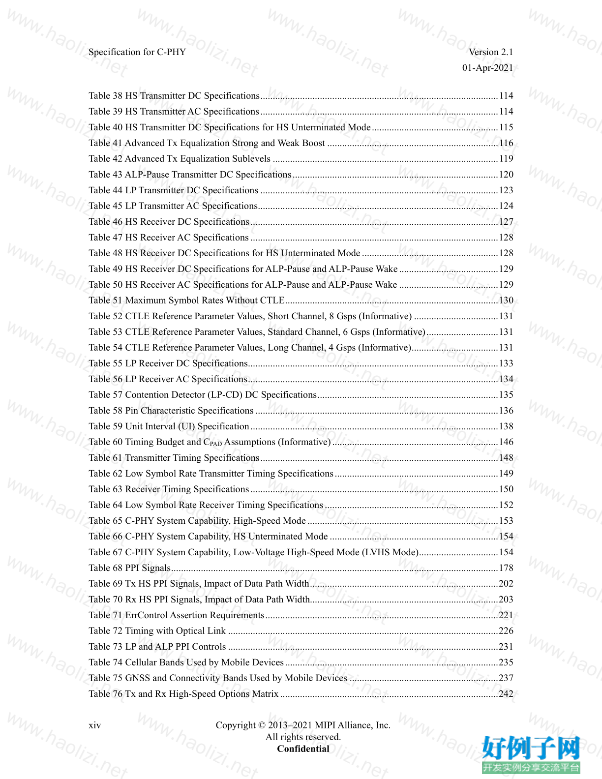
Table 38 HS Transmitter DC Specifications ................................................................................................ 114
Table 39 HS Transmitter AC Specifications ................................................................................................ 114
Table 40 HS Transmitter DC Specifications for HS Unterminated Mode ................................................... 115
Table 41 Advanced Tx Equalization Strong and Weak Boost ..................................................................... 116
Table 42 Advanced Tx Equalization Sublevels ........................................................................................... 119
Table 43 ALP-Pause Transmitter DC Specifications ................................................................................... 120
Table 44 LP Transmitter DC Specifications ................................................................................................ 123
Table 45 LP Transmitter AC Specifications ................................................................................................. 124
Table 46 HS Receiver DC Specifications .................................................................................................... 127
Table 47 HS Receiver AC Specifications .................................................................................................... 128
Table 48 HS Receiver DC Specifications for HS Unterminated Mode ....................................................... 128
Table 49 HS Receiver DC Specifications for ALP-Pause and ALP-Pause Wake ........................................ 129
Table 50 HS Receiver AC Specifications for ALP-Pause and ALP-Pause Wake ........................................ 129
Table 51 Maximum Symbol Rates Without CTLE ...................................................................................... 130
Table 52 CTLE Reference Parameter Values, Short Channel, 8 Gsps (Informative) .................................. 131
Table 53 CTLE Reference Parameter Values, Standard Channel, 6 Gsps (Informative) ............................. 131
Table 54 CTLE Reference Parameter Values, Long Channel, 4 Gsps (Informative) ................................... 131
Table 55 LP Receiver DC Specifications ..................................................................................................... 133
Table 56 LP Receiver AC Specifications ..................................................................................................... 134
Table 57 Contention Detector (LP-CD) DC Specifications ......................................................................... 135
Table 58 Pin Characteristic Specifications .................................................................................................. 136
Table 59 Unit Interval (UI) Specification .................................................................................................... 138
Table 60 Timing Budget and C PAD Assumptions (Informative) ................................................................... 146
Table 61 Transmitter Timing Specifications ................................................................................................ 148
Table 62 Low Symbol Rate Transmitter Timing Specifications .................................................................. 149
Table 63 Receiver Timing Specifications .................................................................................................... 150
Table 64 Low Symbol Rate Receiver Timing Specifications ...................................................................... 152
Table 65 C-PHY System Capability, High-Speed Mode ............................................................................. 153
Table 66 C-PHY System Capability, HS Unterminated Mode .................................................................... 154
Table 67 C-PHY System Capability, Low-Voltage High-Speed Mode (LVHS Mode) ................................ 154
Table 68 PPI Signals .................................................................................................................................... 178
Table 69 Tx HS PPI Signals, Impact of Data Path Width ............................................................................ 202
Table 70 Rx HS PPI Signals, Impact of Data Path Width............................................................................ 203
Table 71 ErrControl Assertion Requirements .............................................................................................. 221
Table 72 Timing with Optical Link ............................................................................................................. 226
Table 73 LP and ALP PPI Controls ............................................................................................................. 231
Table 74 Cellular Bands Used by Mobile Devices ...................................................................................... 235
Table 75 GNSS and Connectivity Bands Used by Mobile Devices ............................................................ 237
Table 76 Tx and Rx High-Speed Options Matrix ........................................................................................ 242
Version 2.1 Specification for C-PHY
01-Apr-2021
Copyright © 2013–2021 MIPI Alliance, Inc. xv
All rights reserved.
Confidential
Table 77 Package Model Substrate Properties, MLSUBSTRATE2 ............................................................ 248
Table 78 Coupled Line Properties, ML3CTL_C ......................................................................................... 248
Table 79 Via Pad Properties, MLVIAPAD .................................................................................................. 249
Table 80 Via Hole Properties, MLVIAHOLE ............................................................................................. 249
Table 81 Via Clearance Properties, MLCLE ............................................................................................... 249
小贴士
感谢您为本站写下的评论,您的评论对其它用户来说具有重要的参考价值,所以请认真填写。
- 类似“顶”、“沙发”之类没有营养的文字,对勤劳贡献的楼主来说是令人沮丧的反馈信息。
- 相信您也不想看到一排文字/表情墙,所以请不要反馈意义不大的重复字符,也请尽量不要纯表情的回复。
- 提问之前请再仔细看一遍楼主的说明,或许是您遗漏了。
- 请勿到处挖坑绊人、招贴广告。既占空间让人厌烦,又没人会搭理,于人于己都无利。
关于好例子网
本站旨在为广大IT学习爱好者提供一个非营利性互相学习交流分享平台。本站所有资源都可以被免费获取学习研究。本站资源来自网友分享,对搜索内容的合法性不具有预见性、识别性、控制性,仅供学习研究,请务必在下载后24小时内给予删除,不得用于其他任何用途,否则后果自负。基于互联网的特殊性,平台无法对用户传输的作品、信息、内容的权属或合法性、安全性、合规性、真实性、科学性、完整权、有效性等进行实质审查;无论平台是否已进行审查,用户均应自行承担因其传输的作品、信息、内容而可能或已经产生的侵权或权属纠纷等法律责任。本站所有资源不代表本站的观点或立场,基于网友分享,根据中国法律《信息网络传播权保护条例》第二十二与二十三条之规定,若资源存在侵权或相关问题请联系本站客服人员,点此联系我们。关于更多版权及免责申明参见 版权及免责申明


网友评论
我要评论