实例介绍
【实例截图】
【核心代码】
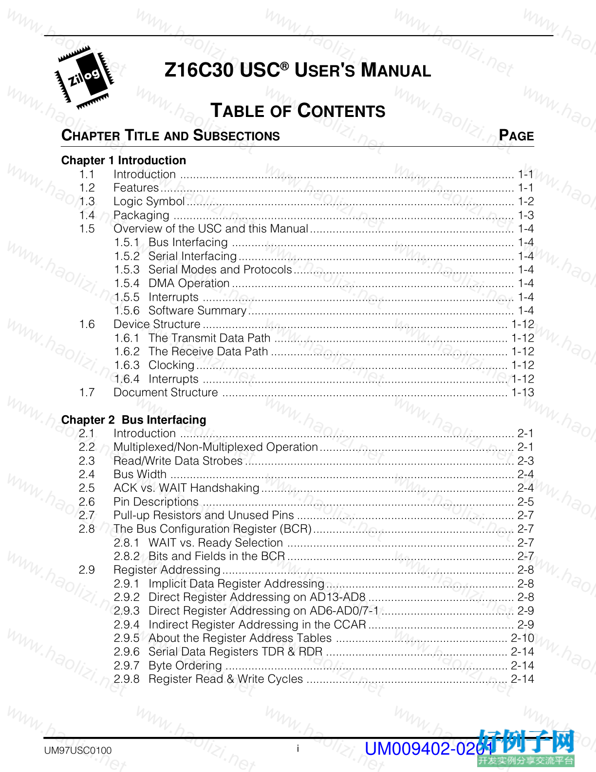
Chapter 1 Introduction
1.1 Introduction ....................................................................................................... 1-1
1.2 Features............................................................................................................. 1-1
1.3 Logic Symbol..................................................................................................... 1-2
1.4 Packaging ......................................................................................................... 1-3
1.5 Overview of the USC and this Manual............................................................... 1-4
1.5.1 Bus Interfacing ....................................................................................... 1-4
1.5.2 Serial Interfacing..................................................................................... 1-4
1.5.3 Serial Modes and Protocols.................................................................... 1-4
1.5.4 DMA Operation....................................................................................... 1-4
1.5.5 Interrupts ................................................................................................ 1-4
1.5.6 Software Summary.................................................................................. 1-4
1.6 Device Structure.............................................................................................. 1-12
1.6.1 The Transmit Data Path ........................................................................ 1-12
1.6.2 The Receive Data Path ......................................................................... 1-12
1.6.3 Clocking................................................................................................ 1-12
1.6.4 Interrupts .............................................................................................. 1-12
1.7 Document Structure ........................................................................................ 1-13
Chapter 2 Bus Interfacing
2.1 Introduction ....................................................................................................... 2-1
2.2 Multiplexed/Non-Multiplexed Operation............................................................ 2-1
2.3 Read/Write Data Strobes................................................................................... 2-3
2.4 Bus Width .......................................................................................................... 2-4
2.5 ACK vs. WAIT Handshaking.............................................................................. 2-4
2.6 Pin Descriptions ................................................................................................ 2-5
2.7 Pull-up Resistors and Unused Pins ................................................................... 2-7
2.8 The Bus Configuration Register (BCR).............................................................. 2-7
2.8.1 WAIT vs. Ready Selection ...................................................................... 2-7
2.8.2 Bits and Fields in the BCR...................................................................... 2-7
2.9 Register Addressing.......................................................................................... 2-8
2.9.1 Implicit Data Register Addressing.......................................................... 2-8
2.9.2 Direct Register Addressing on AD13-AD8 ............................................. 2-8
2.9.3 Direct Register Addressing on AD6-AD0/7-1......................................... 2-9
2.9.4 Indirect Register Addressing in the CCAR............................................. 2-9
2.9.5 About the Register Address Tables ..................................................... 2-10
2.9.6 Serial Data Registers TDR & RDR ........................................................ 2-14
2.9.7 Byte Ordering ....................................................................................... 2-14
2.9.8 Register Read & Write Cycles .............................................................. 2-14
Z16C30 USC ® U SER ' S M ANUAL
C HAPTER T ITLE AND S UBSECTIONS P AGE
UM009402-0201
Z16C30 USC ®
U SER ' S M ANUAL
ii
Z ILOG
UM97USC0100
C HAPTER T ITLE AND S UBSECTIONS P AGE
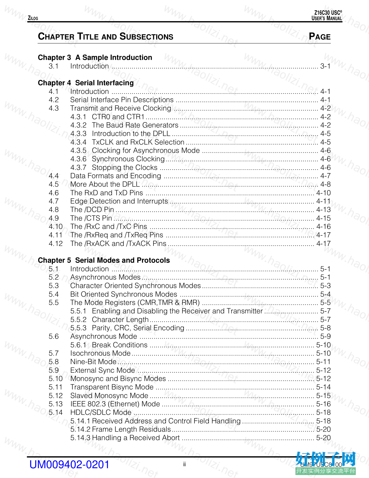
Chapter 3 A Sample Introduction
3.1 Introduction ....................................................................................................... 3-1
Chapter 4 Serial Interfacing
4.1 Introduction ....................................................................................................... 4-1
4.2 Serial Interface Pin Descriptions ....................................................................... 4-1
4.3 Transmit and Receive Clocking ........................................................................ 4-2
4.3.1 CTR0 and CTR1...................................................................................... 4-2
4.3.2 The Baud Rate Generators..................................................................... 4-2
4.3.3 Introduction to the DPLL......................................................................... 4-5
4.3.4 TxCLK and RxCLK Selection.................................................................. 4-5
4.3.5 Clocking for Asynchronous Mode .......................................................... 4-6
4.3.6 Synchronous Clocking............................................................................ 4-6
4.3.7 Stopping the Clocks ............................................................................... 4-6
4.4 Data Formats and Encoding ............................................................................. 4-7
4.5 More About the DPLL ........................................................................................ 4-8
4.6 The RxD and TxD Pins .................................................................................... 4-10
4.7 Edge Detection and Interrupts ........................................................................ 4-11
4.8 The /DCD Pin................................................................................................... 4-13
4.9 The /CTS Pin.................................................................................................... 4-15
4.10 The /RxC and /TxC Pins .................................................................................. 4-16
4.11 The /RxReq and /TxReq Pins .......................................................................... 4-17
4.12 The /RxACK and /TxACK Pins......................................................................... 4-17
Chapter 5 Serial Modes and Protocols
5.1 Introduction ....................................................................................................... 5-1
5.2 Asynchronous Modes........................................................................................ 5-1
5.3 Character Oriented Synchronous Modes.......................................................... 5-3
5.4 Bit Oriented Synchronous Modes ..................................................................... 5-4
5.5 The Mode Registers (CMR,TMR & RMR) .......................................................... 5-5
5.5.1 Enabling and Disabling the Receiver and Transmitter........................... 5-7
5.5.2 Character Length.................................................................................... 5-7
5.5.3 Parity, CRC, Serial Encoding.................................................................. 5-8
5.6 Asynchronous Mode ......................................................................................... 5-9
5.6.1 Break Conditions .................................................................................. 5-10
5.7 Isochronous Mode........................................................................................... 5-10
5.8 Nine-Bit Mode.................................................................................................. 5-11
5.9 External Sync Mode ........................................................................................ 5-12
5.10 Monosync and Bisync Modes ......................................................................... 5-12
5.11 Transparent Bisync Mode ............................................................................... 5-14
5.12 Slaved Monosync Mode.................................................................................. 5-15
5.13 IEEE 802.3 (Ethernet) Mode ............................................................................ 5-16
5.14 HDLC/SDLC Mode .......................................................................................... 5-18
5.14.1 Received Address and Control Field Handling.................................... 5-18
5.14.2 Frame Length Residuals....................................................................... 5-20
5.14.3 Handling a Received Abort .................................................................. 5-20
UM009402-0201
Z16C30 USC ®
U SER ' S M ANUAL
iii
Z ILOG
UM97USC0100
C HAPTER T ITLE AND S UBSECTIONS P AGE
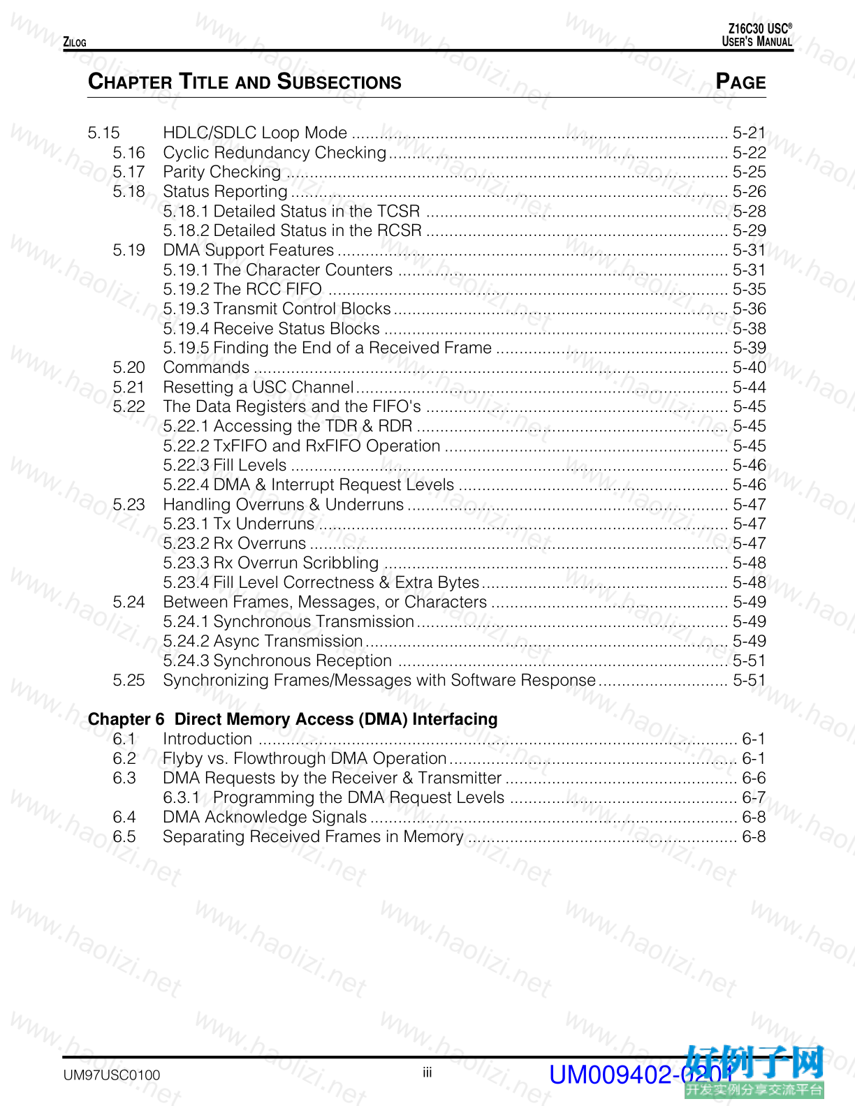
5.15 HDLC/SDLC Loop Mode ................................................................................. 5-21
5.16 Cyclic Redundancy Checking......................................................................... 5-22
5.17 Parity Checking ............................................................................................... 5-25
5.18 Status Reporting.............................................................................................. 5-26
5.18.1 Detailed Status in the TCSR ................................................................. 5-28
5.18.2 Detailed Status in the RCSR ................................................................. 5-29
5.19 DMA Support Features.................................................................................... 5-31
5.19.1 The Character Counters ....................................................................... 5-31
5.19.2 The RCC FIFO ...................................................................................... 5-35
5.19.3 Transmit Control Blocks........................................................................ 5-36
5.19.4 Receive Status Blocks .......................................................................... 5-38
5.19.5 Finding the End of a Received Frame .................................................. 5-39
5.20 Commands ...................................................................................................... 5-40
5.21 Resetting a USC Channel................................................................................ 5-44
5.22 The Data Registers and the FIFO's ................................................................. 5-45
5.22.1 Accessing the TDR & RDR ................................................................... 5-45
5.22.2 TxFIFO and RxFIFO Operation ............................................................. 5-45
5.22.3 Fill Levels .............................................................................................. 5-46
5.22.4 DMA & Interrupt Request Levels .......................................................... 5-46
5.23 Handling Overruns & Underruns..................................................................... 5-47
5.23.1 Tx Underruns ........................................................................................ 5-47
5.23.2 Rx Overruns.......................................................................................... 5-47
5.23.3 Rx Overrun Scribbling .......................................................................... 5-48
5.23.4 Fill Level Correctness & Extra Bytes..................................................... 5-48
5.24 Between Frames, Messages, or Characters ................................................... 5-49
5.24.1 Synchronous Transmission................................................................... 5-49
5.24.2 Async Transmission.............................................................................. 5-49
5.24.3 Synchronous Reception ....................................................................... 5-51
5.25 Synchronizing Frames/Messages with Software Response............................ 5-51
Chapter 6 Direct Memory Access (DMA) Interfacing
6.1 Introduction ....................................................................................................... 6-1
6.2 Flyby vs. Flowthrough DMA Operation.............................................................. 6-1
6.3 DMA Requests by the Receiver & Transmitter.................................................. 6-6
6.3.1 Programming the DMA Request Levels ................................................. 6-7
6.4 DMA Acknowledge Signals............................................................................... 6-8
6.5 Separating Received Frames in Memory .......................................................... 6-8
UM009402-0201
Z16C30 USC ®
U SER ' S M ANUAL
iv
Z ILOG
UM97USC0100
C HAPTER T ITLE AND S UBSECTIONS P AGE
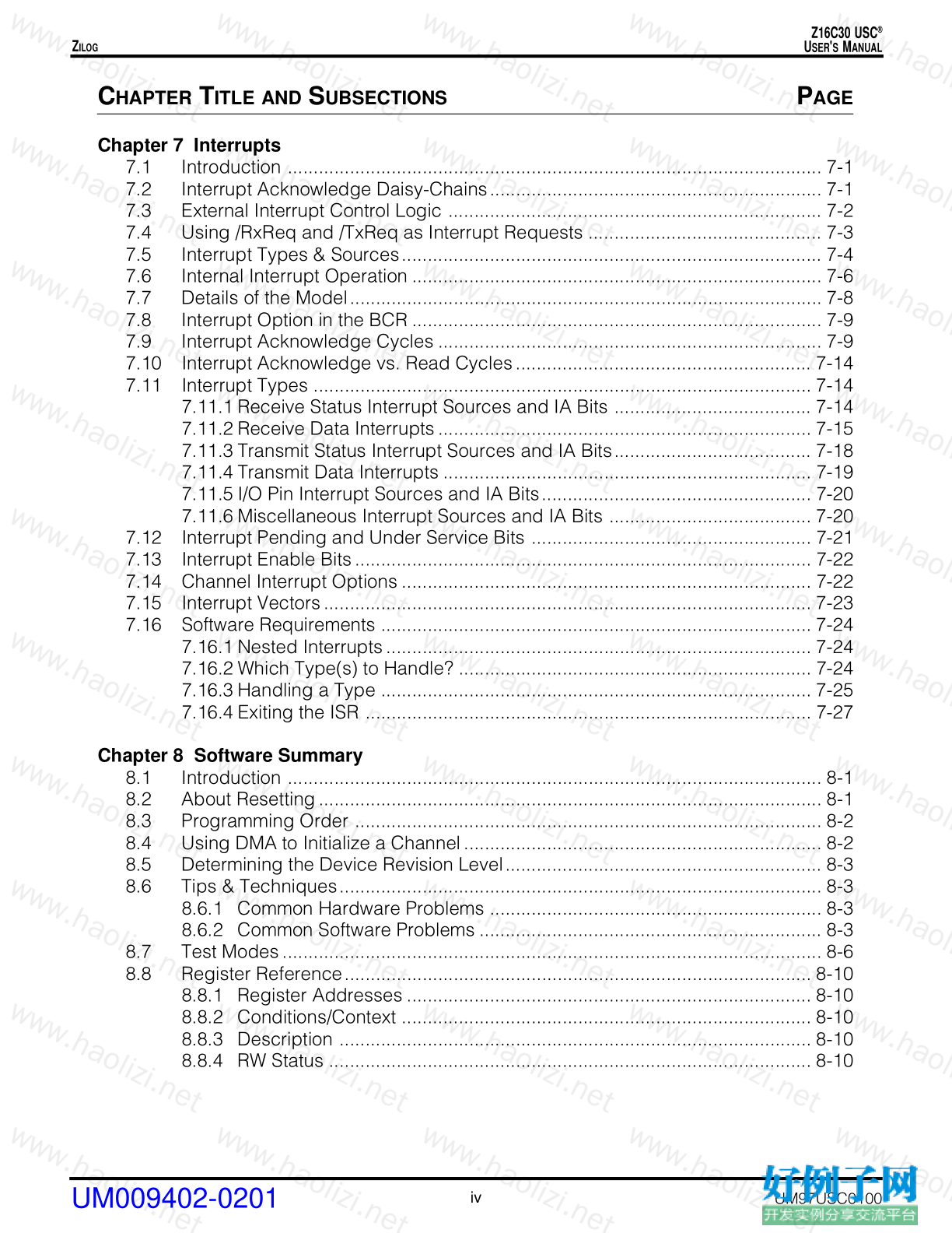
Chapter 7 Interrupts
7.1 Introduction ....................................................................................................... 7-1
7.2 Interrupt Acknowledge Daisy-Chains................................................................ 7-1
7.3 External Interrupt Control Logic ........................................................................ 7-2
7.4 Using /RxReq and /TxReq as Interrupt Requests ............................................. 7-3
7.5 Interrupt Types & Sources................................................................................. 7-4
7.6 Internal Interrupt Operation ............................................................................... 7-6
7.7 Details of the Model........................................................................................... 7-8
7.8 Interrupt Option in the BCR ............................................................................... 7-9
7.9 Interrupt Acknowledge Cycles .......................................................................... 7-9
7.10 Interrupt Acknowledge vs. Read Cycles......................................................... 7-14
7.11 Interrupt Types ................................................................................................ 7-14
7.11.1 Receive Status Interrupt Sources and IA Bits ...................................... 7-14
7.11.2 Receive Data Interrupts........................................................................ 7-15
7.11.3 Transmit Status Interrupt Sources and IA Bits...................................... 7-18
7.11.4 Transmit Data Interrupts ....................................................................... 7-19
7.11.5 I/O Pin Interrupt Sources and IA Bits.................................................... 7-20
7.11.6 Miscellaneous Interrupt Sources and IA Bits ....................................... 7-20
7.12 Interrupt Pending and Under Service Bits ...................................................... 7-21
7.13 Interrupt Enable Bits........................................................................................ 7-22
7.14 Channel Interrupt Options ............................................................................... 7-22
7.15 Interrupt Vectors.............................................................................................. 7-23
7.16 Software Requirements ................................................................................... 7-24
7.16.1 Nested Interrupts.................................................................................. 7-24
7.16.2 Which Type(s) to Handle? .................................................................... 7-24
7.16.3 Handling a Type ................................................................................... 7-25
7.16.4 Exiting the ISR ...................................................................................... 7-27
Chapter 8 Software Summary
8.1 Introduction ....................................................................................................... 8-1
8.2 About Resetting................................................................................................. 8-1
8.3 Programming Order .......................................................................................... 8-2
8.4 Using DMA to Initialize a Channel..................................................................... 8-2
8.5 Determining the Device Revision Level............................................................. 8-3
8.6 Tips & Techniques............................................................................................. 8-3
8.6.1 Common Hardware Problems ................................................................ 8-3
8.6.2 Common Software Problems .................................................................. 8-3
8.7 Test Modes........................................................................................................ 8-6
8.8 Register Reference.......................................................................................... 8-10
8.8.1 Register Addresses .............................................................................. 8-10
8.8.2 Conditions/Context ............................................................................... 8-10
8.8.3 Description ........................................................................................... 8-10
8.8.4 RW Status ............................................................................................. 8-10
UM009402-0201
Z16C30 USC ®
U SER ' S M ANUAL
v
Z ILOG
UM97USC0100
C HAPTER T ITLE AND S UBSECTIONS P AGE
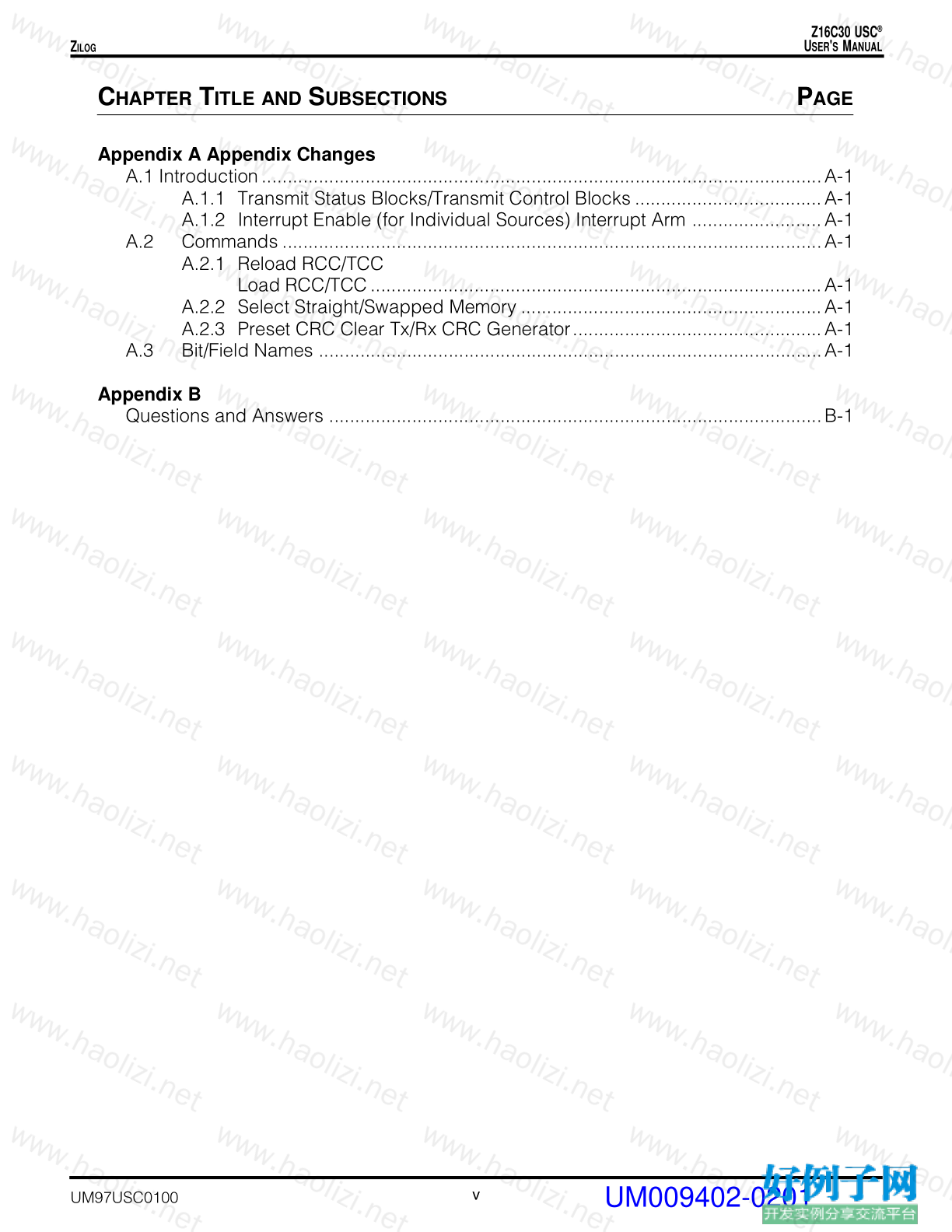
Appendix A Appendix Changes
A.1 Introduction............................................................................................................A-1
A.1.1 Transmit Status Blocks/Transmit Control Blocks ....................................A-1
A.1.2 Interrupt Enable (for Individual Sources) Interrupt Arm .........................A-1
A.2 Commands ........................................................................................................A-1
A.2.1 Reload RCC/TCC
Load RCC/TCC.......................................................................................A-1
A.2.2 Select Straight/Swapped Memory ..........................................................A-1
A.2.3 Preset CRC Clear Tx/Rx CRC Generator................................................A-1
A.3 Bit/Field Names .................................................................................................A-1
Appendix B
Questions and Answers ...............................................................................................B-1
UM009402-0201
Z16C30 USC ®
U SER ' S M ANUAL
vi
Z ILOG
UM97USC0100
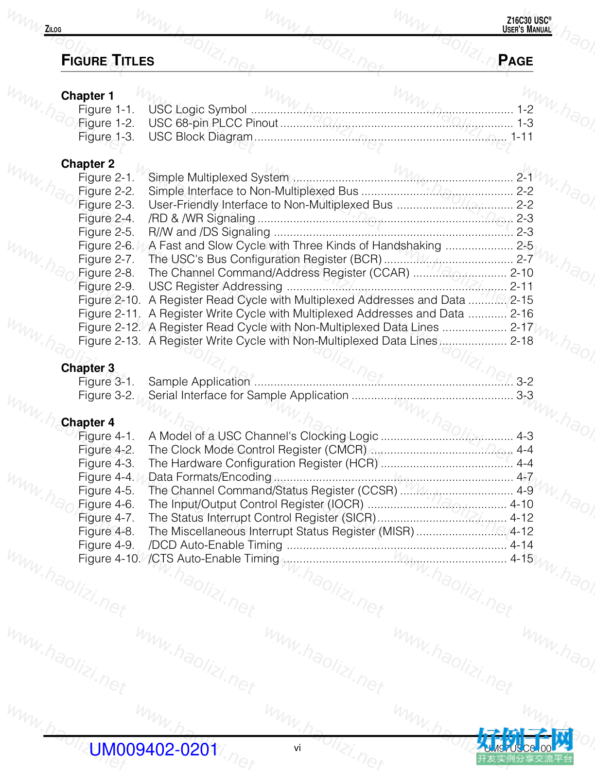
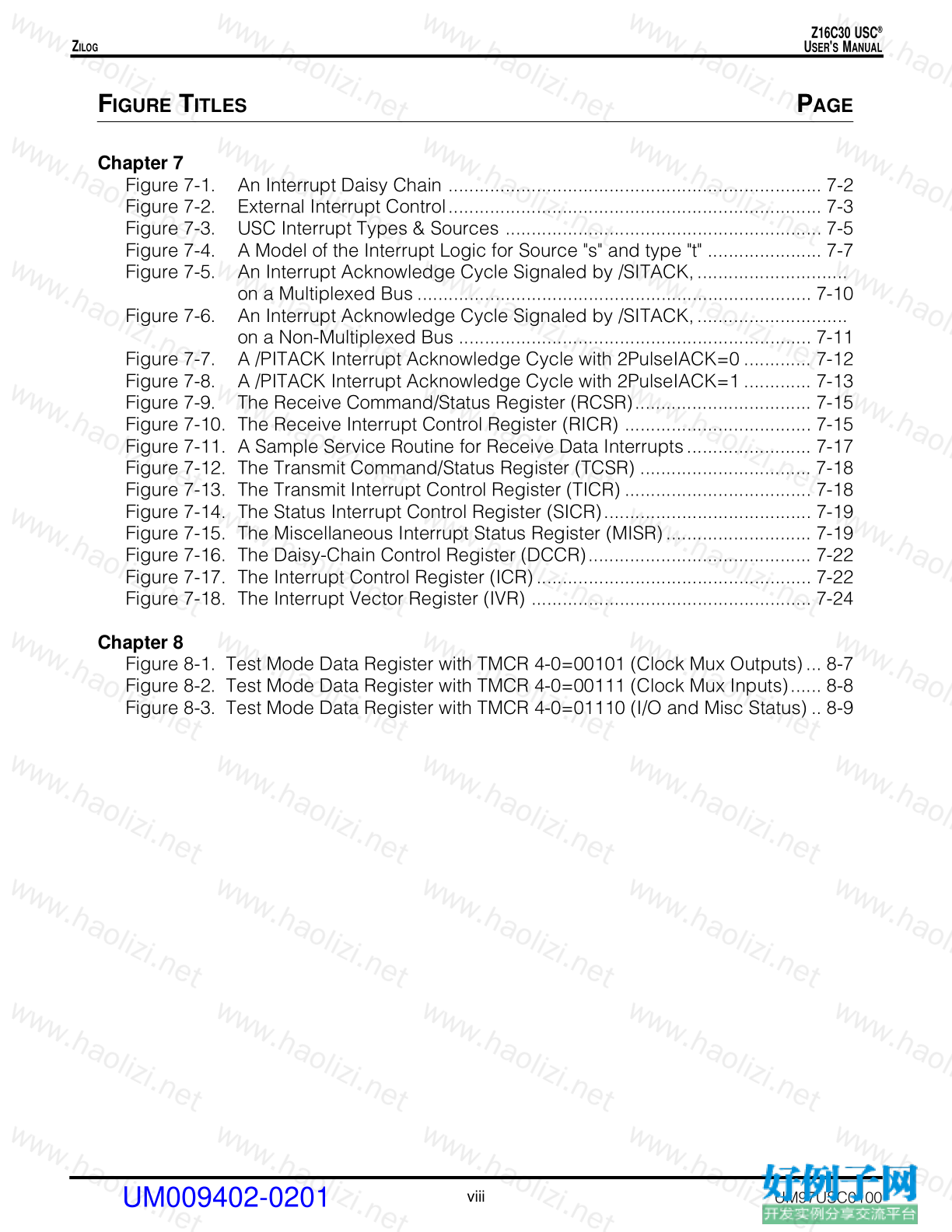
F IGURE T ITLES P AGE
Chapter 1
Figure 1-1. USC Logic Symbol ................................................................................. 1-2
Figure 1-2. USC 68-pin PLCC Pinout........................................................................ 1-3
Figure 1-3. USC Block Diagram.............................................................................. 1-11
Chapter 2
Figure 2-1. Simple Multiplexed System .................................................................... 2-1
Figure 2-2. Simple Interface to Non-Multiplexed Bus ............................................... 2-2
Figure 2-3. User-Friendly Interface to Non-Multiplexed Bus .................................... 2-2
Figure 2-4. /RD & /WR Signaling............................................................................... 2-3
Figure 2-5. R//W and /DS Signaling .......................................................................... 2-3
Figure 2-6. A Fast and Slow Cycle with Three Kinds of Handshaking ..................... 2-5
Figure 2-7. The USC's Bus Configuration Register (BCR)........................................ 2-7
Figure 2-8. The Channel Command/Address Register (CCAR) ............................. 2-10
Figure 2-9. USC Register Addressing .................................................................... 2-11
Figure 2-10. A Register Read Cycle with Multiplexed Addresses and Data ............ 2-15
Figure 2-11. A Register Write Cycle with Multiplexed Addresses and Data ............ 2-16
Figure 2-12. A Register Read Cycle with Non-Multiplexed Data Lines .................... 2-17
Figure 2-13. A Register Write Cycle with Non-Multiplexed Data Lines..................... 2-18
Chapter 3
Figure 3-1. Sample Application ................................................................................ 3-2
Figure 3-2. Serial Interface for Sample Application .................................................. 3-3
Chapter 4
Figure 4-1. A Model of a USC Channel's Clocking Logic......................................... 4-3
Figure 4-2. The Clock Mode Control Register (CMCR) ............................................ 4-4
Figure 4-3. The Hardware Configuration Register (HCR) ......................................... 4-4
Figure 4-4. Data Formats/Encoding.......................................................................... 4-7
Figure 4-5. The Channel Command/Status Register (CCSR) ................................... 4-9
Figure 4-6. The Input/Output Control Register (IOCR) ........................................... 4-10
Figure 4-7. The Status Interrupt Control Register (SICR)........................................ 4-12
Figure 4-8. The Miscellaneous Interrupt Status Register (MISR)............................ 4-12
Figure 4-9. /DCD Auto-Enable Timing .................................................................... 4-14
Figure 4-10. /CTS Auto-Enable Timing ..................................................................... 4-15
UM009402-0201
Z16C30 USC ®
U SER ' S M ANUAL
vii
Z ILOG
UM97USC0100
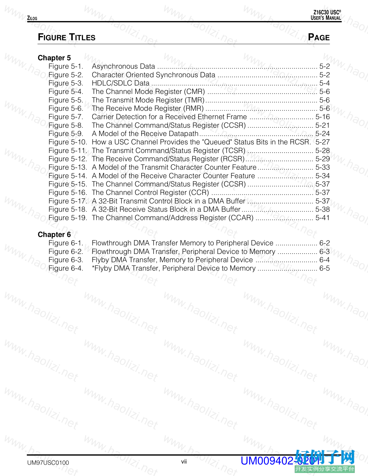
F IGURE T ITLES P AGE
Chapter 5
Figure 5-1. Asynchronous Data ................................................................................ 5-2
Figure 5-2. Character Oriented Synchronous Data .................................................. 5-2
Figure 5-3. HDLC/SDLC Data ................................................................................... 5-4
Figure 5-4. The Channel Mode Register (CMR) ....................................................... 5-6
Figure 5-5. The Transmit Mode Register (TMR)........................................................ 5-6
Figure 5-6. The Receive Mode Register (RMR) ........................................................ 5-6
Figure 5-7. Carrier Detection for a Received Ethernet Frame ................................ 5-16
Figure 5-8. The Channel Command/Status Register (CCSR) ................................. 5-21
Figure 5-9. A Model of the Receive Datapath......................................................... 5-24
Figure 5-10. How a USC Channel Provides the "Queued" Status Bits in the RCSR. 5-27
Figure 5-11. The Transmit Command/Status Register (TCSR) ................................. 5-28
Figure 5-12. The Receive Command/Status Register (RCSR).................................. 5-29
Figure 5-13. A Model of the Transmit Character Counter Feature............................ 5-33
Figure 5-14. A Model of the Receive Character Counter Feature ............................ 5-34
Figure 5-15. The Channel Command/Status Register (CCSR) ................................. 5-37
Figure 5-16. The Channel Control Register (CCR) ................................................... 5-37
Figure 5-17. A 32-Bit Transmit Control Block in a DMA Buffer ................................. 5-37
Figure 5-18. A 32-Bit Receive Status Block in a DMA Buffer.................................... 5-38
Figure 5-19. The Channel Command/Address Register (CCAR) ............................. 5-41
Chapter 6
Figure 6-1. Flowthrough DMA Transfer Memory to Peripheral Device ..................... 6-2
Figure 6-2. Flowthrough DMA Transfer, Peripheral Device to Memory .................... 6-3
Figure 6-3. Flyby DMA Transfer, Memory to Peripheral Device ............................... 6-4
Figure 6-4. *Flyby DMA Transfer, Peripheral Device to Memory .............................. 6-5
UM009402-0201
Z16C30 USC ®
U SER ' S M ANUAL
viii
Z ILOG
UM97USC0100
F IGURE T ITLES P AGE
Chapter 7
Figure 7-1. An Interrupt Daisy Chain ........................................................................ 7-2
Figure 7-2. External Interrupt Control........................................................................ 7-3
Figure 7-3. USC Interrupt Types & Sources ............................................................. 7-5
Figure 7-4. A Model of the Interrupt Logic for Source "s" and type "t" ...................... 7-7
Figure 7-5. An Interrupt Acknowledge Cycle Signaled by /SITACK,.............................
on a Multiplexed Bus ............................................................................ 7-10
Figure 7-6. An Interrupt Acknowledge Cycle Signaled by /SITACK,.............................
on a Non-Multiplexed Bus .................................................................... 7-11
Figure 7-7. A /PITACK Interrupt Acknowledge Cycle with 2PulseIACK=0 ............. 7-12
Figure 7-8. A /PITACK Interrupt Acknowledge Cycle with 2PulseIACK=1 ............. 7-13
Figure 7-9. The Receive Command/Status Register (RCSR).................................. 7-15
Figure 7-10. The Receive Interrupt Control Register (RICR) .................................... 7-15
Figure 7-11. A Sample Service Routine for Receive Data Interrupts........................ 7-17
Figure 7-12. The Transmit Command/Status Register (TCSR) ................................. 7-18
Figure 7-13. The Transmit Interrupt Control Register (TICR) .................................... 7-18
Figure 7-14. The Status Interrupt Control Register (SICR)........................................ 7-19
Figure 7-15. The Miscellaneous Interrupt Status Register (MISR)............................ 7-19
Figure 7-16. The Daisy-Chain Control Register (DCCR)........................................... 7-22
Figure 7-17. The Interrupt Control Register (ICR)..................................................... 7-22
Figure 7-18. The Interrupt Vector Register (IVR) ...................................................... 7-24
Chapter 8
Figure 8-1. Test Mode Data Register with TMCR 4-0=00101 (Clock Mux Outputs)... 8-7
Figure 8-2. Test Mode Data Register with TMCR 4-0=00111 (Clock Mux Inputs)...... 8-8
Figure 8-3. Test Mode Data Register with TMCR 4-0=01110 (I/O and Misc Status) .. 8-9
UM009402-0201
Z16C30 USC ®
U SER ' S M ANUAL
ix
Z ILOG
UM97USC0100
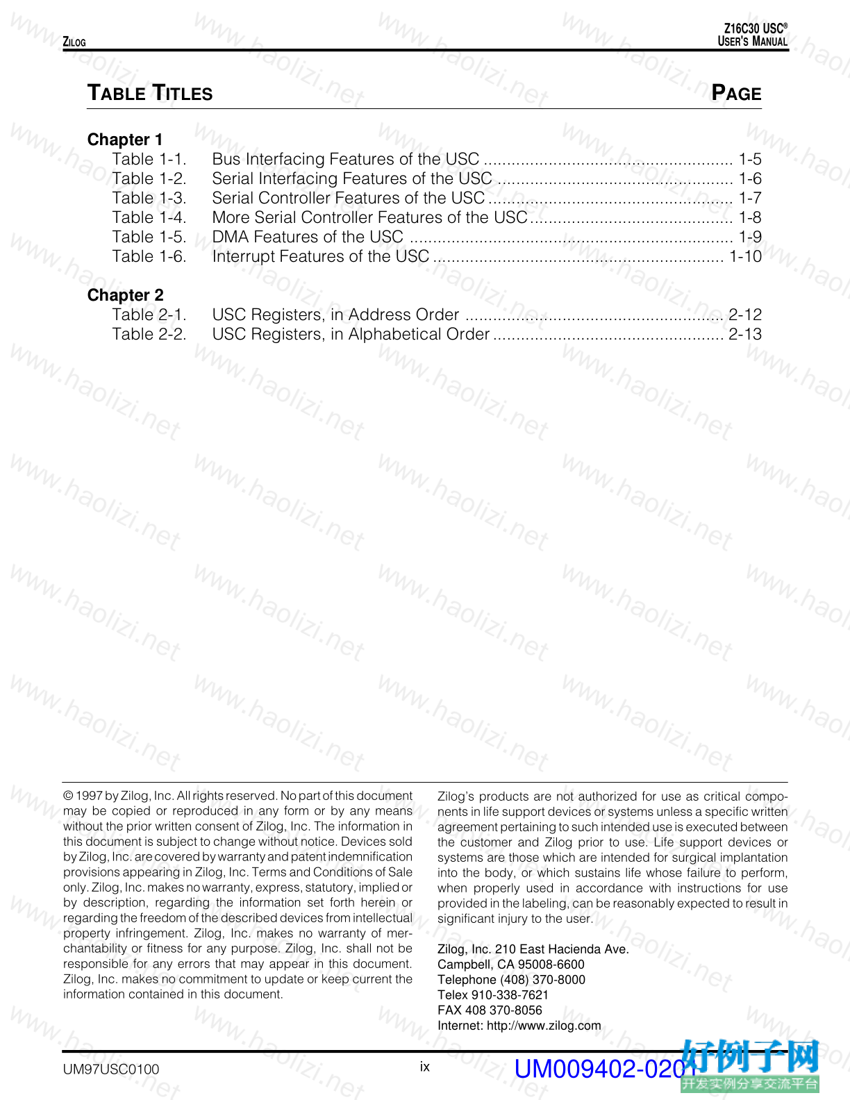
T ABLE T ITLES P AGE
Chapter 1
Table 1-1. Bus Interfacing Features of the USC ...................................................... 1-5
Table 1-2. Serial Interfacing Features of the USC ................................................... 1-6
Table 1-3. Serial Controller Features of the USC..................................................... 1-7
Table 1-4. More Serial Controller Features of the USC............................................ 1-8
Table 1-5. DMA Features of the USC ...................................................................... 1-9
Table 1-6. Interrupt Features of the USC............................................................... 1-10
Chapter 2
Table 2-1. USC Registers, in Address Order ........................................................ 2-12
Table 2-2. USC Registers, in Alphabetical Order.................................................. 2-13
小贴士
感谢您为本站写下的评论,您的评论对其它用户来说具有重要的参考价值,所以请认真填写。
- 类似“顶”、“沙发”之类没有营养的文字,对勤劳贡献的楼主来说是令人沮丧的反馈信息。
- 相信您也不想看到一排文字/表情墙,所以请不要反馈意义不大的重复字符,也请尽量不要纯表情的回复。
- 提问之前请再仔细看一遍楼主的说明,或许是您遗漏了。
- 请勿到处挖坑绊人、招贴广告。既占空间让人厌烦,又没人会搭理,于人于己都无利。
关于好例子网
本站旨在为广大IT学习爱好者提供一个非营利性互相学习交流分享平台。本站所有资源都可以被免费获取学习研究。本站资源来自网友分享,对搜索内容的合法性不具有预见性、识别性、控制性,仅供学习研究,请务必在下载后24小时内给予删除,不得用于其他任何用途,否则后果自负。基于互联网的特殊性,平台无法对用户传输的作品、信息、内容的权属或合法性、安全性、合规性、真实性、科学性、完整权、有效性等进行实质审查;无论平台是否已进行审查,用户均应自行承担因其传输的作品、信息、内容而可能或已经产生的侵权或权属纠纷等法律责任。本站所有资源不代表本站的观点或立场,基于网友分享,根据中国法律《信息网络传播权保护条例》第二十二与二十三条之规定,若资源存在侵权或相关问题请联系本站客服人员,点此联系我们。关于更多版权及免责申明参见 版权及免责申明


网友评论
我要评论