【实例简介】Rockchip RK3399 TRM Part1(瑞芯微 RK3399 TRM Part1)
Rockchip_RK3399TRM_V1.4_Part1-20170408.pdf
【实例截图】
【核心代码】
Table of Content
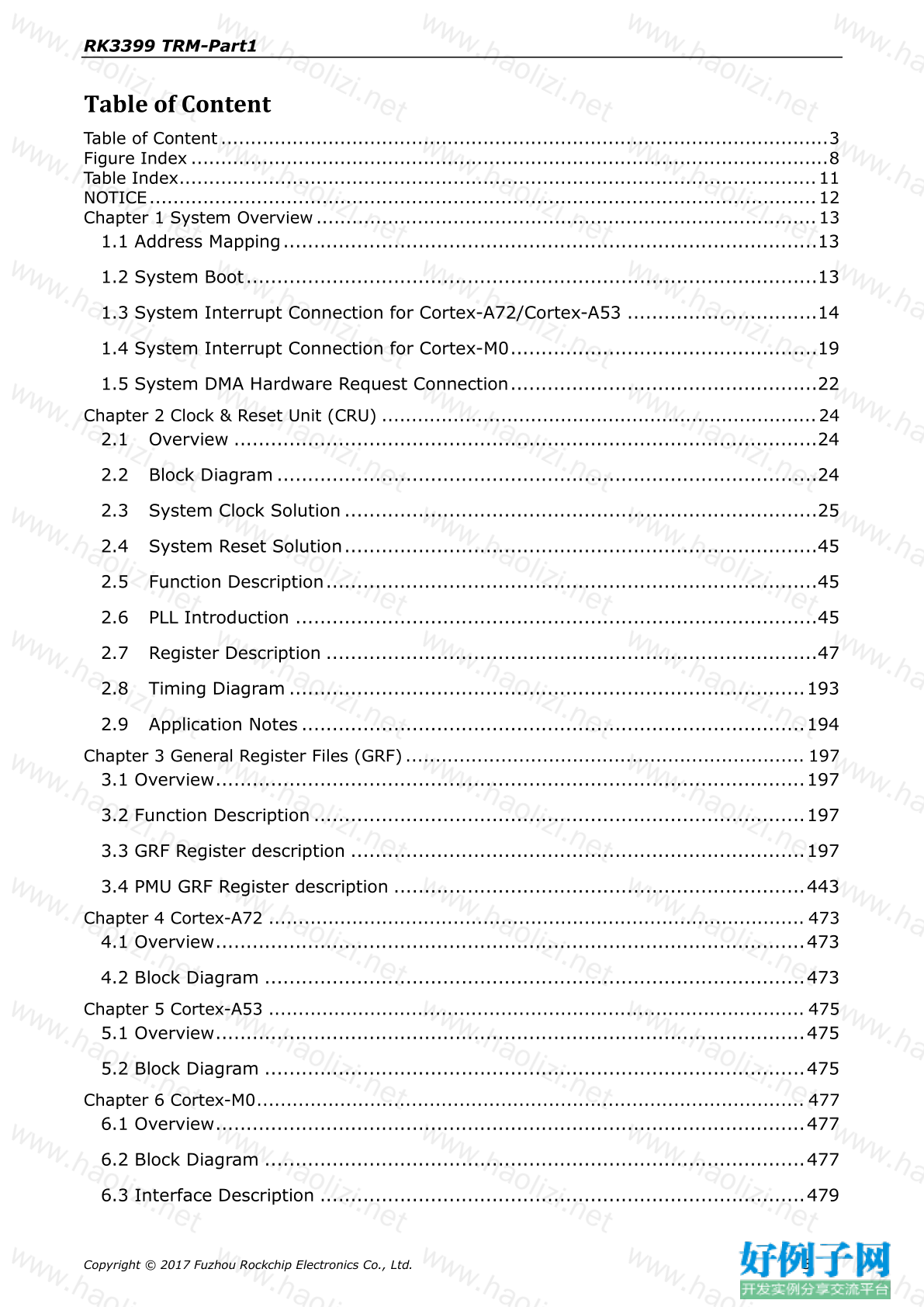
Table of Content......................................................................................................3
Figure Index ...........................................................................................................8
Table Index...........................................................................................................11
NOTICE................................................................................................................12
Chapter 1 System Overview ....................................................................................13
1.1 Address Mapping.......................................................................................13
1.2 System Boot.............................................................................................13
1.3 System Interrupt Connection for Cortex-A72/Cortex-A53 ...............................14
1.4 System Interrupt Connection for Cortex-M0..................................................19
1.5 System DMA Hardware Request Connection..................................................22
Chapter 2 Clock & Reset Unit (CRU) .........................................................................24
2.1 Overview ...............................................................................................24
2.2 Block Diagram ........................................................................................24
2.3 System Clock Solution .............................................................................25
2.4 System Reset Solution.............................................................................45
2.5 Function Description................................................................................45
2.6 PLL Introduction .....................................................................................45
2.7 Register Description ................................................................................47
2.8 Timing Diagram ....................................................................................193
2.9 Application Notes ..................................................................................194
Chapter 3 General Register Files (GRF) ................................................................... 197
3.1 Overview................................................................................................197
3.2 Function Description ................................................................................197
3.3 GRF Register description ..........................................................................197
3.4 PMU GRF Register description ...................................................................443
Chapter 4 Cortex-A72 .......................................................................................... 473
4.1 Overview................................................................................................473
4.2 Block Diagram ........................................................................................473
Chapter 5 Cortex-A53 .......................................................................................... 475
5.1 Overview................................................................................................475
5.2 Block Diagram ........................................................................................475
Chapter 6 Cortex-M0............................................................................................ 477
6.1 Overview................................................................................................477
6.2 Block Diagram ........................................................................................477
6.3 Interface Description ...............................................................................479
Copyright © 2017 Fuzhou Rockchip Electronics Co., Ltd. 3RK3399 TRM-Part1
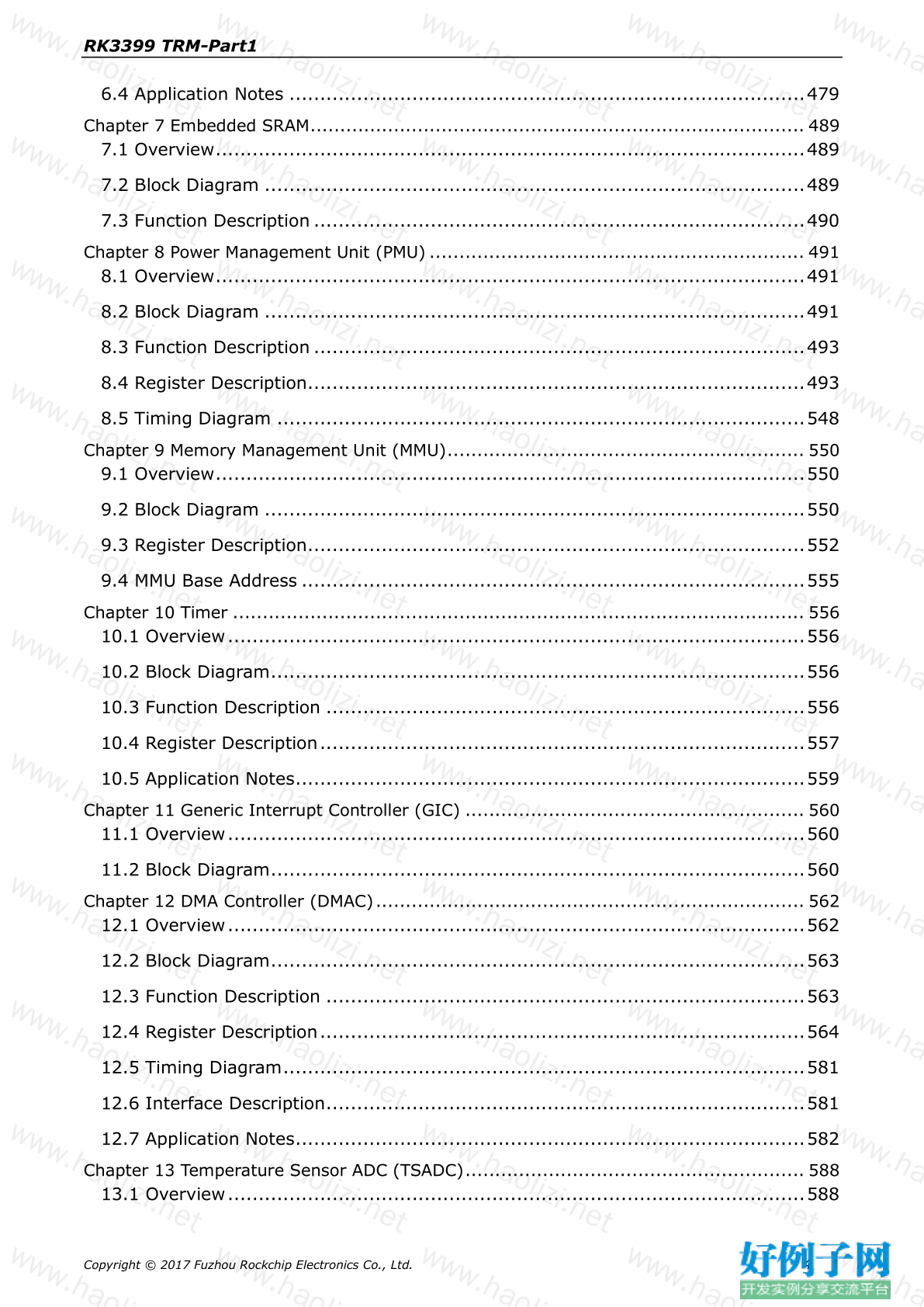
6.4 Application Notes ....................................................................................479
Chapter 7 Embedded SRAM................................................................................... 489
7.1 Overview................................................................................................489
7.2 Block Diagram ........................................................................................489
7.3 Function Description ................................................................................490
Chapter 8 Power Management Unit (PMU) ............................................................... 491
8.1 Overview................................................................................................491
8.2 Block Diagram ........................................................................................491
8.3 Function Description ................................................................................493
8.4 Register Description.................................................................................493
8.5 Timing Diagram ......................................................................................548
Chapter 9 Memory Management Unit (MMU)............................................................ 550
9.1 Overview................................................................................................550
9.2 Block Diagram ........................................................................................550
9.3 Register Description.................................................................................552
9.4 MMU Base Address ..................................................................................555
Chapter 10 Timer ................................................................................................ 556
10.1 Overview..............................................................................................556
10.2 Block Diagram.......................................................................................556
10.3 Function Description ..............................................................................556
10.4 Register Description...............................................................................557
10.5 Application Notes...................................................................................559
Chapter 11 Generic Interrupt Controller (GIC) ......................................................... 560
11.1 Overview..............................................................................................560
11.2 Block Diagram.......................................................................................560
Chapter 12 DMA Controller (DMAC) ........................................................................ 562
12.1 Overview..............................................................................................562
12.2 Block Diagram.......................................................................................563
12.3 Function Description ..............................................................................563
12.4 Register Description...............................................................................564
12.5 Timing Diagram.....................................................................................581
12.6 Interface Description..............................................................................581
12.7 Application Notes...................................................................................582
Chapter 13 Temperature Sensor ADC (TSADC)......................................................... 588
13.1 Overview..............................................................................................588
Copyright © 2017 Fuzhou Rockchip Electronics Co., Ltd. 4RK3399 TRM-Part1
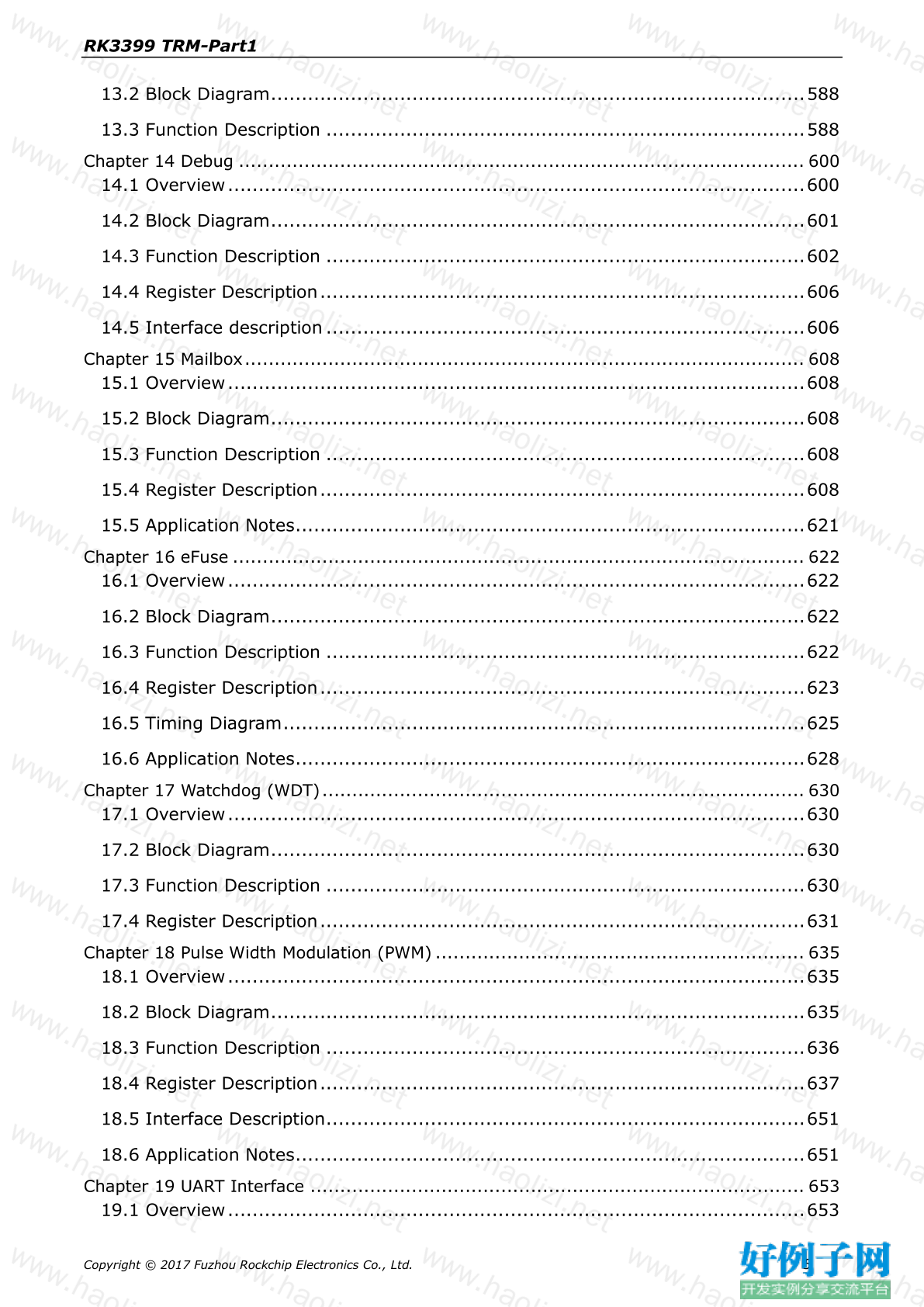
13.2 Block Diagram.......................................................................................588
13.3 Function Description ..............................................................................588
Chapter 14 Debug ............................................................................................... 600
14.1 Overview..............................................................................................600
14.2 Block Diagram.......................................................................................601
14.3 Function Description ..............................................................................602
14.4 Register Description...............................................................................606
14.5 Interface description ..............................................................................606
Chapter 15 Mailbox.............................................................................................. 608
15.1 Overview..............................................................................................608
15.2 Block Diagram.......................................................................................608
15.3 Function Description ..............................................................................608
15.4 Register Description...............................................................................608
15.5 Application Notes...................................................................................621
Chapter 16 eFuse ................................................................................................ 622
16.1 Overview..............................................................................................622
16.2 Block Diagram.......................................................................................622
16.3 Function Description ..............................................................................622
16.4 Register Description...............................................................................623
16.5 Timing Diagram.....................................................................................625
16.6 Application Notes...................................................................................628
Chapter 17 Watchdog (WDT) ................................................................................. 630
17.1 Overview..............................................................................................630
17.2 Block Diagram.......................................................................................630
17.3 Function Description ..............................................................................630
17.4 Register Description...............................................................................631
Chapter 18 Pulse Width Modulation (PWM) .............................................................. 635
18.1 Overview..............................................................................................635
18.2 Block Diagram.......................................................................................635
18.3 Function Description ..............................................................................636
18.4 Register Description...............................................................................637
18.5 Interface Description..............................................................................651
18.6 Application Notes...................................................................................651
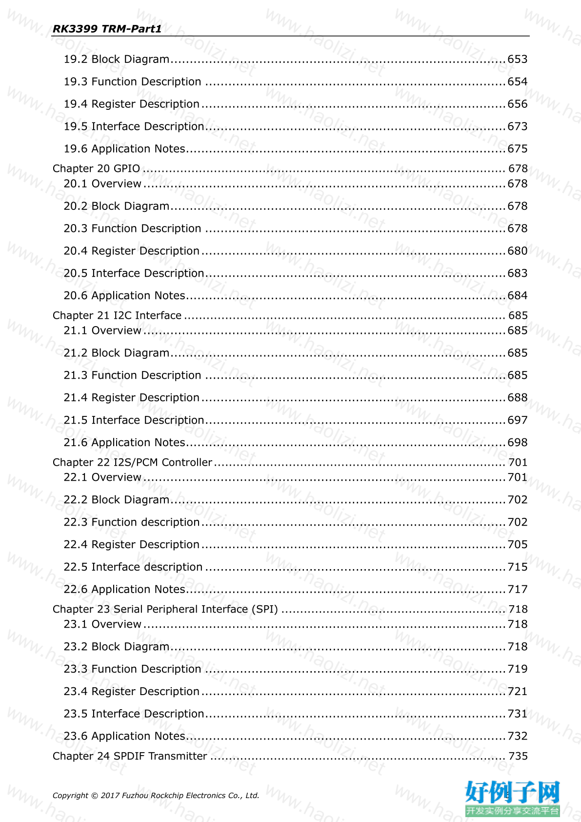
Chapter 19 UART Interface ................................................................................... 653
19.1 Overview..............................................................................................653
Copyright © 2017 Fuzhou Rockchip Electronics Co., Ltd. 5RK3399 TRM-Part1
19.2 Block Diagram.......................................................................................653
19.3 Function Description ..............................................................................654
19.4 Register Description...............................................................................656
19.5 Interface Description..............................................................................673
19.6 Application Notes...................................................................................675
Chapter 20 GPIO ................................................................................................. 678
20.1 Overview..............................................................................................678
20.2 Block Diagram.......................................................................................678
20.3 Function Description ..............................................................................678
20.4 Register Description...............................................................................680
20.5 Interface Description..............................................................................683
20.6 Application Notes...................................................................................684
Chapter 21 I2C Interface ...................................................................................... 685
21.1 Overview..............................................................................................685
21.2 Block Diagram.......................................................................................685
21.3 Function Description ..............................................................................685
21.4 Register Description...............................................................................688
21.5 Interface Description..............................................................................697
21.6 Application Notes...................................................................................698
Chapter 22 I2S/PCM Controller .............................................................................. 701
22.1 Overview..............................................................................................701
22.2 Block Diagram.......................................................................................702
22.3 Function description...............................................................................702
22.4 Register Description...............................................................................705
22.5 Interface description ..............................................................................715
22.6 Application Notes...................................................................................717
Chapter 23 Serial Peripheral Interface (SPI) ............................................................ 718
23.1 Overview..............................................................................................718
23.2 Block Diagram.......................................................................................718
23.3 Function Description ..............................................................................719
23.4 Register Description...............................................................................721
23.5 Interface Description..............................................................................731
23.6 Application Notes...................................................................................732
Chapter 24 SPDIF Transmitter ............................................................................... 735
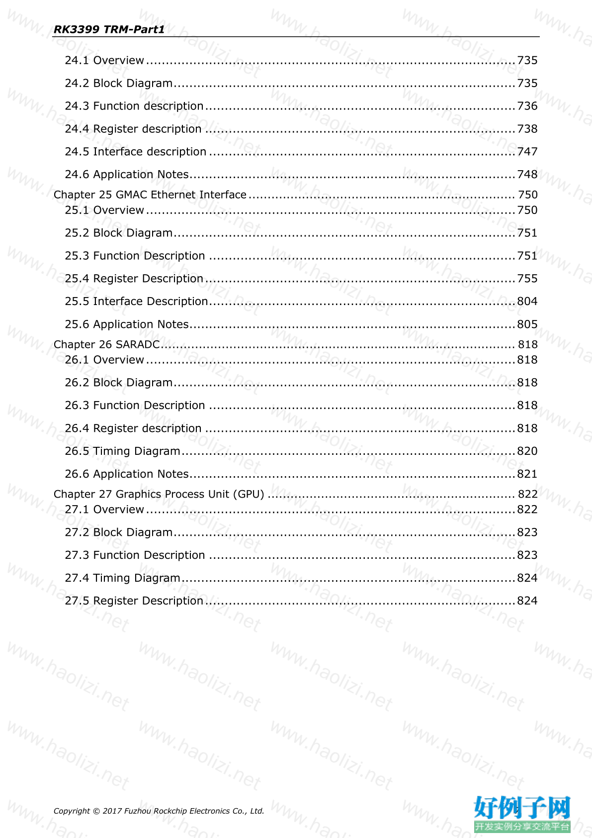
Copyright © 2017 Fuzhou Rockchip Electronics Co., Ltd. 6RK3399 TRM-Part1
24.1 Overview..............................................................................................735
24.2 Block Diagram.......................................................................................735
24.3 Function description...............................................................................736
24.4 Register description ...............................................................................738
24.5 Interface description ..............................................................................747
24.6 Application Notes...................................................................................748
Chapter 25 GMAC Ethernet Interface...................................................................... 750
25.1 Overview..............................................................................................750
25.2 Block Diagram.......................................................................................751
25.3 Function Description ..............................................................................751
25.4 Register Description...............................................................................755
25.5 Interface Description..............................................................................804
25.6 Application Notes...................................................................................805
Chapter 26 SARADC............................................................................................. 818
26.1 Overview..............................................................................................818
26.2 Block Diagram.......................................................................................818
26.3 Function Description ..............................................................................818
26.4 Register description ...............................................................................818
26.5 Timing Diagram.....................................................................................820
26.6 Application Notes...................................................................................821
Chapter 27 Graphics Process Unit (GPU) ................................................................. 822
27.1 Overview..............................................................................................822
27.2 Block Diagram.......................................................................................823
27.3 Function Description ..............................................................................823
27.4 Timing Diagram.....................................................................................824
27.5 Register Description...............................................................................824
Copyright © 2017 Fuzhou Rockchip Electronics Co., Ltd. 7RK3399 TRM-Part1
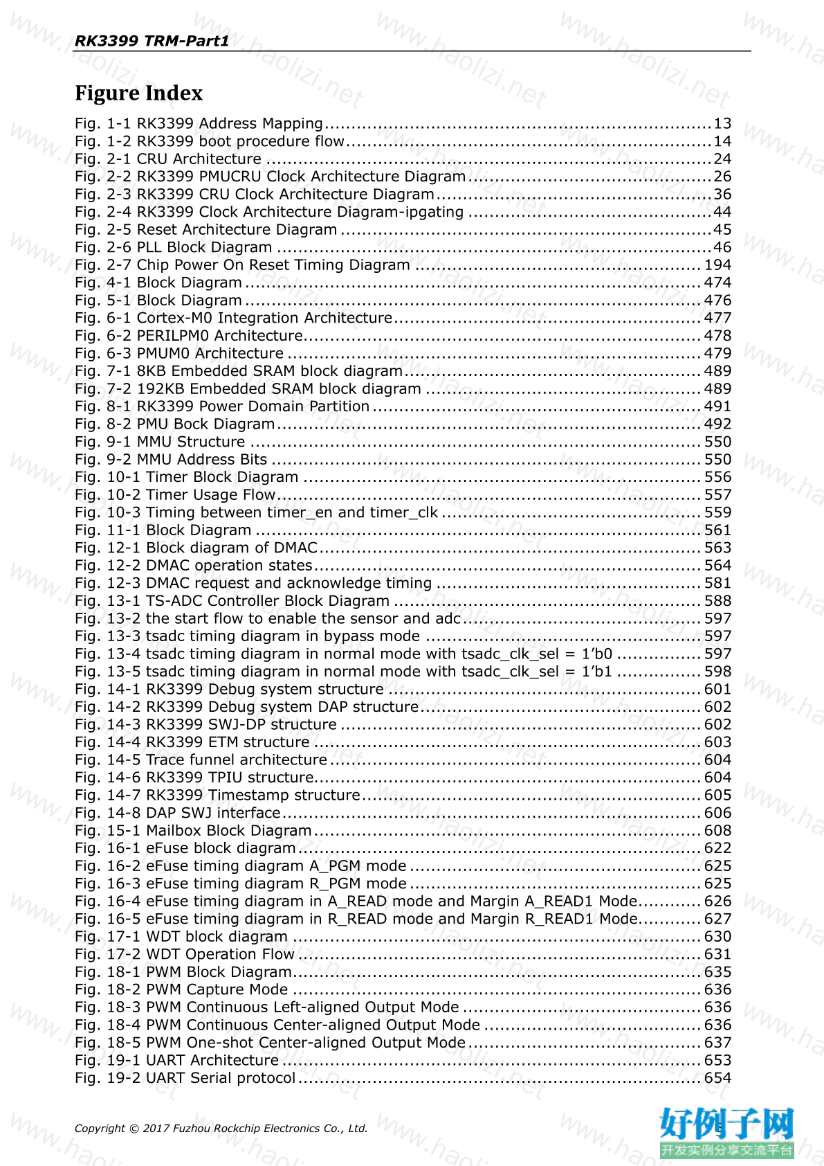
Figure Index
Fig. 1-1 RK3399 Address Mapping.........................................................................13
Fig. 1-2 RK3399 boot procedure flow.....................................................................14
Fig. 2-1 CRU Architecture ....................................................................................24
Fig. 2-2 RK3399 PMUCRU Clock Architecture Diagram..............................................26
Fig. 2-3 RK3399 CRU Clock Architecture Diagram....................................................36
Fig. 2-4 RK3399 Clock Architecture Diagram-ipgating ..............................................44
Fig. 2-5 Reset Architecture Diagram ......................................................................45
Fig. 2-6 PLL Block Diagram ..................................................................................46
Fig. 2-7 Chip Power On Reset Timing Diagram ...................................................... 194
Fig. 4-1 Block Diagram...................................................................................... 474
Fig. 5-1 Block Diagram...................................................................................... 476
Fig. 6-1 Cortex-M0 Integration Architecture.......................................................... 477
Fig. 6-2 PERILPM0 Architecture........................................................................... 478
Fig. 6-3 PMUM0 Architecture .............................................................................. 479
Fig. 7-1 8KB Embedded SRAM block diagram........................................................ 489
Fig. 7-2 192KB Embedded SRAM block diagram .................................................... 489
Fig. 8-1 RK3399 Power Domain Partition.............................................................. 491
Fig. 8-2 PMU Bock Diagram................................................................................ 492
Fig. 9-1 MMU Structure ..................................................................................... 550
Fig. 9-2 MMU Address Bits ................................................................................. 550
Fig. 10-1 Timer Block Diagram ........................................................................... 556
Fig. 10-2 Timer Usage Flow................................................................................ 557
Fig. 10-3 Timing between timer_en and timer_clk ................................................. 559
Fig. 11-1 Block Diagram .................................................................................... 561
Fig. 12-1 Block diagram of DMAC........................................................................ 563
Fig. 12-2 DMAC operation states......................................................................... 564
Fig. 12-3 DMAC request and acknowledge timing .................................................. 581
Fig. 13-1 TS-ADC Controller Block Diagram .......................................................... 588
Fig. 13-2 the start flow to enable the sensor and adc............................................. 597
Fig. 13-3 tsadc timing diagram in bypass mode .................................................... 597
Fig. 13-4 tsadc timing diagram in normal mode with tsadc_clk_sel = 1’b0 ................ 597
Fig. 13-5 tsadc timing diagram in normal mode with tsadc_clk_sel = 1’b1 ................ 598
Fig. 14-1 RK3399 Debug system structure ........................................................... 601
Fig. 14-2 RK3399 Debug system DAP structure..................................................... 602
Fig. 14-3 RK3399 SWJ-DP structure .................................................................... 602
Fig. 14-4 RK3399 ETM structure ......................................................................... 603
Fig. 14-5 Trace funnel architecture ...................................................................... 604
Fig. 14-6 RK3399 TPIU structure......................................................................... 604
Fig. 14-7 RK3399 Timestamp structure................................................................ 605
Fig. 14-8 DAP SWJ interface............................................................................... 606
Fig. 15-1 Mailbox Block Diagram......................................................................... 608
Fig. 16-1 eFuse block diagram............................................................................ 622
Fig. 16-2 eFuse timing diagram A_PGM mode ....................................................... 625
Fig. 16-3 eFuse timing diagram R_PGM mode ....................................................... 625
Fig. 16-4 eFuse timing diagram in A_READ mode and Margin A_READ1 Mode............ 626
Fig. 16-5 eFuse timing diagram in R_READ mode and Margin R_READ1 Mode............ 627
Fig. 17-1 WDT block diagram ............................................................................. 630
Fig. 17-2 WDT Operation Flow ............................................................................ 631
Fig. 18-1 PWM Block Diagram............................................................................. 635
Fig. 18-2 PWM Capture Mode ............................................................................. 636
Fig. 18-3 PWM Continuous Left-aligned Output Mode ............................................. 636
Fig. 18-4 PWM Continuous Center-aligned Output Mode ......................................... 636
Fig. 18-5 PWM One-shot Center-aligned Output Mode............................................ 637
Fig. 19-1 UART Architecture ............................................................................... 653
Fig. 19-2 UART Serial protocol............................................................................ 654
Copyright © 2017 Fuzhou Rockchip Electronics Co., Ltd. 8RK3399 TRM-Part1
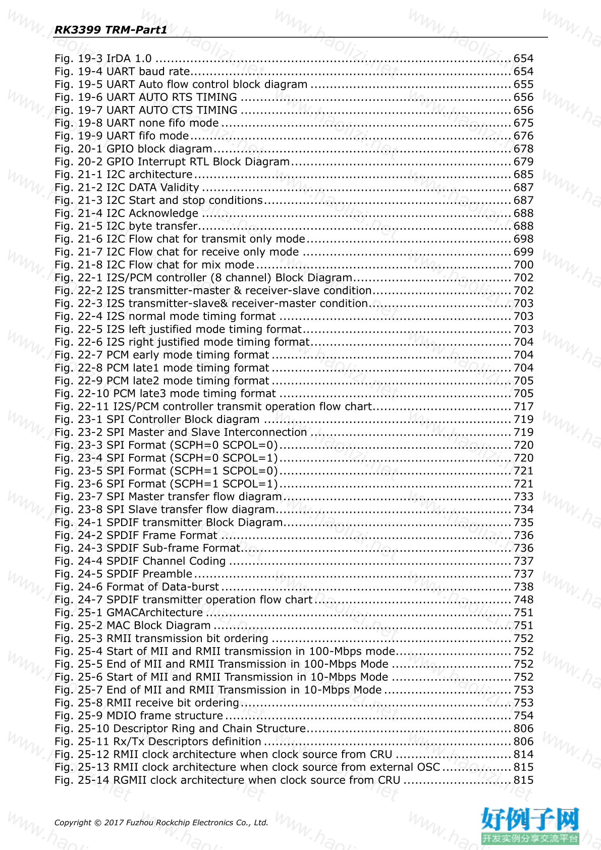
Fig. 19-3 IrDA 1.0 ............................................................................................ 654
Fig. 19-4 UART baud rate................................................................................... 654
Fig. 19-5 UART Auto flow control block diagram .................................................... 655
Fig. 19-6 UART AUTO RTS TIMING ...................................................................... 656
Fig. 19-7 UART AUTO CTS TIMING ...................................................................... 656
Fig. 19-8 UART none fifo mode ........................................................................... 675
Fig. 19-9 UART fifo mode................................................................................... 676
Fig. 20-1 GPIO block diagram............................................................................. 678
Fig. 20-2 GPIO Interrupt RTL Block Diagram......................................................... 679
Fig. 21-1 I2C architecture.................................................................................. 685
Fig. 21-2 I2C DATA Validity ................................................................................ 687
Fig. 21-3 I2C Start and stop conditions................................................................ 687
Fig. 21-4 I2C Acknowledge ................................................................................ 688
Fig. 21-5 I2C byte transfer................................................................................. 688
Fig. 21-6 I2C Flow chat for transmit only mode..................................................... 698
Fig. 21-7 I2C Flow chat for receive only mode ...................................................... 699
Fig. 21-8 I2C Flow chat for mix mode.................................................................. 700
Fig. 22-1 I2S/PCM controller (8 channel) Block Diagram......................................... 702
Fig. 22-2 I2S transmitter-master & receiver-slave condition.................................... 702
Fig. 22-3 I2S transmitter-slave& receiver-master condition..................................... 703
Fig. 22-4 I2S normal mode timing format ............................................................ 703
Fig. 22-5 I2S left justified mode timing format...................................................... 703
Fig. 22-6 I2S right justified mode timing format.................................................... 704
Fig. 22-7 PCM early mode timing format .............................................................. 704
Fig. 22-8 PCM late1 mode timing format.............................................................. 704
Fig. 22-9 PCM late2 mode timing format.............................................................. 705
Fig. 22-10 PCM late3 mode timing format ............................................................ 705
Fig. 22-11 I2S/PCM controller transmit operation flow chart.................................... 717
Fig. 23-1 SPI Controller Block diagram ................................................................ 719
Fig. 23-2 SPI Master and Slave Interconnection .................................................... 719
Fig. 23-3 SPI Format (SCPH=0 SCPOL=0)............................................................ 720
Fig. 23-4 SPI Format (SCPH=0 SCPOL=1)............................................................ 720
Fig. 23-5 SPI Format (SCPH=1 SCPOL=0)............................................................ 721
Fig. 23-6 SPI Format (SCPH=1 SCPOL=1)............................................................ 721
Fig. 23-7 SPI Master transfer flow diagram........................................................... 733
Fig. 23-8 SPI Slave transfer flow diagram............................................................. 734
Fig. 24-1 SPDIF transmitter Block Diagram........................................................... 735
Fig. 24-2 SPDIF Frame Format ........................................................................... 736
Fig. 24-3 SPDIF Sub-frame Format...................................................................... 736
Fig. 24-4 SPDIF Channel Coding ......................................................................... 737
Fig. 24-5 SPDIF Preamble.................................................................................. 737
Fig. 24-6 Format of Data-burst........................................................................... 738
Fig. 24-7 SPDIF transmitter operation flow chart................................................... 748
Fig. 25-1 GMACArchitecture ............................................................................... 751
Fig. 25-2 MAC Block Diagram ............................................................................. 751
Fig. 25-3 RMII transmission bit ordering .............................................................. 752
Fig. 25-4 Start of MII and RMII transmission in 100-Mbps mode.............................. 752
Fig. 25-5 End of MII and RMII Transmission in 100-Mbps Mode ............................... 752
Fig. 25-6 Start of MII and RMII Transmission in 10-Mbps Mode ............................... 752
Fig. 25-7 End of MII and RMII Transmission in 10-Mbps Mode ................................. 753
Fig. 25-8 RMII receive bit ordering...................................................................... 753
Fig. 25-9 MDIO frame structure .......................................................................... 754
Fig. 25-10 Descriptor Ring and Chain Structure..................................................... 806
Fig. 25-11 Rx/Tx Descriptors definition ................................................................ 806
Fig. 25-12 RMII clock architecture when clock source from CRU .............................. 814
Fig. 25-13 RMII clock architecture when clock source from external OSC.................. 815
Fig. 25-14 RGMII clock architecture when clock source from CRU ............................ 815
Copyright © 2017 Fuzhou Rockchip Electronics Co., Ltd. 9RK3399 TRM-Part1
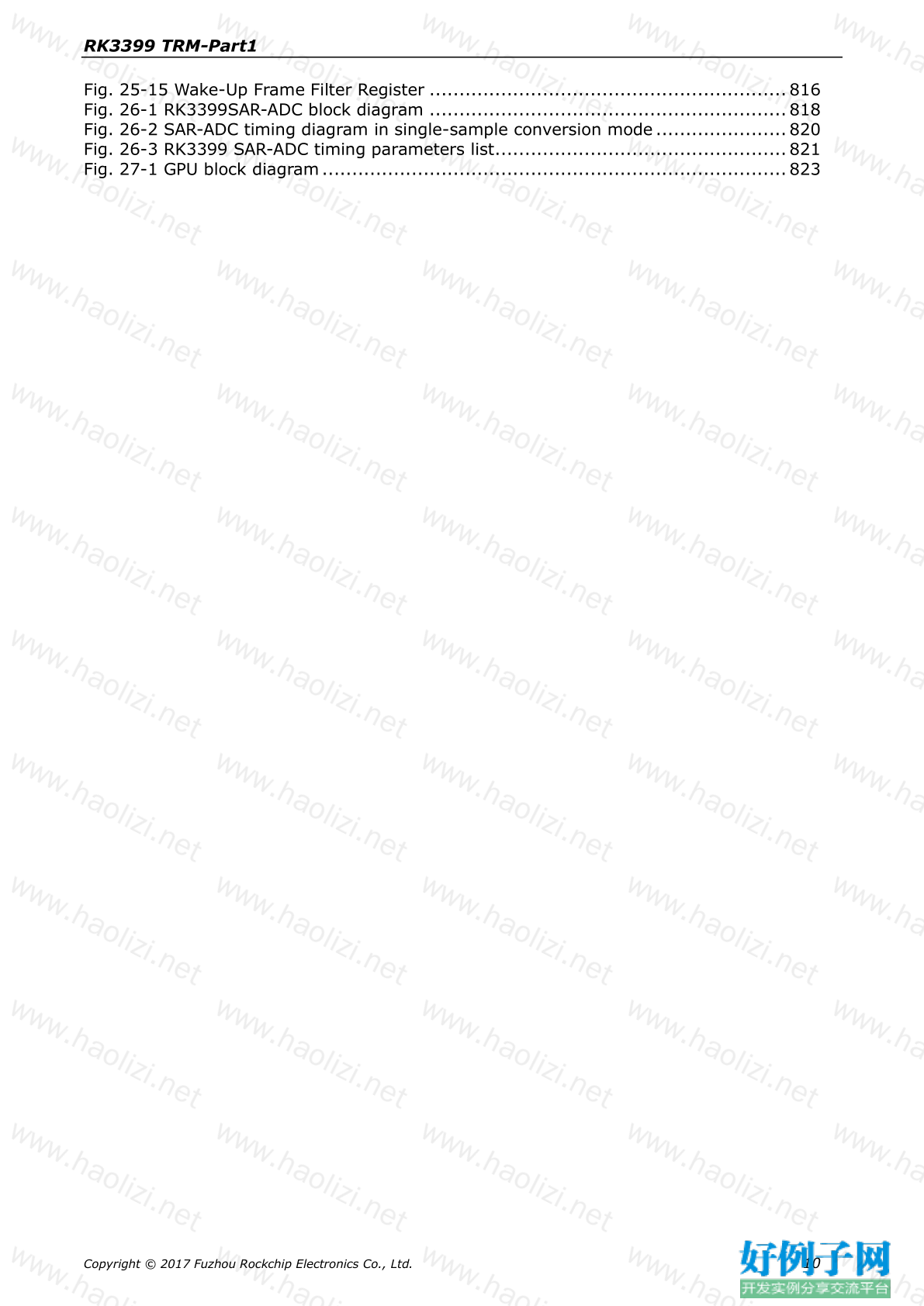
Fig. 25-15 Wake-Up Frame Filter Register ............................................................ 816
Fig. 26-1 RK3399SAR-ADC block diagram ............................................................ 818
Fig. 26-2 SAR-ADC timing diagram in single-sample conversion mode ...................... 820
Fig. 26-3 RK3399 SAR-ADC timing parameters list................................................. 821
Fig. 27-1 GPU block diagram .............................................................................. 823
Copyright © 2017 Fuzhou Rockchip Electronics Co., Ltd. 10RK3399 TRM-Part1
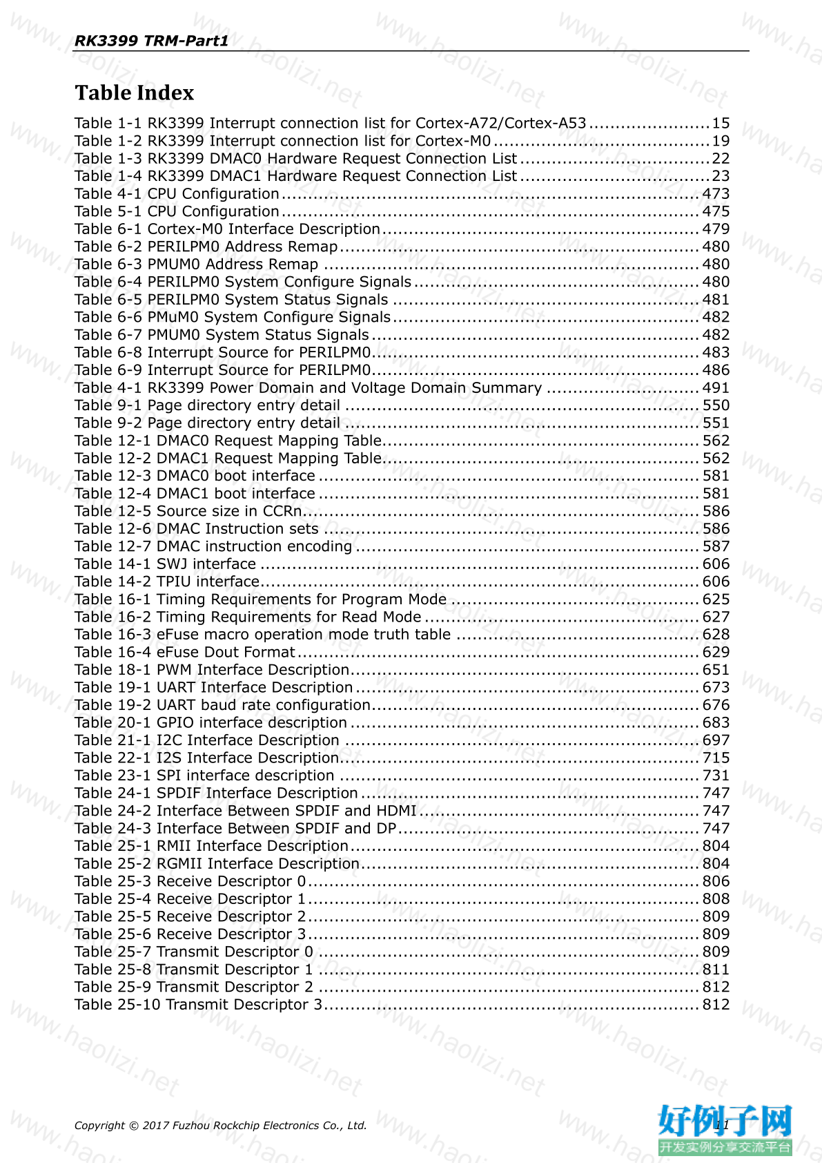
Table Index
Table 1-1 RK3399 Interrupt connection list for Cortex-A72/Cortex-A53.......................15
Table 1-2 RK3399 Interrupt connection list for Cortex-M0.........................................19
Table 1-3 RK3399 DMAC0 Hardware Request Connection List....................................22
Table 1-4 RK3399 DMAC1 Hardware Request Connection List....................................23
Table 4-1 CPU Configuration............................................................................... 473
Table 5-1 CPU Configuration............................................................................... 475
Table 6-1 Cortex-M0 Interface Description............................................................ 479
Table 6-2 PERILPM0 Address Remap.................................................................... 480
Table 6-3 PMUM0 Address Remap ....................................................................... 480
Table 6-4 PERILPM0 System Configure Signals ...................................................... 480
Table 6-5 PERILPM0 System Status Signals .......................................................... 481
Table 6-6 PMuM0 System Configure Signals.......................................................... 482
Table 6-7 PMUM0 System Status Signals .............................................................. 482
Table 6-8 Interrupt Source for PERILPM0.............................................................. 483
Table 6-9 Interrupt Source for PERILPM0.............................................................. 486
Table 4-1 RK3399 Power Domain and Voltage Domain Summary ............................. 491
Table 9-1 Page directory entry detail ................................................................... 550
Table 9-2 Page directory entry detail ................................................................... 551
Table 12-1 DMAC0 Request Mapping Table............................................................ 562
Table 12-2 DMAC1 Request Mapping Table............................................................ 562
Table 12-3 DMAC0 boot interface ........................................................................ 581
Table 12-4 DMAC1 boot interface ........................................................................ 581
Table 12-5 Source size in CCRn........................................................................... 586
Table 12-6 DMAC Instruction sets ....................................................................... 586
Table 12-7 DMAC instruction encoding ................................................................. 587
Table 14-1 SWJ interface ................................................................................... 606
Table 14-2 TPIU interface................................................................................... 606
Table 16-1 Timing Requirements for Program Mode ............................................... 625
Table 16-2 Timing Requirements for Read Mode .................................................... 627
Table 16-3 eFuse macro operation mode truth table .............................................. 628
Table 16-4 eFuse Dout Format............................................................................ 629
Table 18-1 PWM Interface Description.................................................................. 651
Table 19-1 UART Interface Description................................................................. 673
Table 19-2 UART baud rate configuration.............................................................. 676
Table 20-1 GPIO interface description .................................................................. 683
Table 21-1 I2C Interface Description ................................................................... 697
Table 22-1 I2S Interface Description.................................................................... 715
Table 23-1 SPI interface description .................................................................... 731
Table 24-1 SPDIF Interface Description................................................................ 747
Table 24-2 Interface Between SPDIF and HDMI ..................................................... 747
Table 24-3 Interface Between SPDIF and DP......................................................... 747
Table 25-1 RMII Interface Description.................................................................. 804
Table 25-2 RGMII Interface Description................................................................ 804
Table 25-3 Receive Descriptor 0.......................................................................... 806
Table 25-4 Receive Descriptor 1.......................................................................... 808
Table 25-5 Receive Descriptor 2.......................................................................... 809
Table 25-6 Receive Descriptor 3.......................................................................... 809
Table 25-7 Transmit Descriptor 0 ........................................................................ 809
Table 25-8 Transmit Descriptor 1 ........................................................................ 811
Table 25-9 Transmit Descriptor 2 ........................................................................ 812
Table 25-10 Transmit Descriptor 3....................................................................... 812


网友评论
我要评论