实例介绍
【实例截图】

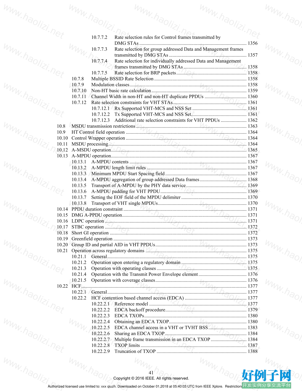
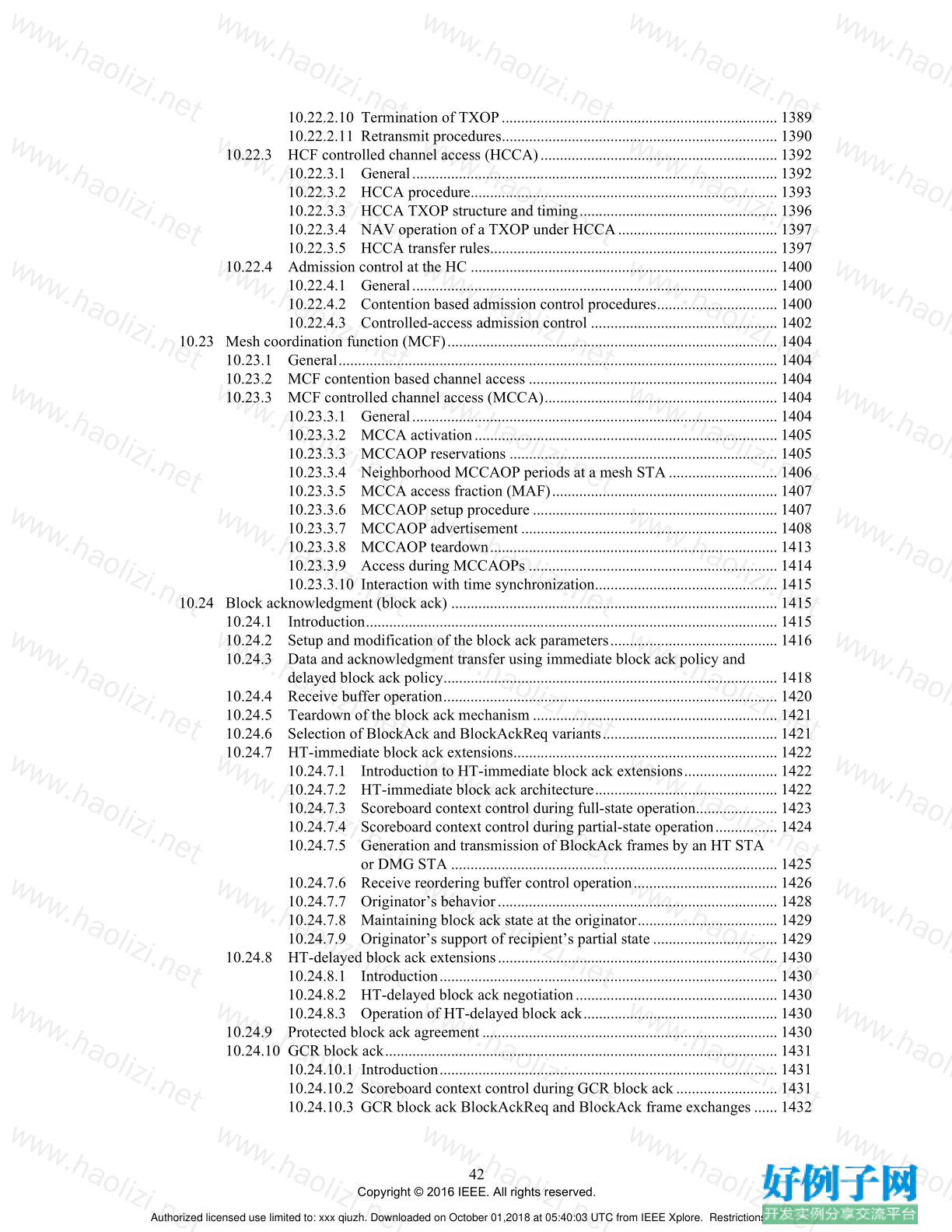
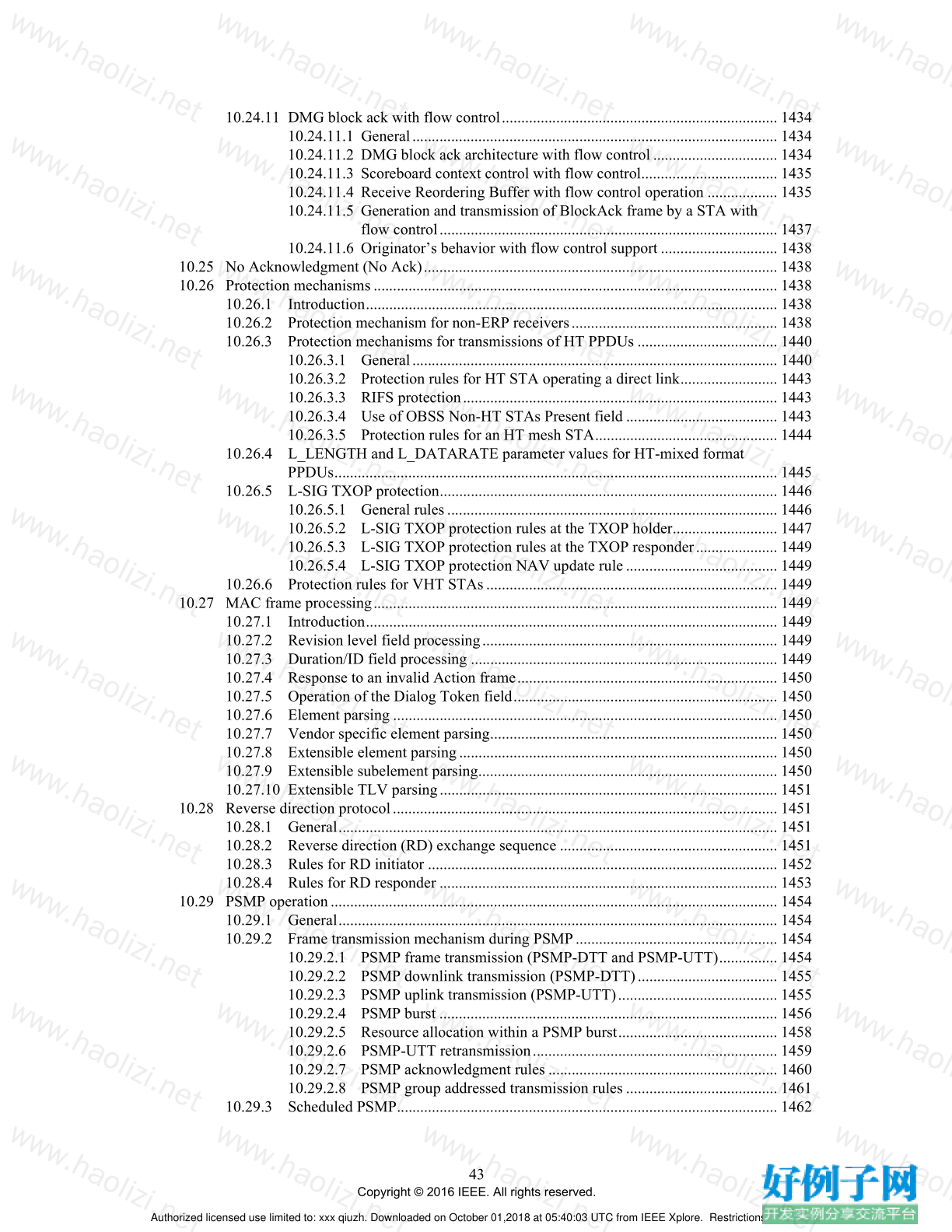
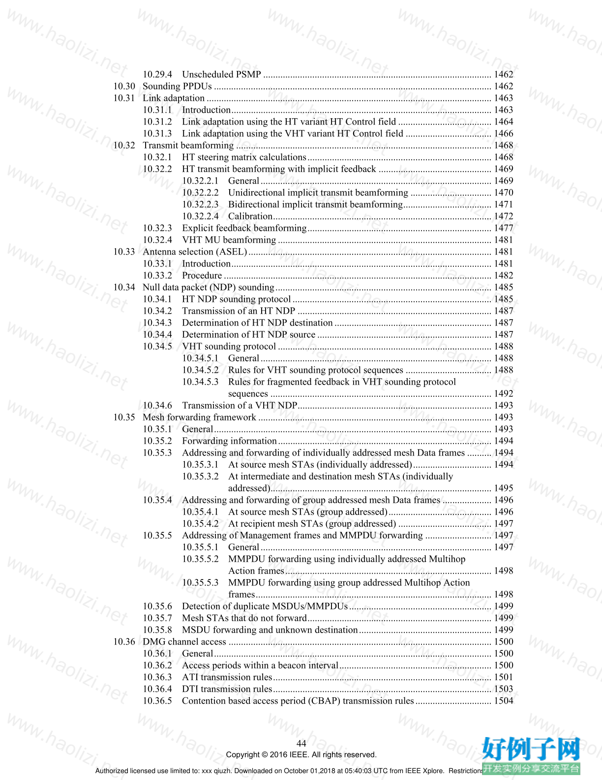




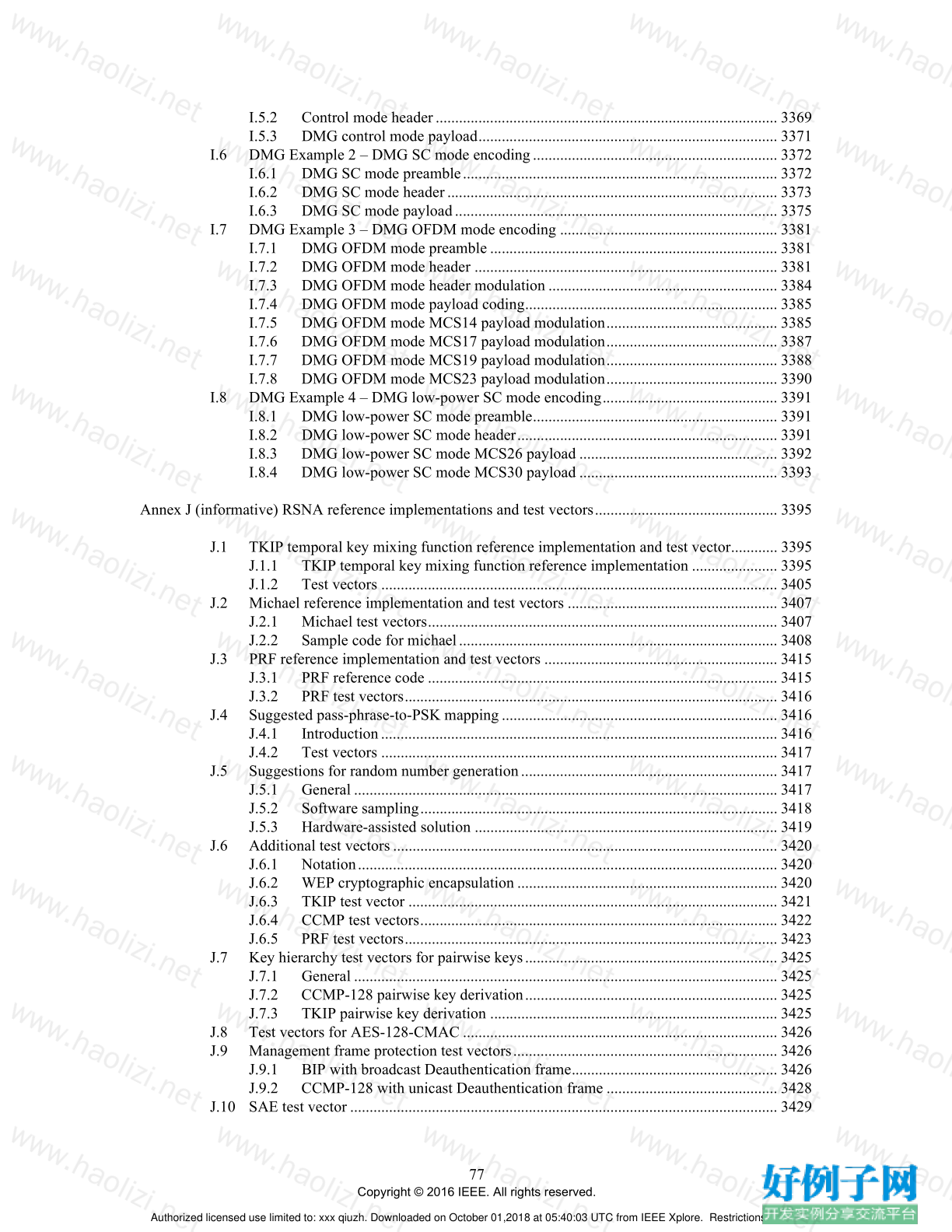
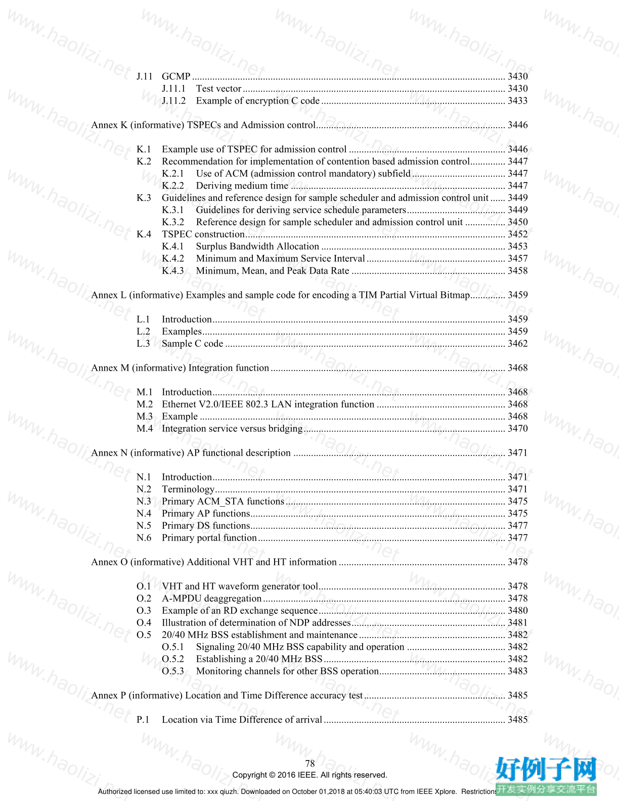
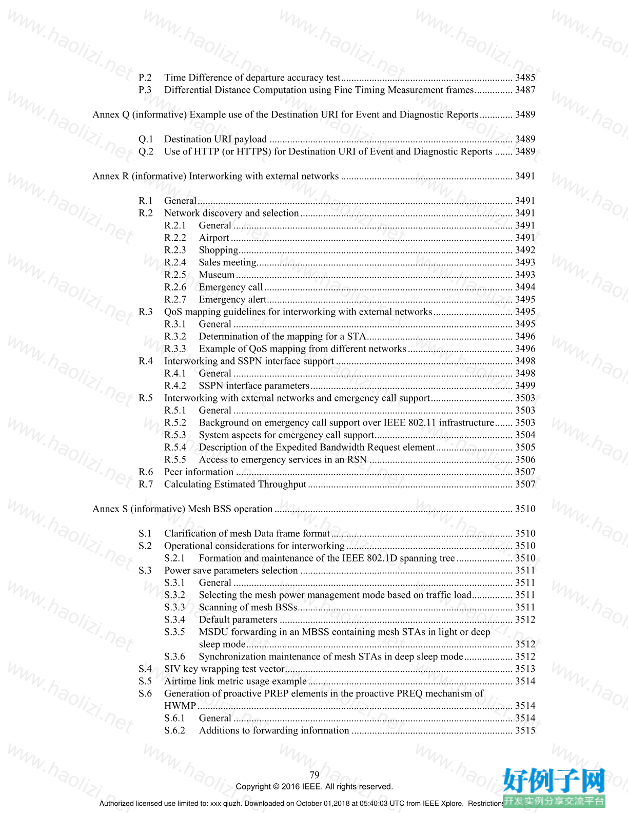
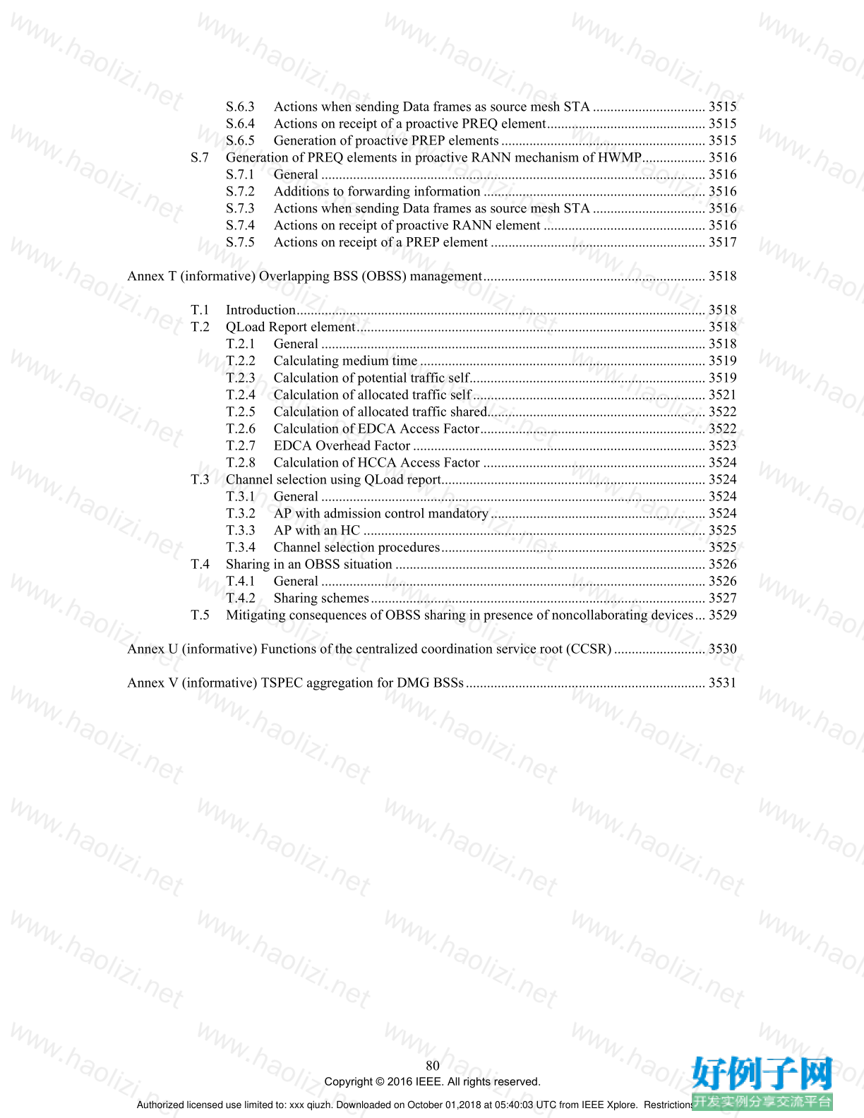




【核心代码】
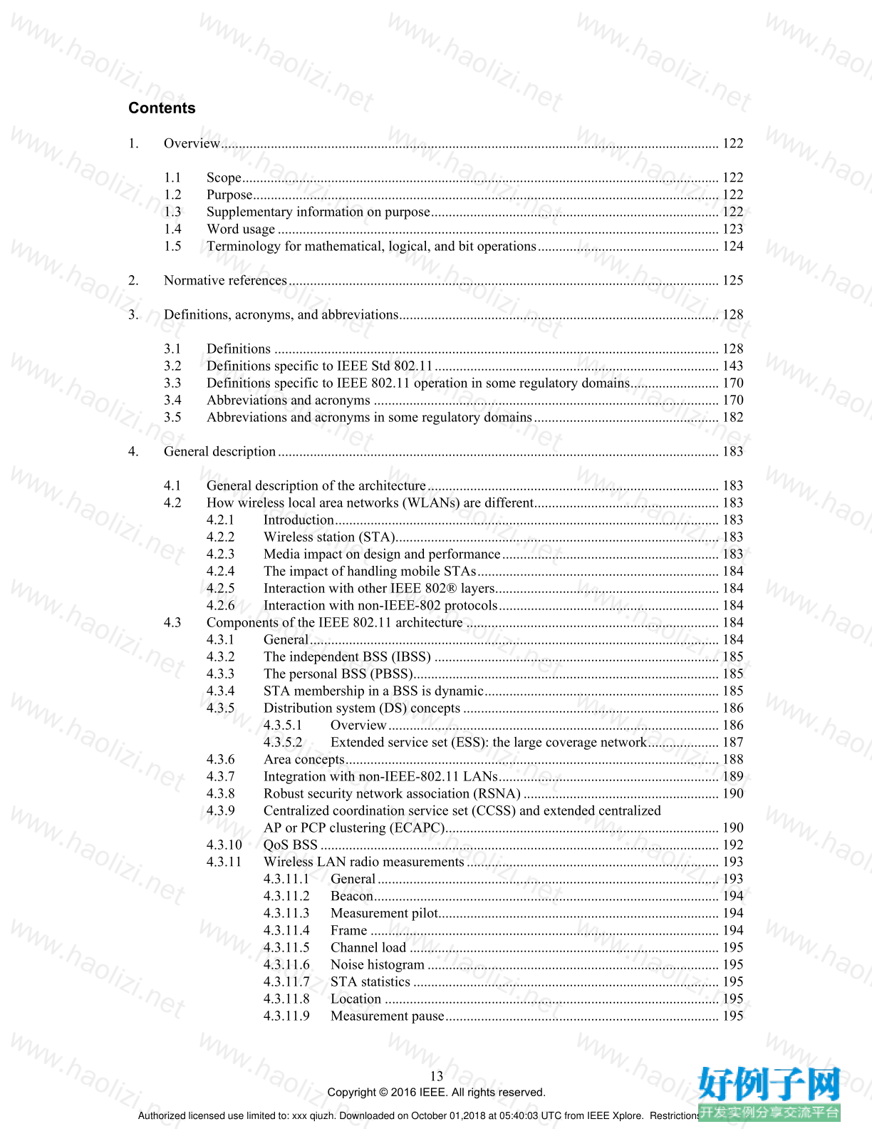
Contents
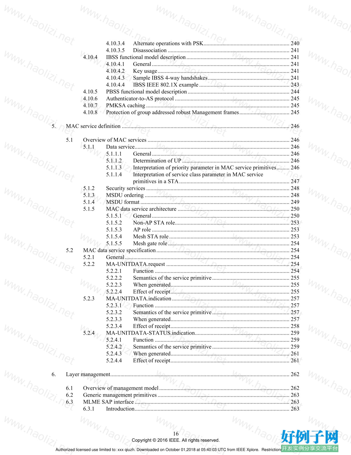
1. Overview............................................................................................................................................ 122
1.1 Scope...................................................................................................................................... 122
1.2 Purpose................................................................................................................................... 122
1.3 Supplementary information on purpose................................................................................. 122
1.4 Word usage............................................................................................................................ 123
1.5 Terminology for mathematical, logical, and bit operations................................................... 124
2. Normative references......................................................................................................................... 125
3. Definitions, acronyms, and abbreviations.......................................................................................... 128
3.1 Definitions ............................................................................................................................. 128
3.2 Definitions specific to IEEE Std 802.11................................................................................ 143
3.3 Definitions specific to IEEE 802.11 operation in some regulatory domains......................... 170
3.4 Abbreviations and acronyms ................................................................................................. 170
3.5 Abbreviations and acronyms in some regulatory domains.................................................... 182
4. General description............................................................................................................................ 183
4.1 General description of the architecture.................................................................................. 183
4.2 How wireless local area networks (WLANs) are different.................................................... 183
4.2.1 Introduction............................................................................................................ 183
4.2.2 Wireless station (STA)........................................................................................... 183
4.2.3 Media impact on design and performance............................................................. 183
4.2.4 The impact of handling mobile STAs.................................................................... 184
4.2.5 Interaction with other IEEE 802® layers............................................................... 184
4.2.6 Interaction with non-IEEE-802 protocols.............................................................. 184
4.3 Components of the IEEE 802.11 architecture ....................................................................... 184
4.3.1 General................................................................................................................... 184
4.3.2 The independent BSS (IBSS) ................................................................................ 185
4.3.3 The personal BSS (PBSS)...................................................................................... 185
4.3.4 STA membership in a BSS is dynamic.................................................................. 185
4.3.5 Distribution system (DS) concepts........................................................................ 186
4.3.5.1 Overview............................................................................................. 186
4.3.5.2 Extended service set (ESS): the large coverage network.................... 187
4.3.6 Area concepts......................................................................................................... 188
4.3.7 Integration with non-IEEE-802.11 LANs.............................................................. 189
4.3.8 Robust security network association (RSNA)....................................................... 190
4.3.9 Centralized coordination service set (CCSS) and extended centralized
AP or PCP clustering (ECAPC)............................................................................. 190
4.3.10 QoS BSS................................................................................................................ 192
4.3.11 Wireless LAN radio measurements....................................................................... 193
4.3.11.1 General................................................................................................ 193
4.3.11.2 Beacon................................................................................................. 194
4.3.11.3 Measurement pilot............................................................................... 194
4.3.11.4 Frame .................................................................................................. 194
4.3.11.5 Channel load ....................................................................................... 195
4.3.11.6 Noise histogram .................................................................................. 195
4.3.11.7 STA statistics ...................................................................................... 195
4.3.11.8 Location .............................................................................................. 195
4.3.11.9 Measurement pause............................................................................. 195
Authorized licensed use limited to: xxx qiuzh. Downloaded on October 01,2018 at 05:40:03 UTC from IEEE Xplore. Restrictions apply.
14
Copyright © 2016 IEEE. All rights reserved.
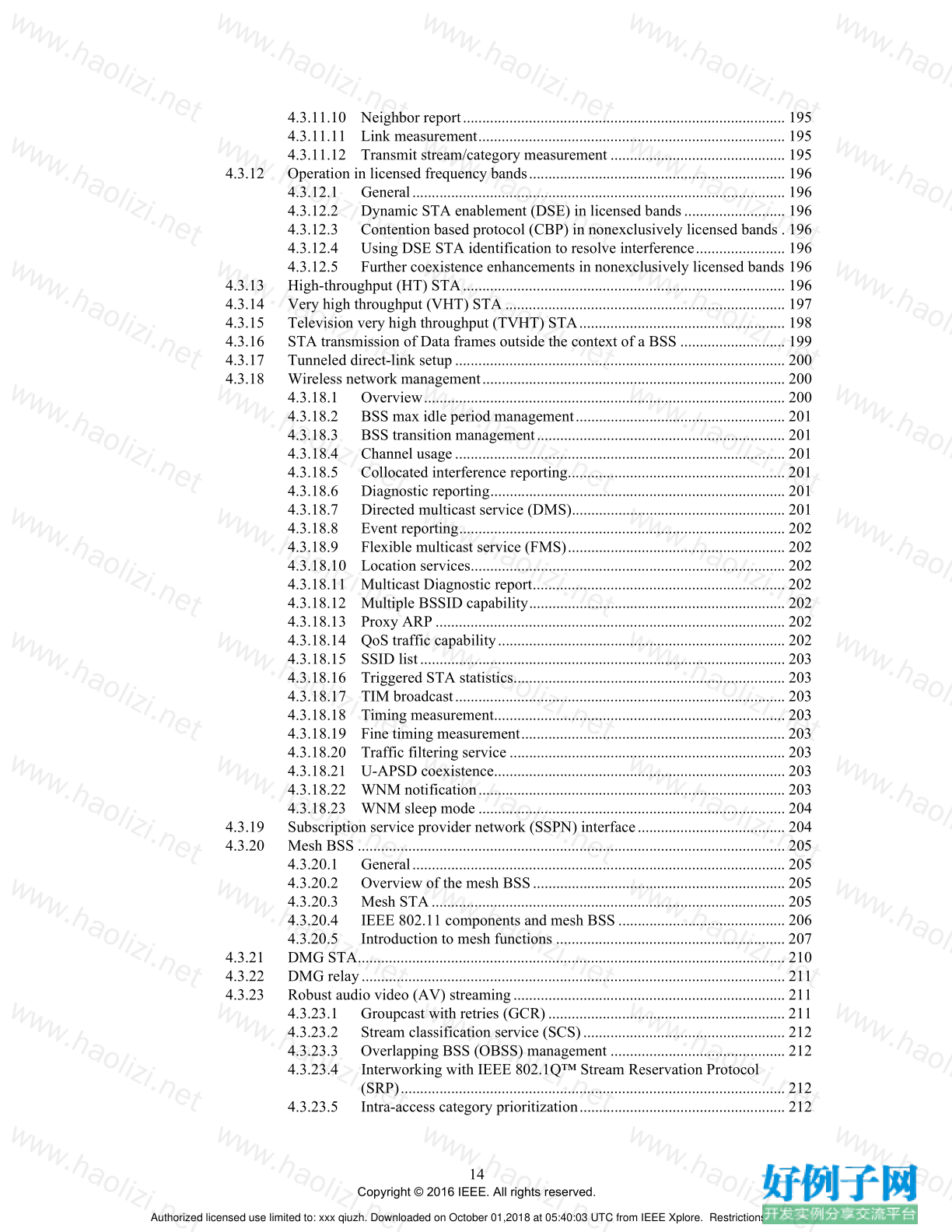
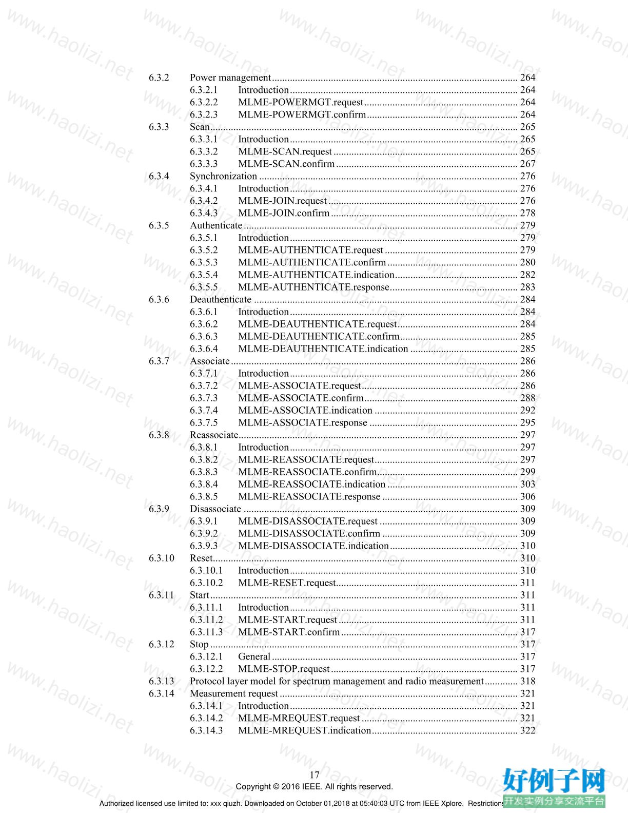
4.3.11.10 Neighbor report................................................................................... 195
4.3.11.11 Link measurement............................................................................... 195
4.3.11.12 Transmit stream/category measurement ............................................. 195
4.3.12 Operation in licensed frequency bands.................................................................. 196
4.3.12.1 General................................................................................................ 196
4.3.12.2 Dynamic STA enablement (DSE) in licensed bands.......................... 196
4.3.12.3 Contention based protocol (CBP) in nonexclusively licensed bands . 196
4.3.12.4 Using DSE STA identification to resolve interference....................... 196
4.3.12.5 Further coexistence enhancements in nonexclusively licensed bands 196
4.3.13 High-throughput (HT) STA................................................................................... 196
4.3.14 Very high throughput (VHT) STA ........................................................................ 197
4.3.15 Television very high throughput (TVHT) STA..................................................... 198
4.3.16 STA transmission of Data frames outside the context of a BSS ........................... 199
4.3.17 Tunneled direct-link setup..................................................................................... 200
4.3.18 Wireless network management.............................................................................. 200
4.3.18.1 Overview............................................................................................. 200
4.3.18.2 BSS max idle period management...................................................... 201
4.3.18.3 BSS transition management................................................................ 201
4.3.18.4 Channel usage..................................................................................... 201
4.3.18.5 Collocated interference reporting........................................................ 201
4.3.18.6 Diagnostic reporting............................................................................ 201
4.3.18.7 Directed multicast service (DMS)....................................................... 201
4.3.18.8 Event reporting.................................................................................... 202
4.3.18.9 Flexible multicast service (FMS)........................................................ 202
4.3.18.10 Location services................................................................................. 202
4.3.18.11 Multicast Diagnostic report................................................................. 202
4.3.18.12 Multiple BSSID capability.................................................................. 202
4.3.18.13 Proxy ARP .......................................................................................... 202
4.3.18.14 QoS traffic capability.......................................................................... 202
4.3.18.15 SSID list.............................................................................................. 203
4.3.18.16 Triggered STA statistics...................................................................... 203
4.3.18.17 TIM broadcast..................................................................................... 203
4.3.18.18 Timing measurement........................................................................... 203
4.3.18.19 Fine timing measurement.................................................................... 203
4.3.18.20 Traffic filtering service ....................................................................... 203
4.3.18.21 U-APSD coexistence........................................................................... 203
4.3.18.22 WNM notification............................................................................... 203
4.3.18.23 WNM sleep mode ............................................................................... 204
4.3.19 Subscription service provider network (SSPN) interface...................................... 204
4.3.20 Mesh BSS .............................................................................................................. 205
4.3.20.1 General................................................................................................ 205
4.3.20.2 Overview of the mesh BSS................................................................. 205
4.3.20.3 Mesh STA........................................................................................... 205
4.3.20.4 IEEE 802.11 components and mesh BSS ........................................... 206
4.3.20.5 Introduction to mesh functions ........................................................... 207
4.3.21 DMG STA.............................................................................................................. 210
4.3.22 DMG relay............................................................................................................. 211
4.3.23 Robust audio video (AV) streaming...................................................................... 211
4.3.23.1 Groupcast with retries (GCR)............................................................. 211
4.3.23.2 Stream classification service (SCS).................................................... 212
4.3.23.3 Overlapping BSS (OBSS) management ............................................. 212
4.3.23.4 Interworking with IEEE 802.1Q™ Stream Reservation Protocol
(SRP)................................................................................................... 212
4.3.23.5 Intra-access category prioritization..................................................... 212
Authorized licensed use limited to: xxx qiuzh. Downloaded on October 01,2018 at 05:40:03 UTC from IEEE Xplore. Restrictions apply.
15
Copyright © 2016 IEEE. All rights reserved.
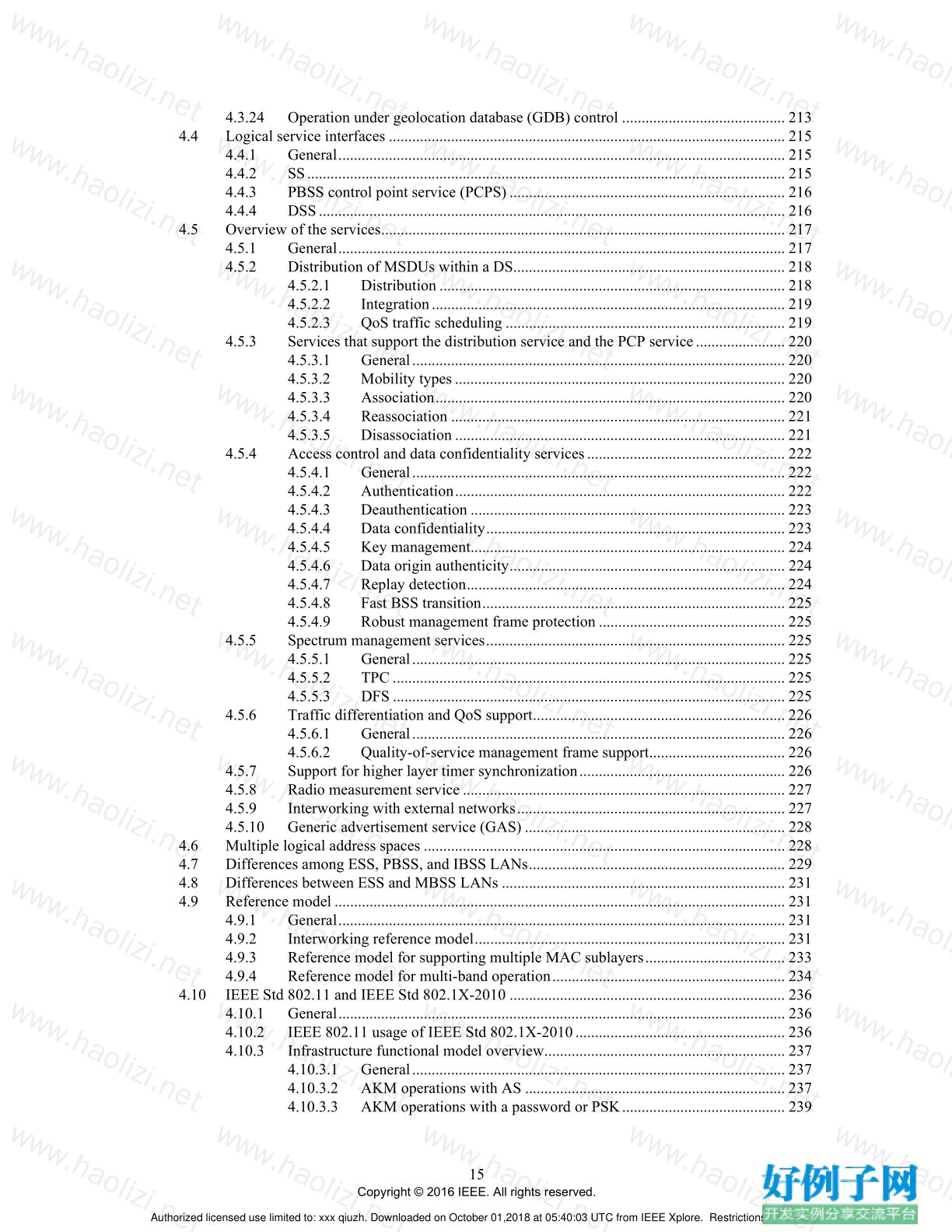
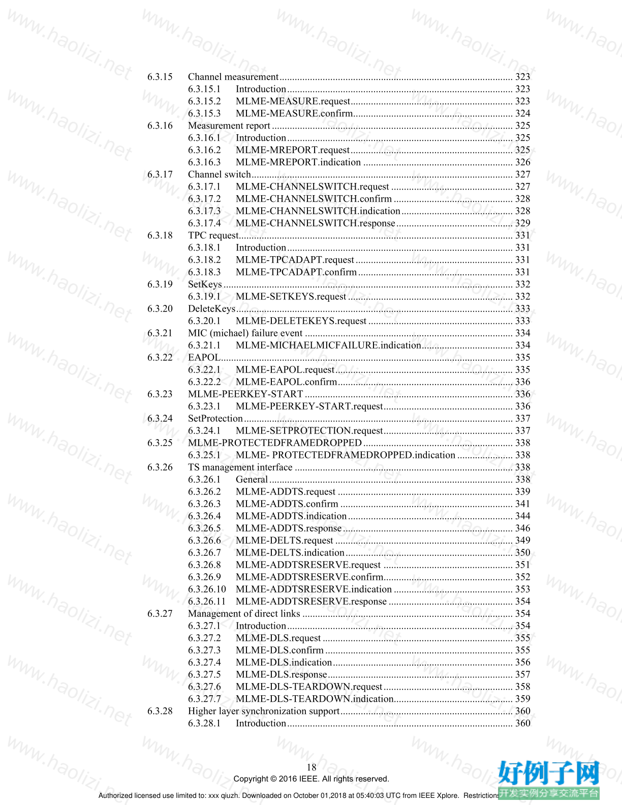
4.3.24 Operation under geolocation database (GDB) control .......................................... 213
4.4 Logical service interfaces ...................................................................................................... 215
4.4.1 General................................................................................................................... 215
4.4.2 SS........................................................................................................................... 215
4.4.3 PBSS control point service (PCPS)....................................................................... 216
4.4.4 DSS........................................................................................................................ 216
4.5 Overview of the services........................................................................................................ 217
4.5.1 General................................................................................................................... 217
4.5.2 Distribution of MSDUs within a DS...................................................................... 218
4.5.2.1 Distribution ......................................................................................... 218
4.5.2.2 Integration........................................................................................... 219
4.5.2.3 QoS traffic scheduling ........................................................................ 219
4.5.3 Services that support the distribution service and the PCP service....................... 220
4.5.3.1 General................................................................................................ 220
4.5.3.2 Mobility types..................................................................................... 220
4.5.3.3 Association.......................................................................................... 220
4.5.3.4 Reassociation ...................................................................................... 221
4.5.3.5 Disassociation ..................................................................................... 221
4.5.4 Access control and data confidentiality services................................................... 222
4.5.4.1 General................................................................................................ 222
4.5.4.2 Authentication..................................................................................... 222
4.5.4.3 Deauthentication ................................................................................. 223
4.5.4.4 Data confidentiality............................................................................. 223
4.5.4.5 Key management................................................................................. 224
4.5.4.6 Data origin authenticity....................................................................... 224
4.5.4.7 Replay detection.................................................................................. 224
4.5.4.8 Fast BSS transition.............................................................................. 225
4.5.4.9 Robust management frame protection ................................................ 225
4.5.5 Spectrum management services............................................................................. 225
4.5.5.1 General................................................................................................ 225
4.5.5.2 TPC ..................................................................................................... 225
4.5.5.3 DFS ..................................................................................................... 225
4.5.6 Traffic differentiation and QoS support................................................................. 226
4.5.6.1 General................................................................................................ 226
4.5.6.2 Quality-of-service management frame support................................... 226
4.5.7 Support for higher layer timer synchronization..................................................... 226
4.5.8 Radio measurement service................................................................................... 227
4.5.9 Interworking with external networks..................................................................... 227
4.5.10 Generic advertisement service (GAS) ................................................................... 228
4.6 Multiple logical address spaces ............................................................................................. 228
4.7 Differences among ESS, PBSS, and IBSS LANs.................................................................. 229
4.8 Differences between ESS and MBSS LANs ......................................................................... 231
4.9 Reference model.................................................................................................................... 231
4.9.1 General................................................................................................................... 231
4.9.2 Interworking reference model................................................................................ 231
4.9.3 Reference model for supporting multiple MAC sublayers.................................... 233
4.9.4 Reference model for multi-band operation............................................................ 234
4.10 IEEE Std 802.11 and IEEE Std 802.1X-2010 ....................................................................... 236
4.10.1 General................................................................................................................... 236
4.10.2 IEEE 802.11 usage of IEEE Std 802.1X-2010...................................................... 236
4.10.3 Infrastructure functional model overview.............................................................. 237
4.10.3.1 General................................................................................................ 237
4.10.3.2 AKM operations with AS ................................................................... 237
4.10.3.3 AKM operations with a password or PSK.......................................... 239
Authorized licensed use limited to: xxx qiuzh. Downloaded on October 01,2018 at 05:40:03 UTC from IEEE Xplore. Restrictions apply.
16
Copyright © 2016 IEEE. All rights reserved.
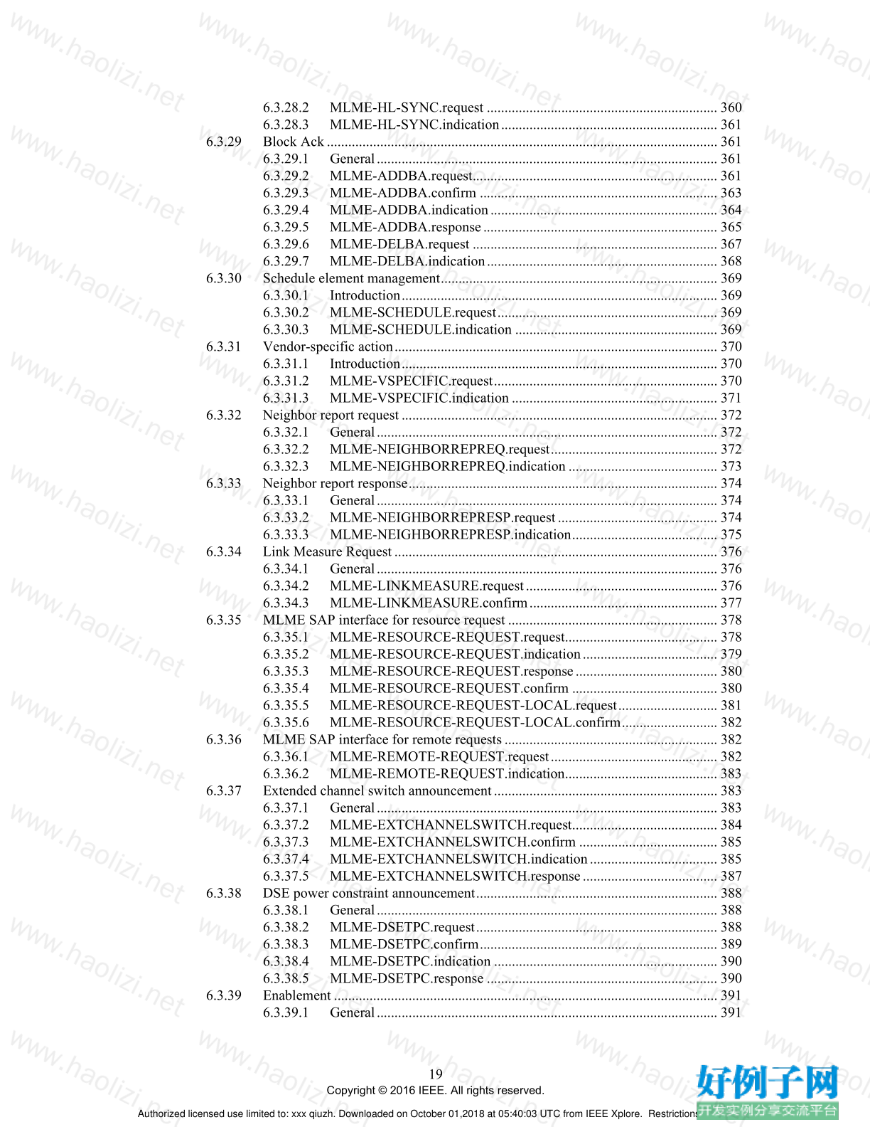
4.10.3.4 Alternate operations with PSK............................................................ 240
4.10.3.5 Disassociation ..................................................................................... 241
4.10.4 IBSS functional model description........................................................................ 241
4.10.4.1 General................................................................................................ 241
4.10.4.2 Key usage............................................................................................ 241
4.10.4.3 Sample IBSS 4-way handshakes......................................................... 241
4.10.4.4 IBSS IEEE 802.1X example............................................................... 243
4.10.5 PBSS functional model description....................................................................... 244
4.10.6 Authenticator-to-AS protocol................................................................................ 245
4.10.7 PMKSA caching.................................................................................................... 245
4.10.8 Protection of group addressed robust Management frames................................... 245
5. MAC service definition ..................................................................................................................... 246
5.1 Overview of MAC services ................................................................................................... 246
5.1.1 Data service............................................................................................................ 246
5.1.1.1 General................................................................................................ 246
5.1.1.2 Determination of UP........................................................................... 246
5.1.1.3 Interpretation of priority parameter in MAC service primitives......... 246
5.1.1.4 Interpretation of service class parameter in MAC service
primitives in a STA............................................................................. 247
5.1.2 Security services.................................................................................................... 248
5.1.3 MSDU ordering ..................................................................................................... 248
5.1.4 MSDU format........................................................................................................ 249
5.1.5 MAC data service architecture .............................................................................. 250
5.1.5.1 General................................................................................................ 250
5.1.5.2 Non-AP STA role................................................................................ 253
5.1.5.3 AP role ................................................................................................ 253
5.1.5.4 Mesh STA role.................................................................................... 253
5.1.5.5 Mesh gate role..................................................................................... 254
5.2 MAC data service specification............................................................................................. 254
5.2.1 General................................................................................................................... 254
5.2.2 MA-UNITDATA.request ...................................................................................... 254
5.2.2.1 Function .............................................................................................. 254
5.2.2.2 Semantics of the service primitive...................................................... 255
5.2.2.3 When generated................................................................................... 255
5.2.2.4 Effect of receipt................................................................................... 255
5.2.3 MA-UNITDATA.indication.................................................................................. 257
5.2.3.1 Function .............................................................................................. 257
5.2.3.2 Semantics of the service primitive...................................................... 257
5.2.3.3 When generated................................................................................... 257
5.2.3.4 Effect of receipt................................................................................... 258
5.2.4 MA-UNITDATA-STATUS.indication.................................................................. 259
5.2.4.1 Function .............................................................................................. 259
5.2.4.2 Semantics of the service primitive...................................................... 259
5.2.4.3 When generated................................................................................... 261
5.2.4.4 Effect of receipt................................................................................... 261
6. Layer management............................................................................................................................. 262
6.1 Overview of management model........................................................................................... 262
6.2 Generic management primitives............................................................................................ 263
6.3 MLME SAP interface............................................................................................................ 263
6.3.1 Introduction............................................................................................................ 263
Authorized licensed use limited to: xxx qiuzh. Downloaded on October 01,2018 at 05:40:03 UTC from IEEE Xplore. Restrictions apply.
17
Copyright © 2016 IEEE. All rights reserved.
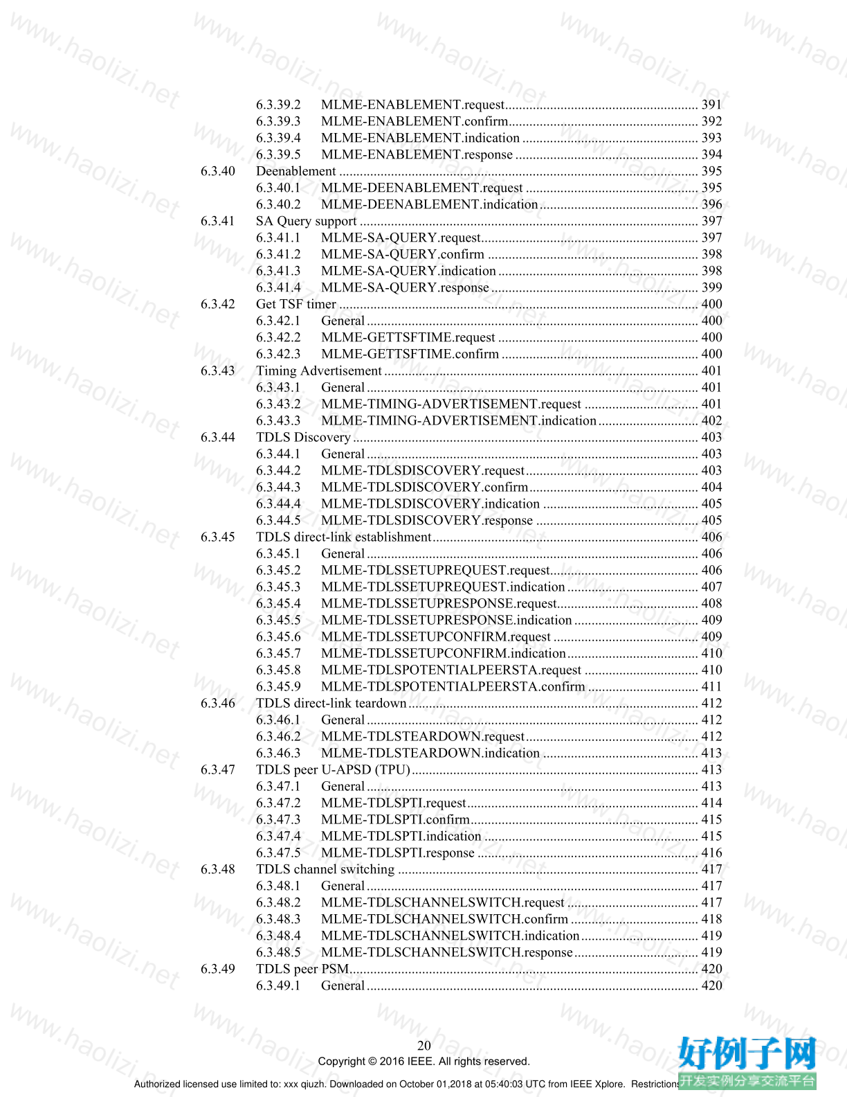
6.3.2 Power management................................................................................................ 264
6.3.2.1 Introduction......................................................................................... 264
6.3.2.2 MLME-POWERMGT.request............................................................ 264
6.3.2.3 MLME-POWERMGT.confirm........................................................... 264
6.3.3 Scan........................................................................................................................ 265
6.3.3.1 Introduction......................................................................................... 265
6.3.3.2 MLME-SCAN.request........................................................................ 265
6.3.3.3 MLME-SCAN.confirm....................................................................... 267
6.3.4 Synchronization..................................................................................................... 276
6.3.4.1 Introduction......................................................................................... 276
6.3.4.2 MLME-JOIN.request.......................................................................... 276
6.3.4.3 MLME-JOIN.confirm......................................................................... 278
6.3.5 Authenticate........................................................................................................... 279
6.3.5.1 Introduction......................................................................................... 279
6.3.5.2 MLME-AUTHENTICATE.request.................................................... 279
6.3.5.3 MLME-AUTHENTICATE.confirm................................................... 280
6.3.5.4 MLME-AUTHENTICATE.indication................................................ 282
6.3.5.5 MLME-AUTHENTICATE.response.................................................. 283
6.3.6 Deauthenticate ....................................................................................................... 284
6.3.6.1 Introduction......................................................................................... 284
6.3.6.2 MLME-DEAUTHENTICATE.request............................................... 284
6.3.6.3 MLME-DEAUTHENTICATE.confirm.............................................. 285
6.3.6.4 MLME-DEAUTHENTICATE.indication .......................................... 285
6.3.7 Associate................................................................................................................ 286
6.3.7.1 Introduction......................................................................................... 286
6.3.7.2 MLME-ASSOCIATE.request............................................................. 286
6.3.7.3 MLME-ASSOCIATE.confirm............................................................ 288
6.3.7.4 MLME-ASSOCIATE.indication ........................................................ 292
6.3.7.5 MLME-ASSOCIATE.response .......................................................... 295
6.3.8 Reassociate............................................................................................................. 297
6.3.8.1 Introduction......................................................................................... 297
6.3.8.2 MLME-REASSOCIATE.request........................................................ 297
6.3.8.3 MLME-REASSOCIATE.confirm....................................................... 299
6.3.8.4 MLME-REASSOCIATE.indication................................................... 303
6.3.8.5 MLME-REASSOCIATE.response..................................................... 306
6.3.9 Disassociate ........................................................................................................... 309
6.3.9.1 MLME-DISASSOCIATE.request ...................................................... 309
6.3.9.2 MLME-DISASSOCIATE.confirm..................................................... 309
6.3.9.3 MLME-DISASSOCIATE.indication.................................................. 310
6.3.10 Reset....................................................................................................................... 310
6.3.10.1 Introduction......................................................................................... 310
6.3.10.2 MLME-RESET.request....................................................................... 311
6.3.11 Start........................................................................................................................ 311
6.3.11.1 Introduction......................................................................................... 311
6.3.11.2 MLME-START.request...................................................................... 311
6.3.11.3 MLME-START.confirm..................................................................... 317
6.3.12 Stop........................................................................................................................ 317
6.3.12.1 General................................................................................................ 317
6.3.12.2 MLME-STOP.request......................................................................... 317
6.3.13 Protocol layer model for spectrum management and radio measurement............. 318
6.3.14 Measurement request............................................................................................. 321
6.3.14.1 Introduction......................................................................................... 321
6.3.14.2 MLME-MREQUEST.request............................................................. 321
6.3.14.3 MLME-MREQUEST.indication......................................................... 322
Authorized licensed use limited to: xxx qiuzh. Downloaded on October 01,2018 at 05:40:03 UTC from IEEE Xplore. Restrictions apply.
18
Copyright © 2016 IEEE. All rights reserved.
6.3.15 Channel measurement............................................................................................ 323
6.3.15.1 Introduction......................................................................................... 323
6.3.15.2 MLME-MEASURE.request................................................................ 323
6.3.15.3 MLME-MEASURE.confirm............................................................... 324
6.3.16 Measurement report............................................................................................... 325
6.3.16.1 Introduction......................................................................................... 325
6.3.16.2 MLME-MREPORT.request................................................................ 325
6.3.16.3 MLME-MREPORT.indication ........................................................... 326
6.3.17 Channel switch....................................................................................................... 327
6.3.17.1 MLME-CHANNELSWITCH.request ................................................ 327
6.3.17.2 MLME-CHANNELSWITCH.confirm............................................... 328
6.3.17.3 MLME-CHANNELSWITCH.indication............................................ 328
6.3.17.4 MLME-CHANNELSWITCH.response.............................................. 329
6.3.18 TPC request............................................................................................................ 331
6.3.18.1 Introduction......................................................................................... 331
6.3.18.2 MLME-TPCADAPT.request.............................................................. 331
6.3.18.3 MLME-TPCADAPT.confirm............................................................. 331
6.3.19 SetKeys.................................................................................................................. 332
6.3.19.1 MLME-SETKEYS.request................................................................. 332
6.3.20 DeleteKeys............................................................................................................. 333
6.3.20.1 MLME-DELETEKEYS.request......................................................... 333
6.3.21 MIC (michael) failure event .................................................................................. 334
6.3.21.1 MLME-MICHAELMICFAILURE.indication.................................... 334
6.3.22 EAPOL................................................................................................................... 335
6.3.22.1 MLME-EAPOL.request...................................................................... 335
6.3.22.2 MLME-EAPOL.confirm..................................................................... 336
6.3.23 MLME-PEERKEY-START.................................................................................. 336
6.3.23.1 MLME-PEERKEY-START.request................................................... 336
6.3.24 SetProtection.......................................................................................................... 337
6.3.24.1 MLME-SETPROTECTION.request................................................... 337
6.3.25 MLME-PROTECTEDFRAMEDROPPED........................................................... 338
6.3.25.1 MLME- PROTECTEDFRAMEDROPPED.indication...................... 338
6.3.26 TS management interface ...................................................................................... 338
6.3.26.1 General................................................................................................ 338
6.3.26.2 MLME-ADDTS.request ..................................................................... 339
6.3.26.3 MLME-ADDTS.confirm .................................................................... 341
6.3.26.4 MLME-ADDTS.indication................................................................. 344
6.3.26.5 MLME-ADDTS.response................................................................... 346
6.3.26.6 MLME-DELTS.request ...................................................................... 349
6.3.26.7 MLME-DELTS.indication.................................................................. 350
6.3.26.8 MLME-ADDTSRESERVE.request ................................................... 351
6.3.26.9 MLME-ADDTSRESERVE.confirm................................................... 352
6.3.26.10 MLME-ADDTSRESERVE.indication............................................... 353
6.3.26.11 MLME-ADDTSRESERVE.response................................................. 354
6.3.27 Management of direct links ................................................................................... 354
6.3.27.1 Introduction......................................................................................... 354
6.3.27.2 MLME-DLS.request........................................................................... 355
6.3.27.3 MLME-DLS.confirm.......................................................................... 355
6.3.27.4 MLME-DLS.indication....................................................................... 356
6.3.27.5 MLME-DLS.response......................................................................... 357
6.3.27.6 MLME-DLS-TEARDOWN.request................................................... 358
6.3.27.7 MLME-DLS-TEARDOWN.indication............................................... 359
6.3.28 Higher layer synchronization support.................................................................... 360
6.3.28.1 Introduction......................................................................................... 360
Authorized licensed use limited to: xxx qiuzh. Downloaded on October 01,2018 at 05:40:03 UTC from IEEE Xplore. Restrictions apply.
19
Copyright © 2016 IEEE. All rights reserved.
6.3.28.2 MLME-HL-SYNC.request ................................................................. 360
6.3.28.3 MLME-HL-SYNC.indication............................................................. 361
6.3.29 Block Ack.............................................................................................................. 361
6.3.29.1 General................................................................................................ 361
6.3.29.2 MLME-ADDBA.request..................................................................... 361
6.3.29.3 MLME-ADDBA.confirm ................................................................... 363
6.3.29.4 MLME-ADDBA.indication................................................................ 364
6.3.29.5 MLME-ADDBA.response.................................................................. 365
6.3.29.6 MLME-DELBA.request ..................................................................... 367
6.3.29.7 MLME-DELBA.indication................................................................. 368
6.3.30 Schedule element management.............................................................................. 369
6.3.30.1 Introduction......................................................................................... 369
6.3.30.2 MLME-SCHEDULE.request.............................................................. 369
6.3.30.3 MLME-SCHEDULE.indication ......................................................... 369
6.3.31 Vendor-specific action........................................................................................... 370
6.3.31.1 Introduction......................................................................................... 370
6.3.31.2 MLME-VSPECIFIC.request............................................................... 370
6.3.31.3 MLME-VSPECIFIC.indication .......................................................... 371
6.3.32 Neighbor report request......................................................................................... 372
6.3.32.1 General................................................................................................ 372
6.3.32.2 MLME-NEIGHBORREPREQ.request............................................... 372
6.3.32.3 MLME-NEIGHBORREPREQ.indication .......................................... 373
6.3.33 Neighbor report response....................................................................................... 374
6.3.33.1 General................................................................................................ 374
6.3.33.2 MLME-NEIGHBORREPRESP.request............................................. 374
6.3.33.3 MLME-NEIGHBORREPRESP.indication......................................... 375
6.3.34 Link Measure Request........................................................................................... 376
6.3.34.1 General................................................................................................ 376
6.3.34.2 MLME-LINKMEASURE.request...................................................... 376
6.3.34.3 MLME-LINKMEASURE.confirm..................................................... 377
6.3.35 MLME SAP interface for resource request ........................................................... 378
6.3.35.1 MLME-RESOURCE-REQUEST.request........................................... 378
6.3.35.2 MLME-RESOURCE-REQUEST.indication...................................... 379
6.3.35.3 MLME-RESOURCE-REQUEST.response........................................ 380
6.3.35.4 MLME-RESOURCE-REQUEST.confirm ......................................... 380
6.3.35.5 MLME-RESOURCE-REQUEST-LOCAL.request............................ 381
6.3.35.6 MLME-RESOURCE-REQUEST-LOCAL.confirm........................... 382
6.3.36 MLME SAP interface for remote requests............................................................ 382
6.3.36.1 MLME-REMOTE-REQUEST.request............................................... 382
6.3.36.2 MLME-REMOTE-REQUEST.indication........................................... 383
6.3.37 Extended channel switch announcement............................................................... 383
6.3.37.1 General................................................................................................ 383
6.3.37.2 MLME-EXTCHANNELSWITCH.request......................................... 384
6.3.37.3 MLME-EXTCHANNELSWITCH.confirm ....................................... 385
6.3.37.4 MLME-EXTCHANNELSWITCH.indication.................................... 385
6.3.37.5 MLME-EXTCHANNELSWITCH.response...................................... 387
6.3.38 DSE power constraint announcement.................................................................... 388
6.3.38.1 General................................................................................................ 388
6.3.38.2 MLME-DSETPC.request.................................................................... 388
6.3.38.3 MLME-DSETPC.confirm................................................................... 389
6.3.38.4 MLME-DSETPC.indication ............................................................... 390
6.3.38.5 MLME-DSETPC.response ................................................................. 390
6.3.39 Enablement ............................................................................................................ 391
6.3.39.1 General................................................................................................ 391
Authorized licensed use limited to: xxx qiuzh. Downloaded on October 01,2018 at 05:40:03 UTC from IEEE Xplore. Restrictions apply.
20
Copyright © 2016 IEEE. All rights reserved.
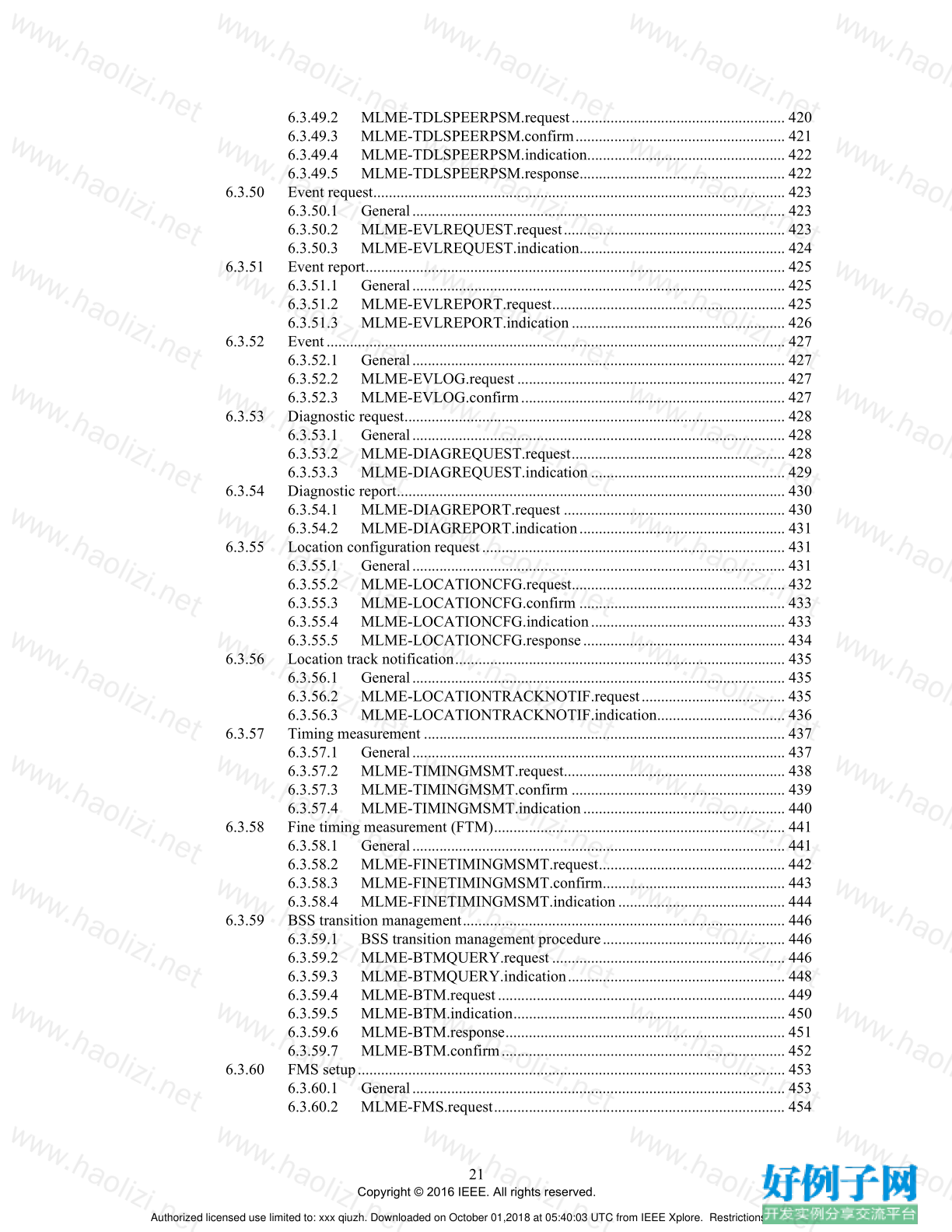
6.3.39.2 MLME-ENABLEMENT.request........................................................ 391
6.3.39.3 MLME-ENABLEMENT.confirm....................................................... 392
6.3.39.4 MLME-ENABLEMENT.indication................................................... 393
6.3.39.5 MLME-ENABLEMENT.response..................................................... 394
6.3.40 Deenablement ........................................................................................................ 395
6.3.40.1 MLME-DEENABLEMENT.request .................................................. 395
6.3.40.2 MLME-DEENABLEMENT.indication.............................................. 396
6.3.41 SA Query support .................................................................................................. 397
6.3.41.1 MLME-SA-QUERY.request............................................................... 397
6.3.41.2 MLME-SA-QUERY.confirm ............................................................. 398
6.3.41.3 MLME-SA-QUERY.indication.......................................................... 398
6.3.41.4 MLME-SA-QUERY.response............................................................ 399
6.3.42 Get TSF timer ........................................................................................................ 400
6.3.42.1 General................................................................................................ 400
6.3.42.2 MLME-GETTSFTIME.request .......................................................... 400
6.3.42.3 MLME-GETTSFTIME.confirm......................................................... 400
6.3.43 Timing Advertisement........................................................................................... 401
6.3.43.1 General................................................................................................ 401
6.3.43.2 MLME-TIMING-ADVERTISEMENT.request ................................. 401
6.3.43.3 MLME-TIMING-ADVERTISEMENT.indication............................. 402
6.3.44 TDLS Discovery.................................................................................................... 403
6.3.44.1 General................................................................................................ 403
6.3.44.2 MLME-TDLSDISCOVERY.request.................................................. 403
6.3.44.3 MLME-TDLSDISCOVERY.confirm................................................. 404
6.3.44.4 MLME-TDLSDISCOVERY.indication ............................................. 405
6.3.44.5 MLME-TDLSDISCOVERY.response ............................................... 405
6.3.45 TDLS direct-link establishment............................................................................. 406
6.3.45.1 General................................................................................................ 406
6.3.45.2 MLME-TDLSSETUPREQUEST.request........................................... 406
6.3.45.3 MLME-TDLSSETUPREQUEST.indication...................................... 407
6.3.45.4 MLME-TDLSSETUPRESPONSE.request......................................... 408
6.3.45.5 MLME-TDLSSETUPRESPONSE.indication.................................... 409
6.3.45.6 MLME-TDLSSETUPCONFIRM.request .......................................... 409
6.3.45.7 MLME-TDLSSETUPCONFIRM.indication...................................... 410
6.3.45.8 MLME-TDLSPOTENTIALPEERSTA.request ................................. 410
6.3.45.9 MLME-TDLSPOTENTIALPEERSTA.confirm ................................ 411
6.3.46 TDLS direct-link teardown.................................................................................... 412
6.3.46.1 General................................................................................................ 412
6.3.46.2 MLME-TDLSTEARDOWN.request.................................................. 412
6.3.46.3 MLME-TDLSTEARDOWN.indication ............................................. 413
6.3.47 TDLS peer U-APSD (TPU)................................................................................... 413
6.3.47.1 General................................................................................................ 413
6.3.47.2 MLME-TDLSPTI.request................................................................... 414
6.3.47.3 MLME-TDLSPTI.confirm.................................................................. 415
6.3.47.4 MLME-TDLSPTI.indication .............................................................. 415
6.3.47.5 MLME-TDLSPTI.response ................................................................ 416
6.3.48 TDLS channel switching ....................................................................................... 417
6.3.48.1 General................................................................................................ 417
6.3.48.2 MLME-TDLSCHANNELSWITCH.request ...................................... 417
6.3.48.3 MLME-TDLSCHANNELSWITCH.confirm..................................... 418
6.3.48.4 MLME-TDLSCHANNELSWITCH.indication.................................. 419
6.3.48.5 MLME-TDLSCHANNELSWITCH.response.................................... 419
6.3.49 TDLS peer PSM..................................................................................................... 420
6.3.49.1 General................................................................................................ 420
Authorized licensed use limited to: xxx qiuzh. Downloaded on October 01,2018 at 05:40:03 UTC from IEEE Xplore. Restrictions apply.
21
Copyright © 2016 IEEE. All rights reserved.
6.3.49.2 MLME-TDLSPEERPSM.request....................................................... 420
6.3.49.3 MLME-TDLSPEERPSM.confirm...................................................... 421
6.3.49.4 MLME-TDLSPEERPSM.indication................................................... 422
6.3.49.5 MLME-TDLSPEERPSM.response..................................................... 422
6.3.50 Event request.......................................................................................................... 423
6.3.50.1 General................................................................................................ 423
6.3.50.2 MLME-EVLREQUEST.request......................................................... 423
6.3.50.3 MLME-EVLREQUEST.indication..................................................... 424
6.3.51 Event report............................................................................................................ 425
6.3.51.1 General................................................................................................ 425
6.3.51.2 MLME-EVLREPORT.request............................................................ 425
6.3.51.3 MLME-EVLREPORT.indication....................................................... 426
6.3.52 Event...................................................................................................................... 427
6.3.52.1 General................................................................................................ 427
6.3.52.2 MLME-EVLOG.request..................................................................... 427
6.3.52.3 MLME-EVLOG.confirm.................................................................... 427
6.3.53 Diagnostic request.................................................................................................. 428
6.3.53.1 General................................................................................................ 428
6.3.53.2 MLME-DIAGREQUEST.request....................................................... 428
6.3.53.3 MLME-DIAGREQUEST.indication .................................................. 429
6.3.54 Diagnostic report.................................................................................................... 430
6.3.54.1 MLME-DIAGREPORT.request ......................................................... 430
6.3.54.2 MLME-DIAGREPORT.indication..................................................... 431
6.3.55 Location configuration request.............................................................................. 431
6.3.55.1 General................................................................................................ 431
6.3.55.2 MLME-LOCATIONCFG.request....................................................... 432
6.3.55.3 MLME-LOCATIONCFG.confirm ..................................................... 433
6.3.55.4 MLME-LOCATIONCFG.indication.................................................. 433
6.3.55.5 MLME-LOCATIONCFG.response.................................................... 434
6.3.56 Location track notification..................................................................................... 435
6.3.56.1 General................................................................................................ 435
6.3.56.2 MLME-LOCATIONTRACKNOTIF.request..................................... 435
6.3.56.3 MLME-LOCATIONTRACKNOTIF.indication................................. 436
6.3.57 Timing measurement ............................................................................................. 437
6.3.57.1 General................................................................................................ 437
6.3.57.2 MLME-TIMINGMSMT.request......................................................... 438
6.3.57.3 MLME-TIMINGMSMT.confirm ....................................................... 439
6.3.57.4 MLME-TIMINGMSMT.indication.................................................... 440
6.3.58 Fine timing measurement (FTM)........................................................................... 441
6.3.58.1 General................................................................................................ 441
6.3.58.2 MLME-FINETIMINGMSMT.request................................................ 442
6.3.58.3 MLME-FINETIMINGMSMT.confirm............................................... 443
6.3.58.4 MLME-FINETIMINGMSMT.indication........................................... 444
6.3.59 BSS transition management................................................................................... 446
6.3.59.1 BSS transition management procedure............................................... 446
6.3.59.2 MLME-BTMQUERY.request ............................................................ 446
6.3.59.3 MLME-BTMQUERY.indication........................................................ 448
6.3.59.4 MLME-BTM.request.......................................................................... 449
6.3.59.5 MLME-BTM.indication...................................................................... 450
6.3.59.6 MLME-BTM.response........................................................................ 451
6.3.59.7 MLME-BTM.confirm......................................................................... 452
6.3.60 FMS setup.............................................................................................................. 453
6.3.60.1 General................................................................................................ 453
6.3.60.2 MLME-FMS.request........................................................................... 454
Authorized licensed use limited to: xxx qiuzh. Downloaded on October 01,2018 at 05:40:03 UTC from IEEE Xplore. Restrictions apply.
22
Copyright © 2016 IEEE. All rights reserved.
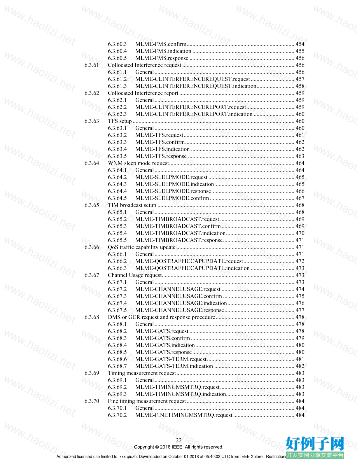
6.3.60.3 MLME-FMS.confirm.......................................................................... 454
6.3.60.4 MLME-FMS.indication ...................................................................... 455
6.3.60.5 MLME-FMS.response ........................................................................ 456
6.3.61 Collocated Interference request............................................................................. 456
6.3.61.1 General................................................................................................ 456
6.3.61.2 MLME-CLINTERFERENCEREQUEST.request.............................. 457
6.3.61.3 MLME-CLINTERFERENCEREQUEST.indication.......................... 458
6.3.62 Collocated Interference report............................................................................... 459
6.3.62.1 General................................................................................................ 459
6.3.62.2 MLME-CLINTERFERENCEREPORT.request................................. 459
6.3.62.3 MLME-CLINTERFERENCEREPORT.indication ............................ 460
6.3.63 TFS setup............................................................................................................... 460
6.3.63.1 General................................................................................................ 460
6.3.63.2 MLME-TFS.request............................................................................ 461
6.3.63.3 MLME-TFS.confirm........................................................................... 462
6.3.63.4 MLME-TFS.indication ....................................................................... 462
6.3.63.5 MLME-TFS.response ......................................................................... 463
6.3.64 WNM sleep mode request...................................................................................... 464
6.3.64.1 General................................................................................................ 464
6.3.64.2 MLME-SLEEPMODE.request........................................................... 465
6.3.64.3 MLME-SLEEPMODE.indication....................................................... 465
6.3.64.4 MLME-SLEEPMODE.response......................................................... 466
6.3.64.5 MLME-SLEEPMODE.confirm.......................................................... 467
6.3.65 TIM broadcast setup .............................................................................................. 468
6.3.65.1 General................................................................................................ 468
6.3.65.2 MLME-TIMBROADCAST.request................................................... 469
6.3.65.3 MLME-TIMBROADCAST.confirm.................................................. 469
6.3.65.4 MLME-TIMBROADCAST.indication............................................... 470
6.3.65.5 MLME-TIMBROADCAST.response................................................. 471
6.3.66 QoS traffic capability update................................................................................. 471
6.3.66.1 General................................................................................................ 471
6.3.66.2 MLME-QOSTRAFFICCAPUPDATE.request................................... 472
6.3.66.3 MLME-QOSTRAFFICCAPUPDATE.indication .............................. 473
6.3.67 Channel Usage request........................................................................................... 473
6.3.67.1 General................................................................................................ 473
6.3.67.2 MLME-CHANNELUSAGE.request .................................................. 474
6.3.67.3 MLME-CHANNELUSAGE.confirm................................................. 475
6.3.67.4 MLME-CHANNELUSAGE.indication.............................................. 476
6.3.67.5 MLME-CHANNELUSAGE.response................................................ 477
6.3.68 DMS or GCR request and response procedure...................................................... 478
6.3.68.1 General................................................................................................ 478
6.3.68.2 MLME-GATS.request ........................................................................ 478
6.3.68.3 MLME-GATS.confirm....................................................................... 479
6.3.68.4 MLME-GATS.indication.................................................................... 480
6.3.68.5 MLME-GATS.response...................................................................... 480
6.3.68.6 MLME-GATS-TERM.request............................................................ 481
6.3.68.7 MLME-GATS-TERM.indication ....................................................... 482
6.3.69 Timing measurement request................................................................................. 483
6.3.69.1 General................................................................................................ 483
6.3.69.2 MLME-TIMINGMSMTRQ.request................................................... 483
6.3.69.3 MLME-TIMINGMSMTRQ.indication............................................... 483
6.3.70 Fine timing measurement request.......................................................................... 484
6.3.70.1 General................................................................................................ 484
6.3.70.2 MLME-FINETIMINGMSMTRQ.request.......................................... 484
Authorized licensed use limited to: xxx qiuzh. Downloaded on October 01,2018 at 05:40:03 UTC from IEEE Xplore. Restrictions apply.
23
Copyright © 2016 IEEE. All rights reserved.
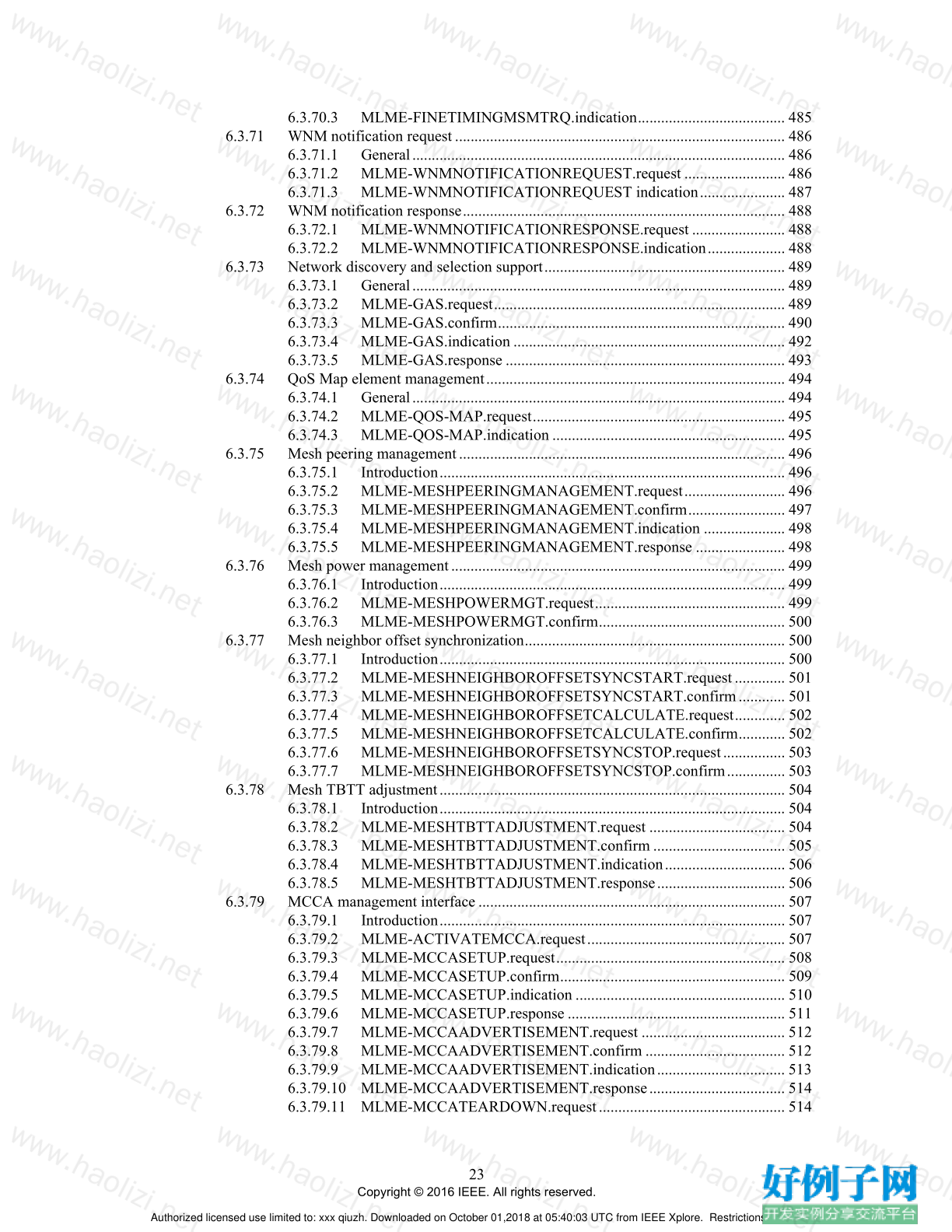
6.3.70.3 MLME-FINETIMINGMSMTRQ.indication...................................... 485
6.3.71 WNM notification request..................................................................................... 486
6.3.71.1 General................................................................................................ 486
6.3.71.2 MLME-WNMNOTIFICATIONREQUEST.request .......................... 486
6.3.71.3 MLME-WNMNOTIFICATIONREQUEST indication...................... 487
6.3.72 WNM notification response................................................................................... 488
6.3.72.1 MLME-WNMNOTIFICATIONRESPONSE.request ........................ 488
6.3.72.2 MLME-WNMNOTIFICATIONRESPONSE.indication.................... 488
6.3.73 Network discovery and selection support.............................................................. 489
6.3.73.1 General................................................................................................ 489
6.3.73.2 MLME-GAS.request........................................................................... 489
6.3.73.3 MLME-GAS.confirm.......................................................................... 490
6.3.73.4 MLME-GAS.indication ...................................................................... 492
6.3.73.5 MLME-GAS.response ........................................................................ 493
6.3.74 QoS Map element management............................................................................. 494
6.3.74.1 General................................................................................................ 494
6.3.74.2 MLME-QOS-MAP.request................................................................. 495
6.3.74.3 MLME-QOS-MAP.indication ............................................................ 495
6.3.75 Mesh peering management.................................................................................... 496
6.3.75.1 Introduction......................................................................................... 496
6.3.75.2 MLME-MESHPEERINGMANAGEMENT.request.......................... 496
6.3.75.3 MLME-MESHPEERINGMANAGEMENT.confirm......................... 497
6.3.75.4 MLME-MESHPEERINGMANAGEMENT.indication ..................... 498
6.3.75.5 MLME-MESHPEERINGMANAGEMENT.response ....................... 498
6.3.76 Mesh power management...................................................................................... 499
6.3.76.1 Introduction......................................................................................... 499
6.3.76.2 MLME-MESHPOWERMGT.request................................................. 499
6.3.76.3 MLME-MESHPOWERMGT.confirm................................................ 500
6.3.77 Mesh neighbor offset synchronization................................................................... 500
6.3.77.1 Introduction......................................................................................... 500
6.3.77.2 MLME-MESHNEIGHBOROFFSETSYNCSTART.request............. 501
6.3.77.3 MLME-MESHNEIGHBOROFFSETSYNCSTART.confirm............ 501
6.3.77.4 MLME-MESHNEIGHBOROFFSETCALCULATE.request............. 502
6.3.77.5 MLME-MESHNEIGHBOROFFSETCALCULATE.confirm............ 502
6.3.77.6 MLME-MESHNEIGHBOROFFSETSYNCSTOP.request................ 503
6.3.77.7 MLME-MESHNEIGHBOROFFSETSYNCSTOP.confirm............... 503
6.3.78 Mesh TBTT adjustment......................................................................................... 504
6.3.78.1 Introduction......................................................................................... 504
6.3.78.2 MLME-MESHTBTTADJUSTMENT.request ................................... 504
6.3.78.3 MLME-MESHTBTTADJUSTMENT.confirm .................................. 505
6.3.78.4 MLME-MESHTBTTADJUSTMENT.indication............................... 506
6.3.78.5 MLME-MESHTBTTADJUSTMENT.response................................. 506
6.3.79 MCCA management interface............................................................................... 507
6.3.79.1 Introduction......................................................................................... 507
6.3.79.2 MLME-ACTIVATEMCCA.request................................................... 507
6.3.79.3 MLME-MCCASETUP.request........................................................... 508
6.3.79.4 MLME-MCCASETUP.confirm.......................................................... 509
6.3.79.5 MLME-MCCASETUP.indication ...................................................... 510
6.3.79.6 MLME-MCCASETUP.response ........................................................ 511
6.3.79.7 MLME-MCCAADVERTISEMENT.request ..................................... 512
6.3.79.8 MLME-MCCAADVERTISEMENT.confirm .................................... 512
6.3.79.9 MLME-MCCAADVERTISEMENT.indication................................. 513
6.3.79.10 MLME-MCCAADVERTISEMENT.response................................... 514
6.3.79.11 MLME-MCCATEARDOWN.request................................................ 514
Authorized licensed use limited to: xxx qiuzh. Downloaded on October 01,2018 at 05:40:03 UTC from IEEE Xplore. Restrictions apply.
24
Copyright © 2016 IEEE. All rights reserved.
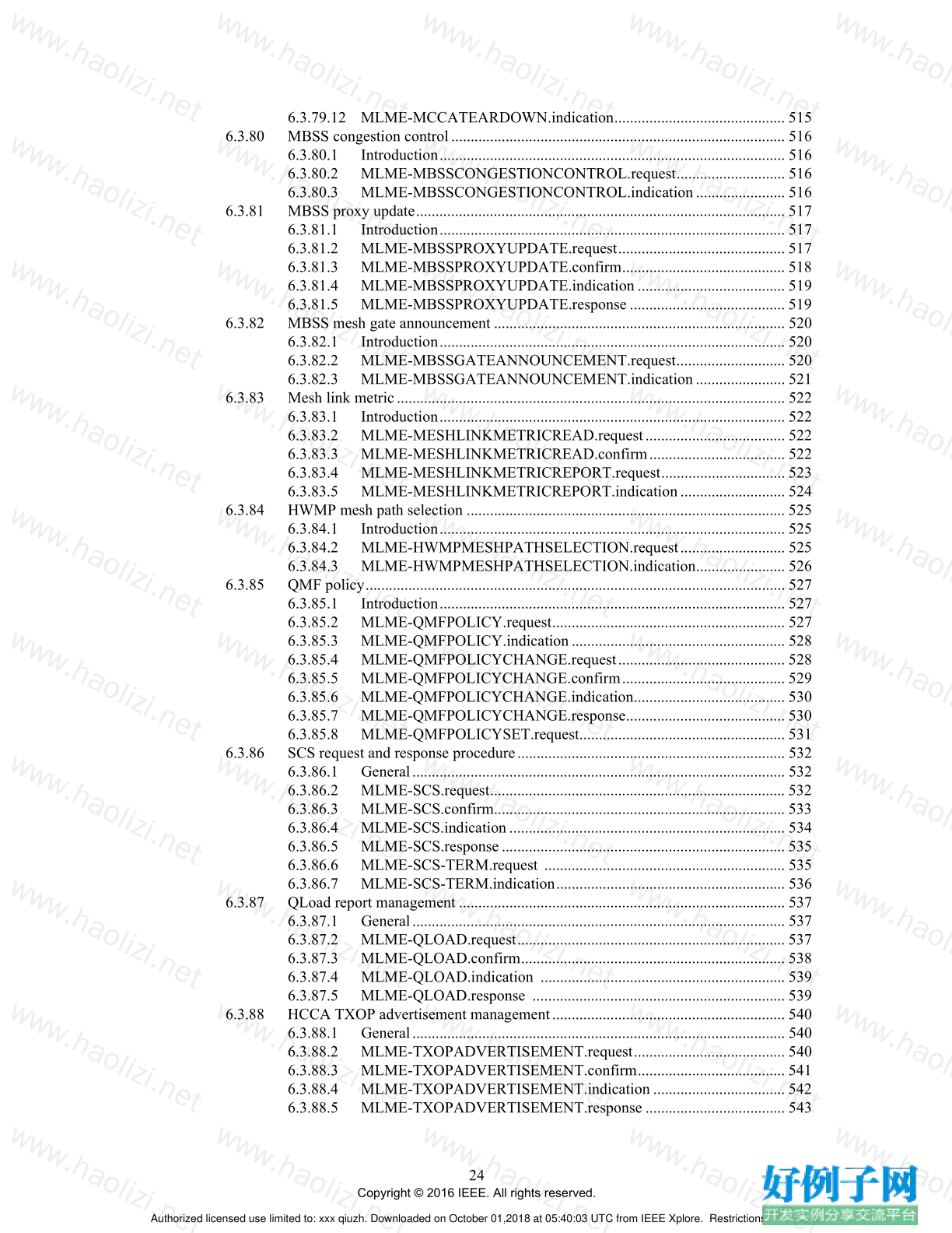
6.3.79.12 MLME-MCCATEARDOWN.indication............................................ 515
6.3.80 MBSS congestion control...................................................................................... 516
6.3.80.1 Introduction......................................................................................... 516
6.3.80.2 MLME-MBSSCONGESTIONCONTROL.request............................ 516
6.3.80.3 MLME-MBSSCONGESTIONCONTROL.indication....................... 516
6.3.81 MBSS proxy update............................................................................................... 517
6.3.81.1 Introduction......................................................................................... 517
6.3.81.2 MLME-MBSSPROXYUPDATE.request........................................... 517
6.3.81.3 MLME-MBSSPROXYUPDATE.confirm.......................................... 518
6.3.81.4 MLME-MBSSPROXYUPDATE.indication ...................................... 519
6.3.81.5 MLME-MBSSPROXYUPDATE.response ........................................ 519
6.3.82 MBSS mesh gate announcement ........................................................................... 520
6.3.82.1 Introduction......................................................................................... 520
6.3.82.2 MLME-MBSSGATEANNOUNCEMENT.request............................ 520
6.3.82.3 MLME-MBSSGATEANNOUNCEMENT.indication....................... 521
6.3.83 Mesh link metric.................................................................................................... 522
6.3.83.1 Introduction......................................................................................... 522
6.3.83.2 MLME-MESHLINKMETRICREAD.request.................................... 522
6.3.83.3 MLME-MESHLINKMETRICREAD.confirm................................... 522
6.3.83.4 MLME-MESHLINKMETRICREPORT.request................................ 523
6.3.83.5 MLME-MESHLINKMETRICREPORT.indication........................... 524
6.3.84 HWMP mesh path selection .................................................................................. 525
6.3.84.1 Introduction......................................................................................... 525
6.3.84.2 MLME-HWMPMESHPATHSELECTION.request........................... 525
6.3.84.3 MLME-HWMPMESHPATHSELECTION.indication....................... 526
6.3.85 QMF policy............................................................................................................ 527
6.3.85.1 Introduction......................................................................................... 527
6.3.85.2 MLME-QMFPOLICY.request............................................................ 527
6.3.85.3 MLME-QMFPOLICY.indication....................................................... 528
6.3.85.4 MLME-QMFPOLICYCHANGE.request........................................... 528
6.3.85.5 MLME-QMFPOLICYCHANGE.confirm.......................................... 529
6.3.85.6 MLME-QMFPOLICYCHANGE.indication....................................... 530
6.3.85.7 MLME-QMFPOLICYCHANGE.response......................................... 530
6.3.85.8 MLME-QMFPOLICYSET.request..................................................... 531
6.3.86 SCS request and response procedure..................................................................... 532
6.3.86.1 General................................................................................................ 532
6.3.86.2 MLME-SCS.request............................................................................ 532
6.3.86.3 MLME-SCS.confirm........................................................................... 533
6.3.86.4 MLME-SCS.indication....................................................................... 534
6.3.86.5 MLME-SCS.response......................................................................... 535
6.3.86.6 MLME-SCS-TERM.request .............................................................. 535
6.3.86.7 MLME-SCS-TERM.indication........................................................... 536
6.3.87 QLoad report management .................................................................................... 537
6.3.87.1 General................................................................................................ 537
6.3.87.2 MLME-QLOAD.request..................................................................... 537
6.3.87.3 MLME-QLOAD.confirm.................................................................... 538
6.3.87.4 MLME-QLOAD.indication ............................................................... 539
6.3.87.5 MLME-QLOAD.response ................................................................. 539
6.3.88 HCCA TXOP advertisement management............................................................ 540
6.3.88.1 General................................................................................................ 540
6.3.88.2 MLME-TXOPADVERTISEMENT.request....................................... 540
6.3.88.3 MLME-TXOPADVERTISEMENT.confirm...................................... 541
6.3.88.4 MLME-TXOPADVERTISEMENT.indication .................................. 542
6.3.88.5 MLME-TXOPADVERTISEMENT.response .................................... 543
Authorized licensed use limited to: xxx qiuzh. Downloaded on October 01,2018 at 05:40:03 UTC from IEEE Xplore. Restrictions apply.
25
Copyright © 2016 IEEE. All rights reserved.
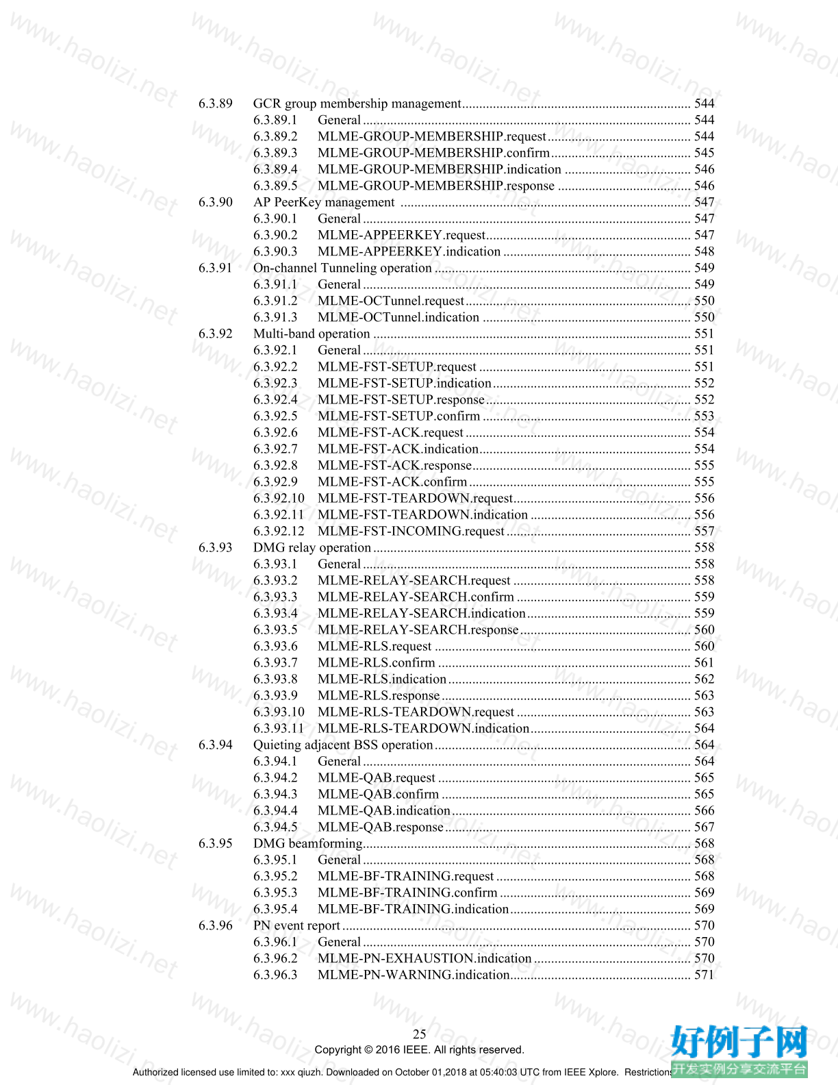
6.3.89 GCR group membership management................................................................... 544
6.3.89.1 General................................................................................................ 544
6.3.89.2 MLME-GROUP-MEMBERSHIP.request.......................................... 544
6.3.89.3 MLME-GROUP-MEMBERSHIP.confirm......................................... 545
6.3.89.4 MLME-GROUP-MEMBERSHIP.indication ..................................... 546
6.3.89.5 MLME-GROUP-MEMBERSHIP.response ....................................... 546
6.3.90 AP PeerKey management ..................................................................................... 547
6.3.90.1 General................................................................................................ 547
6.3.90.2 MLME-APPEERKEY.request............................................................ 547
6.3.90.3 MLME-APPEERKEY.indication....................................................... 548
6.3.91 On-channel Tunneling operation........................................................................... 549
6.3.91.1 General................................................................................................ 549
6.3.91.2 MLME-OCTunnel.request.................................................................. 550
6.3.91.3 MLME-OCTunnel.indication ............................................................. 550
6.3.92 Multi-band operation ............................................................................................. 551
6.3.92.1 General................................................................................................ 551
6.3.92.2 MLME-FST-SETUP.request .............................................................. 551
6.3.92.3 MLME-FST-SETUP.indication.......................................................... 552
6.3.92.4 MLME-FST-SETUP.response............................................................ 552
6.3.92.5 MLME-FST-SETUP.confirm............................................................. 553
6.3.92.6 MLME-FST-ACK.request.................................................................. 554
6.3.92.7 MLME-FST-ACK.indication.............................................................. 554
6.3.92.8 MLME-FST-ACK.response................................................................ 555
6.3.92.9 MLME-FST-ACK.confirm................................................................. 555
6.3.92.10 MLME-FST-TEARDOWN.request.................................................... 556
6.3.92.11 MLME-FST-TEARDOWN.indication............................................... 556
6.3.92.12 MLME-FST-INCOMING.request...................................................... 557
6.3.93 DMG relay operation............................................................................................. 558
6.3.93.1 General................................................................................................ 558
6.3.93.2 MLME-RELAY-SEARCH.request .................................................... 558
6.3.93.3 MLME-RELAY-SEARCH.confirm................................................... 559
6.3.93.4 MLME-RELAY-SEARCH.indication................................................ 559
6.3.93.5 MLME-RELAY-SEARCH.response.................................................. 560
6.3.93.6 MLME-RLS.request ........................................................................... 560
6.3.93.7 MLME-RLS.confirm .......................................................................... 561
6.3.93.8 MLME-RLS.indication....................................................................... 562
6.3.93.9 MLME-RLS.response......................................................................... 563
6.3.93.10 MLME-RLS-TEARDOWN.request................................................... 563
6.3.93.11 MLME-RLS-TEARDOWN.indication............................................... 564
6.3.94 Quieting adjacent BSS operation........................................................................... 564
6.3.94.1 General................................................................................................ 564
6.3.94.2 MLME-QAB.request .......................................................................... 565
6.3.94.3 MLME-QAB.confirm......................................................................... 565
6.3.94.4 MLME-QAB.indication...................................................................... 566
6.3.94.5 MLME-QAB.response........................................................................ 567
6.3.95 DMG beamforming................................................................................................ 568
6.3.95.1 General................................................................................................ 568
6.3.95.2 MLME-BF-TRAINING.request......................................................... 568
6.3.95.3 MLME-BF-TRAINING.confirm........................................................ 569
6.3.95.4 MLME-BF-TRAINING.indication..................................................... 569
6.3.96 PN event report...................................................................................................... 570
6.3.96.1 General................................................................................................ 570
6.3.96.2 MLME-PN-EXHAUSTION.indication.............................................. 570
6.3.96.3 MLME-PN-WARNING.indication..................................................... 571
Authorized licensed use limited to: xxx qiuzh. Downloaded on October 01,2018 at 05:40:03 UTC from IEEE Xplore. Restrictions apply.
26
Copyright © 2016 IEEE. All rights reserved.
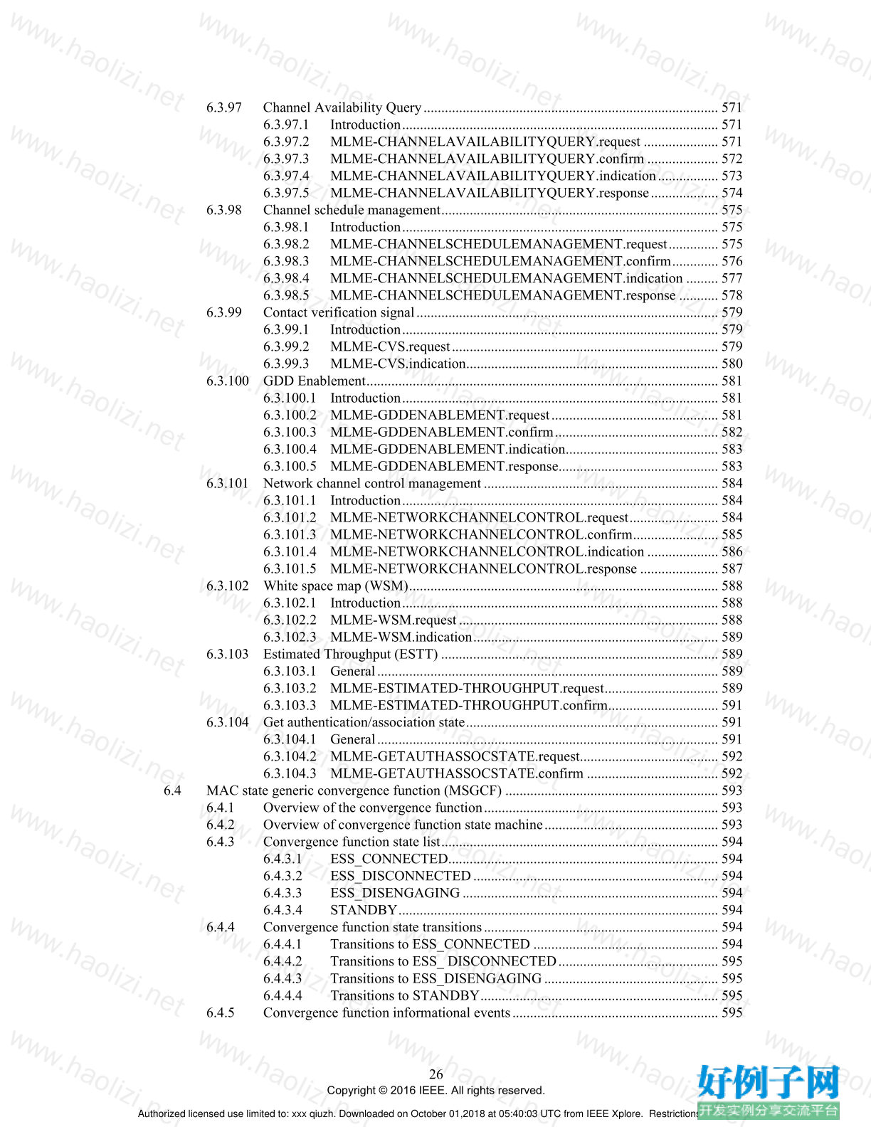
6.3.97 Channel Availability Query................................................................................... 571
6.3.97.1 Introduction......................................................................................... 571
6.3.97.2 MLME-CHANNELAVAILABILITYQUERY.request ..................... 571
6.3.97.3 MLME-CHANNELAVAILABILITYQUERY.confirm .................... 572
6.3.97.4 MLME-CHANNELAVAILABILITYQUERY.indication................. 573
6.3.97.5 MLME-CHANNELAVAILABILITYQUERY.response................... 574
6.3.98 Channel schedule management.............................................................................. 575
6.3.98.1 Introduction......................................................................................... 575
6.3.98.2 MLME-CHANNELSCHEDULEMANAGEMENT.request.............. 575
6.3.98.3 MLME-CHANNELSCHEDULEMANAGEMENT.confirm............. 576
6.3.98.4 MLME-CHANNELSCHEDULEMANAGEMENT.indication ......... 577
6.3.98.5 MLME-CHANNELSCHEDULEMANAGEMENT.response ........... 578
6.3.99 Contact verification signal..................................................................................... 579
6.3.99.1 Introduction......................................................................................... 579
6.3.99.2 MLME-CVS.request........................................................................... 579
6.3.99.3 MLME-CVS.indication....................................................................... 580
6.3.100 GDD Enablement................................................................................................... 581
6.3.100.1 Introduction......................................................................................... 581
6.3.100.2 MLME-GDDENABLEMENT.request............................................... 581
6.3.100.3 MLME-GDDENABLEMENT.confirm.............................................. 582
6.3.100.4 MLME-GDDENABLEMENT.indication........................................... 583
6.3.100.5 MLME-GDDENABLEMENT.response............................................. 583
6.3.101 Network channel control management.................................................................. 584
6.3.101.1 Introduction......................................................................................... 584
6.3.101.2 MLME-NETWORKCHANNELCONTROL.request......................... 584
6.3.101.3 MLME-NETWORKCHANNELCONTROL.confirm........................ 585
6.3.101.4 MLME-NETWORKCHANNELCONTROL.indication .................... 586
6.3.101.5 MLME-NETWORKCHANNELCONTROL.response ...................... 587
6.3.102 White space map (WSM)....................................................................................... 588
6.3.102.1 Introduction......................................................................................... 588
6.3.102.2 MLME-WSM.request......................................................................... 588
6.3.102.3 MLME-WSM.indication..................................................................... 589
6.3.103 Estimated Throughput (ESTT) .............................................................................. 589
6.3.103.1 General................................................................................................ 589
6.3.103.2 MLME-ESTIMATED-THROUGHPUT.request................................ 589
6.3.103.3 MLME-ESTIMATED-THROUGHPUT.confirm............................... 591
6.3.104 Get authentication/association state....................................................................... 591
6.3.104.1 General................................................................................................ 591
6.3.104.2 MLME-GETAUTHASSOCSTATE.request....................................... 592
6.3.104.3 MLME-GETAUTHASSOCSTATE.confirm ..................................... 592
6.4 MAC state generic convergence function (MSGCF) ............................................................ 593
6.4.1 Overview of the convergence function.................................................................. 593
6.4.2 Overview of convergence function state machine................................................. 593
6.4.3 Convergence function state list.............................................................................. 594
6.4.3.1 ESS_CONNECTED............................................................................ 594
6.4.3.2 ESS_DISCONNECTED..................................................................... 594
6.4.3.3 ESS_DISENGAGING........................................................................ 594
6.4.3.4 STANDBY.......................................................................................... 594
6.4.4 Convergence function state transitions.................................................................. 594
6.4.4.1 Transitions to ESS_CONNECTED .................................................... 594
6.4.4.2 Transitions to ESS_ DISCONNECTED............................................. 595
6.4.4.3 Transitions to ESS_DISENGAGING................................................. 595
6.4.4.4 Transitions to STANDBY................................................................... 595
6.4.5 Convergence function informational events.......................................................... 595
Authorized licensed use limited to: xxx qiuzh. Downloaded on October 01,2018 at 05:40:03 UTC from IEEE Xplore. Restrictions apply.
27
Copyright © 2016 IEEE. All rights reserved.
6.4.6 MAC state generic convergence SAP.................................................................... 595
6.4.7 ESS status reporting............................................................................................... 596
6.4.7.1 MSGCF-ESS-LINK-UP.indication..................................................... 596
6.4.7.2 MSGCF-ESS-LINK-DOWN.indication............................................. 597
6.4.7.3 MSGCF-ESS-LINK-GOING-DOWN.indication............................... 598
6.4.7.4 MSGCF-ESS-LINK-EVENT-ROLLBACK.indication...................... 599
6.4.7.5 MSGCF-ESS-LINK-DETECTED.indication..................................... 600
6.4.7.6 MSGCF-ESS-LINK-SCAN.request ................................................... 601
6.4.7.7 MSGCF-ESS-LINK-SCAN.confirm .................................................. 602
6.4.8 Network configuration........................................................................................... 602
6.4.8.1 MSGCF-ESS-LINK-CAPABILITY.request ...................................... 602
6.4.8.2 MSGCF-ESS-LINK-CAPABILITY.confirm..................................... 603
6.4.8.3 MSGCF-ESS-LINK-PARAMETERS.request.................................... 604
6.4.8.4 MSGCF-ESS-LINK-PARAMETERS.confirm................................... 606
6.4.8.5 MSGCF-GET-ESS-LINK-PARAMETERS.request........................... 606
6.4.8.6 MSGCF-GET-ESS-LINK-PARAMETERS.confirm ......................... 607
6.4.9 Network events...................................................................................................... 607
6.4.9.1 MSGCF-ESS-LINK-THRESHOLD-REPORT.indication................. 607
6.4.10 Network command interface.................................................................................. 608
6.4.10.1 MSGCF-ESS-LINK-COMMAND.request......................................... 608
6.4.11 MAC state SME SAP—mobility management ..................................................... 609
6.4.11.1 MSSME-ESS-LINK-GOING-DOWN.indication............................... 609
6.5 PLME SAP interface ............................................................................................................. 610
6.5.1 General................................................................................................................... 610
6.5.2 PLME-RESET.request........................................................................................... 610
6.5.2.1 Function .............................................................................................. 610
6.5.2.2 Semantics of the service primitive...................................................... 610
6.5.2.3 When generated................................................................................... 610
6.5.2.4 Effect of receipt................................................................................... 610
6.5.3 PLME-CHARACTERISTICS.request .................................................................. 611
6.5.3.1 Function .............................................................................................. 611
6.5.3.2 Semantics of the service primitive...................................................... 611
6.5.3.3 When generated................................................................................... 611
6.5.3.4 Effect of receipt................................................................................... 611
6.5.4 PLME-CHARACTERISTICS.confirm ................................................................. 611
6.5.4.1 Function .............................................................................................. 611
6.5.4.2 Semantics of the service primitive...................................................... 611
6.5.4.3 When generated................................................................................... 614
6.5.4.4 Effect of receipt................................................................................... 614
6.5.5 PLME-TXTIME.request........................................................................................ 614
6.5.5.1 Function .............................................................................................. 614
6.5.5.2 Semantics of the service primitive...................................................... 614
6.5.5.3 When generated................................................................................... 614
6.5.5.4 Effect of receipt................................................................................... 614
6.5.6 PLME-TXTIME.confirm....................................................................................... 615
6.5.6.1 Function .............................................................................................. 615
6.5.6.2 Semantics of the service primitive...................................................... 615
6.5.6.3 When generated................................................................................... 615
6.5.6.4 Effect of receipt................................................................................... 615
7. DS SAP specification......................................................................................................................... 616
7.1 Introduction............................................................................................................................ 616
7.2 SAP primitives....................................................................................................................... 616
Authorized licensed use limited to: xxx qiuzh. Downloaded on October 01,2018 at 05:40:03 UTC from IEEE Xplore. Restrictions apply.
28
Copyright © 2016 IEEE. All rights reserved.
7.2.1 General................................................................................................................... 616
7.2.2 MSDU transfer....................................................................................................... 617
7.2.2.1 General................................................................................................ 617
7.2.2.2 DS-UNITDATA.request..................................................................... 617
7.2.2.3 DS-UNITDATA.indication................................................................. 617
7.2.3 Mapping updates.................................................................................................... 618
7.2.3.1 General................................................................................................ 618
7.2.3.2 DS-STA-NOTIFY.request.................................................................. 618
8. PHY service specification.................................................................................................................. 620
8.1 Scope...................................................................................................................................... 620
8.2 PHY functions........................................................................................................................ 620
8.3 Detailed PHY service specifications...................................................................................... 620
8.3.1 Scope and field of application ............................................................................... 620
8.3.2 Overview of the service......................................................................................... 620
8.3.3 Overview of interactions........................................................................................ 620
8.3.4 Basic service and options....................................................................................... 620
8.3.4.1 PHY SAP peer-to-peer service primitives.......................................... 620
8.3.4.2 PHY SAP inter-(sub)layer service primitives..................................... 621
8.3.4.3 PHY SAP service primitives parameters............................................ 621
8.3.4.4 Vector descriptions ............................................................................. 622
8.3.5 PHY SAP detailed service specification................................................................ 623
8.3.5.1 Introduction......................................................................................... 623
8.3.5.2 PHY-DATA.request............................................................................ 623
8.3.5.3 PHY-DATA.indication....................................................................... 623
8.3.5.4 PHY-DATA.confirm........................................................................... 624
8.3.5.5 PHY-TXSTART.request..................................................................... 624
8.3.5.6 PHY-TXSTART.confirm.................................................................... 625
8.3.5.7 PHY-TXEND.request......................................................................... 626
8.3.5.8 PHY-TXEND.confirm........................................................................ 626
8.3.5.9 PHY-TXHEADEREND.indication..................................................... 627
8.3.5.10 PHY-CCARESET.request .................................................................. 627
8.3.5.11 PHY-CCARESET.confirm................................................................. 628
8.3.5.12 PHY-CCA.indication.......................................................................... 628
8.3.5.13 PHY-RXSTART.indication................................................................ 632
8.3.5.14 PHY-RXEND.indication..................................................................... 632
8.3.5.15 PHY-CONFIG.request........................................................................ 633
8.3.5.16 PHY-CONFIG.confirm....................................................................... 634
8.3.5.17 PHY-TXBUSY.indication .................................................................. 634
8.4 PHY management.................................................................................................................. 635
9. Frame formats.................................................................................................................................... 636
9.1 General requirements............................................................................................................. 636
9.2 MAC frame formats............................................................................................................... 636
9.2.1 Basic components.................................................................................................. 636
9.2.2 Conventions........................................................................................................... 636
9.2.3 General frame format............................................................................................. 637
9.2.4 Frame fields ........................................................................................................... 638
9.2.4.1 Frame Control field............................................................................. 638
9.2.4.2 Duration/ID field................................................................................. 644
9.2.4.3 Address fields...................................................................................... 645
9.2.4.4 Sequence Control field........................................................................ 646
Authorized licensed use limited to: xxx qiuzh. Downloaded on October 01,2018 at 05:40:03 UTC from IEEE Xplore. Restrictions apply.
29
Copyright © 2016 IEEE. All rights reserved.
9.2.4.5 QoS Control field................................................................................ 647
9.2.4.6 HT Control field.................................................................................. 654
9.2.4.7 Frame Body field ................................................................................ 661
9.2.4.8 FCS field............................................................................................. 665
9.2.5 Duration/ID field (QoS STA)................................................................................ 665
9.2.5.1 General................................................................................................ 665
9.2.5.2 Setting for single and multiple protection under enhanced
distributed channel access (EDCA) .................................................... 665
9.2.5.3 Setting for QoS CF-Poll frames.......................................................... 667
9.2.5.4 Setting for frames sent by a TXOP holder under HCCA.................... 668
9.2.5.5 Settings within a PSMP sequence....................................................... 668
9.2.5.6 Settings within a dual CTS sequence.................................................. 668
9.2.5.7 Setting for control response frames .................................................... 669
9.2.5.8 Setting for other response frames........................................................ 669
9.3 Format of individual frame types........................................................................................... 669
9.3.1 Control frames ....................................................................................................... 669
9.3.1.1 Format of Control frames.................................................................... 669
9.3.1.2 RTS frame format ............................................................................... 670
9.3.1.3 CTS frame format ............................................................................... 670
9.3.1.4 Ack frame format................................................................................ 671
9.3.1.5 PS-Poll frame format .......................................................................... 671
9.3.1.6 CF-End frame format.......................................................................... 672
9.3.1.7 CF-End CF-Ack frame format.......................................................... 672
9.3.1.8 BlockAckReq frame format................................................................ 672
9.3.1.9 BlockAck frame format ...................................................................... 676
9.3.1.10 Control Wrapper frame....................................................................... 680
9.3.1.11 Poll frame format................................................................................ 681
9.3.1.12 Service period request (SPR) frame format........................................ 681
9.3.1.13 Grant frame format.............................................................................. 682
9.3.1.14 DMG CTS frame format..................................................................... 683
9.3.1.15 DMG DTS frame format..................................................................... 683
9.3.1.16 Sector sweep (SSW) frame format...................................................... 683
9.3.1.17 Sector sweep feedback (SSW-Feedback) frame format ..................... 684
9.3.1.18 Sector sweep Ack (SSW-Ack) frame format...................................... 684
9.3.1.19 Grant Ack frame format...................................................................... 685
9.3.1.20 VHT NDP Announcement frame format............................................ 685
9.3.1.21 Beamforming Report Poll frame format............................................. 687
9.3.2 Data frames............................................................................................................ 687
9.3.2.1 Format of Data frames ........................................................................ 687
9.3.2.2 Aggregate MSDU (A-MSDU) format ................................................ 690
9.3.3 Management frames............................................................................................... 692
9.3.3.1 Terminology of Management frames and MMPDUs......................... 692
9.3.3.2 Format of Management frames........................................................... 692
9.3.3.3 Beacon frame format........................................................................... 694
9.3.3.4 ATIM frame format ............................................................................ 698
9.3.3.5 Disassociation frame format ............................................................... 698
9.3.3.6 Association Request frame format...................................................... 699
9.3.3.7 Association Response frame format ................................................... 700
9.3.3.8 Reassociation Request frame format................................................... 702
9.3.3.9 Reassociation Response frame format................................................ 704
9.3.3.10 Probe Request frame format ............................................................... 706
9.3.3.11 Probe Response frame format............................................................. 708
9.3.3.12 Authentication frame format............................................................... 712
9.3.3.13 Deauthentication ................................................................................. 715
Authorized licensed use limited to: xxx qiuzh. Downloaded on October 01,2018 at 05:40:03 UTC from IEEE Xplore. Restrictions apply.
30
Copyright © 2016 IEEE. All rights reserved.
9.3.3.14 Action frame format............................................................................ 715
9.3.3.15 Action No Ack frame format.............................................................. 716
9.3.3.16 Timing Advertisement frame format .................................................. 716
9.3.4 Extension frames.................................................................................................... 716
9.3.4.1 Format of Extension frames................................................................ 716
9.3.4.2 DMG Beacon ...................................................................................... 717
9.3.5 Frame addressing in an MBSS............................................................................... 721
9.4 Management and Extension frame body components........................................................... 723
9.4.1 Fields that are not elements ................................................................................... 723
9.4.1.1 Authentication Algorithm Number field............................................. 723
9.4.1.2 Authentication Transaction Sequence Number field.......................... 724
9.4.1.3 Beacon Interval field........................................................................... 724
9.4.1.4 Capability Information field................................................................ 724
9.4.1.5 Current AP Address field.................................................................... 727
9.4.1.6 Listen Interval field............................................................................. 727
9.4.1.7 Reason Code field............................................................................... 728
9.4.1.8 AID field............................................................................................. 731
9.4.1.9 Status Code field................................................................................. 731
9.4.1.10 Timestamp field .................................................................................. 736
9.4.1.11 Action field ......................................................................................... 736
9.4.1.12 Dialog Token field.............................................................................. 738
9.4.1.13 DLS Timeout Value field.................................................................... 738
9.4.1.14 Block Ack Parameter Set field............................................................ 738
9.4.1.15 Block Ack Timeout Value field.......................................................... 739
9.4.1.16 DELBA Parameter Set field................................................................ 739
9.4.1.17 QoS Info field...................................................................................... 739
9.4.1.18 Measurement Pilot Interval field......................................................... 741
9.4.1.19 Max Transmit Power field .................................................................. 741
9.4.1.20 Transmit Power Used field ................................................................. 741
9.4.1.21 Channel Width field............................................................................ 741
9.4.1.22 Operating Class and Channel field...................................................... 742
9.4.1.23 SM Power Control field...................................................................... 742
9.4.1.24 PCO Phase Control field..................................................................... 743
9.4.1.25 PSMP Parameter Set field................................................................... 743
9.4.1.26 PSMP STA Info field.......................................................................... 744
9.4.1.27 MIMO Control field............................................................................ 745
9.4.1.28 CSI Report field.................................................................................. 746
9.4.1.29 Noncompressed Beamforming Report field ....................................... 748
9.4.1.30 Compressed Beamforming Report field ............................................. 750
9.4.1.31 Antenna Selection Indices field .......................................................... 753
9.4.1.32 Organization Identifier field................................................................ 753
9.4.1.33 Rate Identification field ...................................................................... 754
9.4.1.34 GAS Query Response Fragment ID field ........................................... 755
9.4.1.35 Venue Info field.................................................................................. 756
9.4.1.36 Target Channel.................................................................................... 759
9.4.1.37 Operating Class................................................................................... 759
9.4.1.38 Send-Confirm field ............................................................................. 759
9.4.1.39 Anti-Clogging Token field.................................................................. 759
9.4.1.40 Scalar field .......................................................................................... 760
9.4.1.41 Finite field element (FFE) field .......................................................... 760
9.4.1.42 Confirm field....................................................................................... 760
9.4.1.43 Finite Cyclic Group field .................................................................... 760
9.4.1.44 TXOP Reservation field...................................................................... 760
9.4.1.45 Relay Capable STA Info field............................................................. 761
Authorized licensed use limited to: xxx qiuzh. Downloaded on October 01,2018 at 05:40:03 UTC from IEEE Xplore. Restrictions apply.
31
Copyright © 2016 IEEE. All rights reserved.
9.4.1.46 Band ID field....................................................................................... 761
9.4.1.47 DMG Parameters field........................................................................ 761
9.4.1.48 VHT MIMO Control field................................................................... 763
9.4.1.49 VHT Compressed Beamforming Report field.................................... 764
9.4.1.50 TVHT Compressed Beamforming Report field.................................. 773
9.4.1.51 MU Exclusive Beamforming Report field.......................................... 774
9.4.1.52 TVHT MU Exclusive Beamforming Report field .............................. 778
9.4.1.53 Operating Mode field.......................................................................... 778
9.4.1.54 Membership Status Array field........................................................... 782
9.4.1.55 User Position Array field .................................................................... 782
9.4.1.56 Device Location Information Body field............................................ 782
9.4.1.57 WSM Type field and WSM Information field.................................... 783
9.4.2 Elements................................................................................................................. 784
9.4.2.1 General................................................................................................ 784
9.4.2.2 SSID element ...................................................................................... 790
9.4.2.3 Supported Rates and BSS Membership Selectors element................. 790
9.4.2.4 DSSS Parameter Set element.............................................................. 792
9.4.2.5 CF Parameter Set element................................................................... 792
9.4.2.6 TIM element........................................................................................ 792
9.4.2.7 IBSS Parameter Set element............................................................... 795
9.4.2.8 Challenge Text element ...................................................................... 795
9.4.2.9 Country element.................................................................................. 795
9.4.2.10 Request element.................................................................................. 798
9.4.2.11 Extended Request element.................................................................. 798
9.4.2.12 ERP element........................................................................................ 799
9.4.2.13 Extended Supported Rates and BSS Membership Selectors element. 799
9.4.2.14 Power Constraint element................................................................... 800
9.4.2.15 Power Capability element................................................................... 800
9.4.2.16 TPC Request element.......................................................................... 801
9.4.2.17 TPC Report element............................................................................ 801
9.4.2.18 Supported Channels element............................................................... 802
9.4.2.19 Channel Switch Announcement element............................................ 802
9.4.2.20 Secondary Channel Offset element..................................................... 803
9.4.2.21 Measurement Request element ........................................................... 804
9.4.2.22 Measurement Report element ............................................................. 835
9.4.2.23 Quiet element...................................................................................... 881
9.4.2.24 IBSS DFS element.............................................................................. 881
9.4.2.25 RSNE .................................................................................................. 882
9.4.2.26 Vendor Specific element..................................................................... 890
9.4.2.27 Extended Capabilities element............................................................ 890
9.4.2.28 BSS Load element............................................................................... 896
9.4.2.29 EDCA Parameter Set element............................................................. 897
9.4.2.30 TSPEC element................................................................................... 899
9.4.2.31 TCLAS element .................................................................................. 906
9.4.2.32 TS Delay element................................................................................ 914
9.4.2.33 TCLAS Processing element................................................................ 914
9.4.2.34 Schedule element ................................................................................ 915
9.4.2.35 QoS Capability element...................................................................... 916
9.4.2.36 AP Channel Report element................................................................ 916
9.4.2.37 Neighbor Report element.................................................................... 916
9.4.2.38 RCPI element...................................................................................... 923
9.4.2.39 BSS Average Access Delay element .................................................. 923
9.4.2.40 Antenna element ................................................................................. 924
9.4.2.41 RSNI element...................................................................................... 925
Authorized licensed use limited to: xxx qiuzh. Downloaded on October 01,2018 at 05:40:03 UTC from IEEE Xplore. Restrictions apply.
32
Copyright © 2016 IEEE. All rights reserved.
9.4.2.42 Measurement Pilot Transmission element.......................................... 925
9.4.2.43 BSS Available Admission Capacity element...................................... 926
9.4.2.44 BSS AC Access Delay element .......................................................... 927
9.4.2.45 RM Enabled Capabilities element....................................................... 929
9.4.2.46 Multiple BSSID element..................................................................... 931
9.4.2.47 Mobility Domain element (MDE)....................................................... 933
9.4.2.48 Fast BSS Transition element (FTE).................................................... 933
9.4.2.49 Timeout Interval element (TIE).......................................................... 936
9.4.2.50 RIC Data element (RDE).................................................................... 936
9.4.2.51 RIC Descriptor element ...................................................................... 937
9.4.2.52 DSE Registered Location element...................................................... 937
9.4.2.53 Extended Channel Switch Announcement element............................ 939
9.4.2.54 Supported Operating Classes element................................................. 939
9.4.2.55 Management MIC element.................................................................. 941
9.4.2.56 HT Capabilities element...................................................................... 941
9.4.2.57 HT Operation element......................................................................... 950
9.4.2.58 20/40 BSS Intolerant Channel Report element................................... 954
9.4.2.59 Overlapping BSS Scan Parameters element ....................................... 955
9.4.2.60 20/40 BSS Coexistence element......................................................... 955
9.4.2.61 Time Advertisement element.............................................................. 956
9.4.2.62 Link Identifier element........................................................................ 958
9.4.2.63 Wakeup Schedule element.................................................................. 958
9.4.2.64 Channel Switch Timing element......................................................... 959
9.4.2.65 PTI Control element............................................................................ 959
9.4.2.66 TPU Buffer Status element................................................................. 960
9.4.2.67 Event Request element........................................................................ 961
9.4.2.68 Event Report element.......................................................................... 967
9.4.2.69 Diagnostic Request element................................................................ 973
9.4.2.70 Diagnostic Report element.................................................................. 984
9.4.2.71 Location Parameters element.............................................................. 986
9.4.2.72 Nontransmitted BSSID Capability element........................................ 994
9.4.2.73 SSID List element............................................................................... 994
9.4.2.74 Multiple BSSID-Index element .......................................................... 995
9.4.2.75 FMS Descriptor element..................................................................... 995
9.4.2.76 FMS Request element......................................................................... 996
9.4.2.77 FMS Response element....................................................................... 998
9.4.2.78 QoS Traffic Capability element........................................................ 1000
9.4.2.79 BSS Max Idle Period element........................................................... 1001
9.4.2.80 TFS Request element........................................................................ 1002
9.4.2.81 TFS Response element...................................................................... 1004
9.4.2.82 WNM Sleep Mode element............................................................... 1005
9.4.2.83 TIM Broadcast Request element....................................................... 1006
9.4.2.84 TIM Broadcast Response element .................................................... 1007
9.4.2.85 Collocated Interference Report element ........................................... 1008
9.4.2.86 Channel Usage element..................................................................... 1009
9.4.2.87 Time Zone element ........................................................................... 1010
9.4.2.88 DMS Request element ...................................................................... 1011
9.4.2.89 DMS Response element.................................................................... 1013
9.4.2.90 Destination URI element................................................................... 1016
9.4.2.91 U-APSD Coexistence element.......................................................... 1017
9.4.2.92 Interworking element........................................................................ 1017
9.4.2.93 Advertisement Protocol element....................................................... 1019
9.4.2.94 Expedited Bandwidth Request element ............................................ 1021
9.4.2.95 QoS Map element.............................................................................. 1022
Authorized licensed use limited to: xxx qiuzh. Downloaded on October 01,2018 at 05:40:03 UTC from IEEE Xplore. Restrictions apply.
33
Copyright © 2016 IEEE. All rights reserved.
9.4.2.96 Roaming Consortium element .......................................................... 1023
9.4.2.97 Emergency Alert Identifier element.................................................. 1024
9.4.2.98 Mesh Configuration element............................................................. 1024
9.4.2.99 Mesh ID element............................................................................... 1028
9.4.2.100 Mesh Link Metric Report element.................................................... 1029
9.4.2.101 Congestion Notification element ...................................................... 1029
9.4.2.102 Mesh Peering Management element................................................. 1030
9.4.2.103 Mesh Channel Switch Parameters element....................................... 1031
9.4.2.104 Mesh Awake Window element......................................................... 1032
9.4.2.105 Beacon Timing element.................................................................... 1032
9.4.2.106 MCCAOP Setup Request element.................................................... 1033
9.4.2.107 MCCAOP Setup Reply element ....................................................... 1034
9.4.2.108 MCCAOP Advertisement Overview element................................... 1035
9.4.2.109 MCCAOP Advertisement element.................................................... 1036
9.4.2.110 MCCAOP Teardown element........................................................... 1038
9.4.2.111 GANN element ................................................................................. 1039
9.4.2.112 RANN element.................................................................................. 1039
9.4.2.113 PREQ element................................................................................... 1040
9.4.2.114 PREP element ................................................................................... 1042
9.4.2.115 PERR element................................................................................... 1044
9.4.2.116 PXU element..................................................................................... 1045
9.4.2.117 PXUC element .................................................................................. 1046
9.4.2.118 Authenticated Mesh Peering Exchange element............................... 1047
9.4.2.119 MIC element ..................................................................................... 1047
9.4.2.120 Quality-of-Service Management Frame Policy element................... 1048
9.4.2.121 Intra-Access Category Priority element............................................ 1049
9.4.2.122 SCS Descriptor element.................................................................... 1050
9.4.2.123 QLoad Report element ..................................................................... 1051
9.4.2.124 HCCA TXOP Update Count element .............................................. 1053
9.4.2.125 Higher Layer Stream ID element ..................................................... 1054
9.4.2.126 GCR Group Address element .......................................................... 1054
9.4.2.127 DMG BSS Parameter Change element............................................. 1055
9.4.2.128 DMG Capabilities element................................................................ 1055
9.4.2.129 DMG Operation element .................................................................. 1063
9.4.2.130 DMG Beam Refinement element...................................................... 1064
9.4.2.131 DMG Wakeup Schedule element...................................................... 1066
9.4.2.132 Extended Schedule element.............................................................. 1067
9.4.2.133 STA Availability element ................................................................. 1069
9.4.2.134 DMG TSPEC element....................................................................... 1070
9.4.2.135 Next DMG ATI element................................................................... 1073
9.4.2.136 Channel Measurement Feedback element......................................... 1074
9.4.2.137 Awake Window element................................................................... 1076
9.4.2.138 Multi-band element........................................................................... 1076
9.4.2.139 ADDBA Extension element ............................................................. 1079
9.4.2.140 Next PCP List element .................................................................... 1079
9.4.2.141 PCP Handover element ................................................................... 1080
9.4.2.142 DMG Link Margin element ............................................................. 1080
9.4.2.143 DMG Link Adaptation Acknowledgment element........................... 1081
9.4.2.144 Switching Stream element ............................................................... 1082
9.4.2.145 Session Transition element .............................................................. 1083
9.4.2.146 Dynamic Tone Pairing (DTP) Report element ................................. 1084
9.4.2.147 Cluster Report element ..................................................................... 1085
9.4.2.148 Relay Capabilities element................................................................ 1086
9.4.2.149 Relay Transfer Parameter Set element.............................................. 1087
Authorized licensed use limited to: xxx qiuzh. Downloaded on October 01,2018 at 05:40:03 UTC from IEEE Xplore. Restrictions apply.
34
Copyright © 2016 IEEE. All rights reserved.
9.4.2.150 Quiet Period Request element........................................................... 1088
9.4.2.151 Quiet Period Response element ........................................................ 1089
9.4.2.152 BeamLink Maintenance element ...................................................... 1089
9.4.2.153 Multiple MAC Sublayers (MMS) element ...................................... 1090
9.4.2.154 U-PID element ................................................................................. 1091
9.4.2.155 ECAPC Policy element .................................................................... 1092
9.4.2.156 Cluster Time Offset element ............................................................ 1093
9.4.2.157 Antenna Sector ID Pattern element................................................... 1094
9.4.2.158 VHT Capabilities element................................................................. 1095
9.4.2.159 VHT Operation element.................................................................... 1102
9.4.2.160 Extended BSS Load element............................................................. 1104
9.4.2.161 Wide Bandwidth Channel Switch element ....................................... 1105
9.4.2.162 Transmit Power Envelope element................................................... 1106
9.4.2.163 Channel Switch Wrapper element..................................................... 1108
9.4.2.164 AID element...................................................................................... 1109
9.4.2.165 Quiet Channel element...................................................................... 1109
9.4.2.166 Operating Mode Notification element .............................................. 1110
9.4.2.167 UPSIM element................................................................................. 1110
9.4.2.168 Fine Timing Measurement Parameters element................................ 1111
9.4.2.169 Device Location element .................................................................. 1115
9.4.2.170 White Space Map element ................................................................ 1115
9.4.2.171 Reduced Neighbor Report element................................................... 1115
9.4.2.172 TVHT Operation element ................................................................. 1117
9.4.2.173 FTM Synchronization Information element ..................................... 1118
9.4.2.174 Estimated service parameters element.............................................. 1118
9.4.2.175 Future Channel Guidance element.................................................... 1120
9.4.3 Subelements......................................................................................................... 1121
9.4.4 TLV encodings .................................................................................................... 1122
9.4.4.1 General.............................................................................................. 1122
9.4.4.2 Common TLVs ................................................................................. 1122
9.4.5 Access network query protocol (ANQP) elements.............................................. 1127
9.4.5.1 General.............................................................................................. 1127
9.4.5.2 Query List ANQP-element................................................................ 1128
9.4.5.3 Capability List ANQP-element......................................................... 1128
9.4.5.4 Venue Name ANQP-element............................................................ 1129
9.4.5.5 Emergency Call Number ANQP-element......................................... 1130
9.4.5.6 Network Authentication Type ANQP-element................................. 1130
9.4.5.7 Roaming Consortium ANQP-element.............................................. 1132
9.4.5.8 Vendor Specific ANQP-element....................................................... 1132
9.4.5.9 IP Address Type Availability ANQP-element.................................. 1133
9.4.5.10 NAI Realm ANQP-element.............................................................. 1134
9.4.5.11 3GPP Cellular Network ANQP-element........................................... 1137
9.4.5.12 AP Geospatial Location ANQP-element .......................................... 1138
9.4.5.13 AP Civic Location ANQP-element................................................... 1138
9.4.5.14 AP Location Public Identifier URI/FQDN ANQP-element ............. 1139
9.4.5.15 Domain Name ANQP-element ......................................................... 1139
9.4.5.16 Emergency Alert URI ANQP-element ............................................. 1140
9.4.5.17 Emergency NAI ANQP-element ...................................................... 1140
9.4.5.18 TDLS Capability ANQP-element..................................................... 1140
9.4.5.19 Neighbor Report ANQP-element...................................................... 1141
9.4.5.20 Venue URL ANQP-element ............................................................. 1141
9.4.5.21 Advice of Charge ANQP-element .................................................... 1142
9.4.5.22 Local Content ANQP-element.......................................................... 1143
9.4.5.23 Network Authentication Type with Timestamp ANQP-element...... 1144
Authorized licensed use limited to: xxx qiuzh. Downloaded on October 01,2018 at 05:40:03 UTC from IEEE Xplore. Restrictions apply.
35
Copyright © 2016 IEEE. All rights reserved.
9.4.6 Registered location query protocol (RLQP) elements......................................... 1144
9.4.6.1 General.............................................................................................. 1144
9.4.6.2 Channel Availability Query RLQP-element .................................... 1145
9.4.6.3 Channel Schedule Management RLQP-element............................... 1147
9.4.6.4 Network Channel Control RLQP-element........................................ 1147
9.4.6.5 Vendor Specific RLQP-element ....................................................... 1148
9.5 Fields used in Management and Extension frame bodies and Control frames.................... 1149
9.5.1 Sector Sweep field............................................................................................... 1149
9.5.2 Dynamic Allocation Info field............................................................................. 1149
9.5.3 Sector Sweep Feedback field............................................................................... 1150
9.5.4 BRP Request field................................................................................................ 1151
9.5.5 Beamforming Control field.................................................................................. 1152
9.5.6 Beamformed Link Maintenance field.................................................................. 1154
9.6 Action frame format details................................................................................................. 1155
9.6.1 Introduction.......................................................................................................... 1155
9.6.2 Spectrum management Action frames................................................................. 1155
9.6.2.1 General.............................................................................................. 1155
9.6.2.2 Measurement Request frame format................................................. 1156
9.6.2.3 Measurement Report frame format................................................... 1156
9.6.2.4 TPC Request frame format ............................................................... 1156
9.6.2.5 TPC Report frame format ................................................................. 1157
9.6.2.6 Channel Switch Announcement frame format.................................. 1157
9.6.3 QoS Action frame details..................................................................................... 1158
9.6.3.1 General.............................................................................................. 1158
9.6.3.2 Basic and DMG ADDTS Request frame format .............................. 1159
9.6.3.3 Basic and DMG ADDTS Response frame format............................ 1161
9.6.3.4 DELTS frame format........................................................................ 1163
9.6.3.5 Schedule frame format...................................................................... 1164
9.6.3.6 QoS Map Configure frame format.................................................... 1165
9.6.3.7 ADDTS Reserve Request frame format............................................ 1165
9.6.3.8 ADDTS Reserve Response frame format......................................... 1166
9.6.4 DLS Action frame details.................................................................................... 1166
9.6.4.1 General.............................................................................................. 1166
9.6.4.2 DLS Request frame format............................................................... 1167
9.6.4.3 DLS Response frame format............................................................. 1167
9.6.4.4 DLS Teardown frame format............................................................ 1168
9.6.5 Block Ack Action frame details........................................................................... 1169
9.6.5.1 General.............................................................................................. 1169
9.6.5.2 ADDBA Request frame format......................................................... 1169
9.6.5.3 ADDBA Response frame format...................................................... 1170
9.6.5.4 DELBA frame format ....................................................................... 1171
9.6.6 Vendor-specific action details ............................................................................. 1172
9.6.7 Radio Measurement action details....................................................................... 1173
9.6.7.1 General.............................................................................................. 1173
9.6.7.2 Radio Measurement Request frame format ...................................... 1173
9.6.7.3 Radio Measurement Report frame format ........................................ 1174
9.6.7.4 Link Measurement Request frame format ........................................ 1174
9.6.7.5 Link Measurement Report frame format .......................................... 1175
9.6.7.6 Neighbor Report Request frame format............................................ 1175
9.6.7.7 Neighbor Report Response frame format ......................................... 1176
9.6.8 Public Action details............................................................................................ 1177
9.6.8.1 Public Action frames......................................................................... 1177
9.6.8.2 20/40 BSS Coexistence Management frame format......................... 1178
9.6.8.3 Measurement Pilot frame format ...................................................... 1179
Authorized licensed use limited to: xxx qiuzh. Downloaded on October 01,2018 at 05:40:03 UTC from IEEE Xplore. Restrictions apply.
36
Copyright © 2016 IEEE. All rights reserved.
9.6.8.4 DSE Enablement frame format......................................................... 1180
9.6.8.5 DSE Deenablement frame format..................................................... 1181
9.6.8.6 DSE Registered Location Announcement frame format .................. 1182
9.6.8.7 Extended Channel Switch Announcement frame format.................. 1182
9.6.8.8 DSE Measurement Request frame format ........................................ 1183
9.6.8.9 DSE Measurement Report frame format .......................................... 1183
9.6.8.10 DSE Power Constraint frame format................................................ 1185
9.6.8.11 Vendor Specific Public Action frame format ................................... 1186
9.6.8.12 GAS Initial Request frame format.................................................... 1186
9.6.8.13 GAS Initial Response frame format.................................................. 1187
9.6.8.14 GAS Comeback Request frame format............................................. 1188
9.6.8.15 GAS Comeback Response frame format.......................................... 1189
9.6.8.16 TDLS Discovery Response frame format......................................... 1190
9.6.8.17 Location Track Notification frame format........................................ 1191
9.6.8.18 QMF Policy frame format................................................................. 1192
9.6.8.19 QMF Policy Change frame format.................................................... 1193
9.6.8.20 QLoad Request frame format............................................................ 1193
9.6.8.21 QLoad Report frame format.............................................................. 1194
9.6.8.22 HCCA TXOP Advertisement frame................................................. 1194
9.6.8.23 HCCA TXOP Response frame ......................................................... 1195
9.6.8.24 Public Key frame .............................................................................. 1196
9.6.8.25 Channel Availability Query frame format........................................ 1197
9.6.8.26 Channel Schedule Management frame format.................................. 1197
9.6.8.27 Contact Verification Signal frame format......................................... 1199
9.6.8.28 GDD Enablement Request frame format.......................................... 1199
9.6.8.29 GDD Enablement Response frame format........................................ 1200
9.6.8.30 Network Channel Control frame format........................................... 1200
9.6.8.31 White Space Map Announcement frame format............................... 1201
9.6.8.32 Fine Timing Measurement Request frame format............................ 1201
9.6.8.33 Fine Timing Measurement frame format.......................................... 1202
9.6.8.34 QAB Request frame format .............................................................. 1205
9.6.8.35 QAB Response frame format............................................................ 1205
9.6.9 FT Action frame details....................................................................................... 1206
9.6.9.1 General.............................................................................................. 1206
9.6.9.2 FT Request frame.............................................................................. 1207
9.6.9.3 FT Response frame ........................................................................... 1207
9.6.9.4 FT Confirm frame............................................................................. 1208
9.6.9.5 FT Ack frame.................................................................................... 1209
9.6.10 SA Query Action frame details............................................................................ 1209
9.6.10.1 General.............................................................................................. 1209
9.6.10.2 SA Query Request frame .................................................................. 1210
9.6.10.3 SA Query Response frame................................................................ 1210
9.6.11 Protected Dual of Public Action frames.............................................................. 1211
9.6.12 HT Action frame details ...................................................................................... 1212
9.6.12.1 HT Action field................................................................................. 1212
9.6.12.2 Notify Channel Width frame format................................................. 1212
9.6.12.3 SM Power Save frame format........................................................... 1213
9.6.12.4 PSMP frame format .......................................................................... 1213
9.6.12.5 Set PCO Phase frame format ............................................................ 1214
9.6.12.6 CSI frame format .............................................................................. 1214
9.6.12.7 Noncompressed Beamforming frame format.................................... 1215
9.6.12.8 Compressed Beamforming frame format.......................................... 1215
9.6.12.9 Antenna Selection Indices Feedback frame format .......................... 1216
9.6.13 TDLS Action field formats.................................................................................. 1216
Authorized licensed use limited to: xxx qiuzh. Downloaded on October 01,2018 at 05:40:03 UTC from IEEE Xplore. Restrictions apply.
37
Copyright © 2016 IEEE. All rights reserved.
9.6.13.1 General.............................................................................................. 1216
9.6.13.2 TDLS Setup Request Action field format......................................... 1217
9.6.13.3 TDLS Setup Response Action field format ...................................... 1218
9.6.13.4 TDLS Setup Confirm Action field format........................................ 1220
9.6.13.5 TDLS Teardown Action field format................................................ 1221
9.6.13.6 TDLS Peer Traffic Indication Action field format ........................... 1221
9.6.13.7 TDLS Channel Switch Request Action field format ........................ 1222
9.6.13.8 TDLS Channel Switch Response Action field format...................... 1222
9.6.13.9 TDLS Peer PSM Request Action field format.................................. 1223
9.6.13.10 TDLS Peer PSM Response Action field format ............................... 1223
9.6.13.11 TDLS Peer Traffic Response Action field format............................ 1224
9.6.13.12 TDLS Discovery Request Action field format ................................. 1224
9.6.14 WNM Action details............................................................................................ 1225
9.6.14.1 WNM Action fields........................................................................... 1225
9.6.14.2 Event Request frame format ............................................................. 1226
9.6.14.3 Event Report frame format ............................................................... 1226
9.6.14.4 Diagnostic Request frame format ..................................................... 1227
9.6.14.5 Diagnostic Report frame format ....................................................... 1227
9.6.14.6 Location Configuration Request frame format................................. 1228
9.6.14.7 Location Configuration Response frame format............................... 1229
9.6.14.8 BSS Transition Management Query frame format........................... 1230
9.6.14.9 BSS Transition Management Request frame format ........................ 1230
9.6.14.10 BSS Transition Management Response frame format...................... 1232
9.6.14.11 FMS Request frame format............................................................... 1233
9.6.14.12 FMS Response frame format ............................................................ 1234
9.6.14.13 Collocated Interference Request frame format................................. 1234
9.6.14.14 Collocated Interference Report frame format................................... 1235
9.6.14.15 TFS Request frame format................................................................ 1236
9.6.14.16 TFS Response frame format ............................................................. 1236
9.6.14.17 TFS Notify frame format .................................................................. 1237
9.6.14.18 TFS Notify Response frame format.................................................. 1237
9.6.14.19 WNM Sleep Mode Request frame format ........................................ 1237
9.6.14.20 WNM Sleep Mode Response frame format...................................... 1238
9.6.14.21 TIM Broadcast Request frame format .............................................. 1240
9.6.14.22 TIM Broadcast Response frame format............................................ 1240
9.6.14.23 QoS Traffic Capability Update frame format................................... 1241
9.6.14.24 Channel Usage Request frame format .............................................. 1241
9.6.14.25 Channel Usage Response frame format............................................ 1242
9.6.14.26 DMS Request frame format.............................................................. 1243
9.6.14.27 DMS Response frame format............................................................ 1243
9.6.14.28 Timing Measurement Request frame format.................................... 1243
9.6.14.29 WNM Notification Request frame format........................................ 1244
9.6.14.30 WNM Notification Response frame format...................................... 1245
9.6.15 Unprotected WNM Action details....................................................................... 1245
9.6.15.1 Unprotected WNM Action fields...................................................... 1245
9.6.15.2 TIM frame format ............................................................................. 1246
9.6.15.3 Timing Measurement frame format.................................................. 1246
9.6.16 Self-protected Action frame details..................................................................... 1247
9.6.16.1 Self-protected Action fields.............................................................. 1247
9.6.16.2 Mesh Peering Open frame format..................................................... 1248
9.6.16.3 Mesh Peering Confirm frame format................................................ 1249
9.6.16.4 Mesh Peering Close frame format .................................................... 1251
9.6.16.5 Mesh Group Key Inform frame format............................................. 1251
9.6.16.6 Mesh Group Key Acknowledge frame format.................................. 1252
Authorized licensed use limited to: xxx qiuzh. Downloaded on October 01,2018 at 05:40:03 UTC from IEEE Xplore. Restrictions apply.
38
Copyright © 2016 IEEE. All rights reserved.
9.6.17 Mesh Action frame details................................................................................... 1253
9.6.17.1 Mesh Action fields............................................................................ 1253
9.6.17.2 Mesh Link Metric Report frame format............................................ 1253
9.6.17.3 HWMP Mesh Path Selection frame format ...................................... 1254
9.6.17.4 Gate Announcement frame format.................................................... 1254
9.6.17.5 Congestion Control Notification frame format................................. 1255
9.6.17.6 MCCA Setup Request frame format................................................. 1255
9.6.17.7 MCCA Setup Reply frame format.................................................... 1256
9.6.17.8 MCCA Advertisement Request frame format .................................. 1256
9.6.17.9 MCCA Advertisement frame format ................................................ 1257
9.6.17.10 MCCA Teardown frame format........................................................ 1257
9.6.17.11 TBTT Adjustment Request frame format......................................... 1258
9.6.17.12 TBTT Adjustment Response frame format....................................... 1258
9.6.18 Multihop Action frame details............................................................................. 1259
9.6.18.1 Multihop Action fields...................................................................... 1259
9.6.18.2 Proxy Update frame format............................................................... 1259
9.6.18.3 Proxy Update Confirmation frame format........................................ 1260
9.6.19 Robust AV Streaming Action frame details........................................................ 1260
9.6.19.1 General ............................................................................................. 1260
9.6.19.2 SCS Request frame format................................................................ 1261
9.6.19.3 SCS Response frame format............................................................. 1261
9.6.19.4 Group Membership Request frame format ....................................... 1262
9.6.19.5 Group Membership Response frame format..................................... 1262
9.6.20 DMG Action frame details .................................................................................. 1263
9.6.20.1 DMG Action field............................................................................. 1263
9.6.20.2 Power Save Configuration Request frame format ............................ 1263
9.6.20.3 Power Save Configuration Response frame format.......................... 1264
9.6.20.4 Information Request frame format.................................................... 1265
9.6.20.5 Information Response frame format................................................. 1265
9.6.20.6 Handover Request frame format....................................................... 1266
9.6.20.7 Handover Response frame format..................................................... 1267
9.6.20.8 DTP Request frame format............................................................... 1267
9.6.20.9 DTP Report frame format................................................................. 1268
9.6.20.10 Relay Search Request frame format.................................................. 1268
9.6.20.11 Relay Search Response frame format............................................... 1269
9.6.20.12 Multi-relay Channel Measurement Request frame format ............... 1269
9.6.20.13 Multi-relay Channel Measurement Report frame format ................. 1270
9.6.20.14 RLS Request frame format ............................................................... 1271
9.6.20.15 RLS Response frame format............................................................. 1272
9.6.20.16 RLS Announcement frame format.................................................... 1272
9.6.20.17 RLS Teardown frame format............................................................ 1273
9.6.20.18 Relay Ack Request frame format...................................................... 1274
9.6.20.19 Relay Ack Response frame format ................................................... 1274
9.6.20.20 TPA Request frame format............................................................... 1275
9.6.20.21 TPA Response frame format............................................................. 1275
9.6.20.22 TPA Report frame format................................................................. 1276
9.6.20.23 ROC Request frame format............................................................... 1276
9.6.20.24 ROC Response frame format............................................................ 1277
9.6.21 FST Action frame details..................................................................................... 1278
9.6.21.1 FST Action field................................................................................ 1278
9.6.21.2 FST Setup Request frame format...................................................... 1278
9.6.21.3 FST Setup Response frame format ................................................... 1279
9.6.21.4 FST Teardown frame format............................................................. 1280
9.6.21.5 FST Ack Request frame format........................................................ 1281
Authorized licensed use limited to: xxx qiuzh. Downloaded on October 01,2018 at 05:40:03 UTC from IEEE Xplore. Restrictions apply.
39
Copyright © 2016 IEEE. All rights reserved.
9.6.21.6 FST Ack Response frame format...................................................... 1281
9.6.21.7 On-channel Tunnel Request frame format........................................ 1282
9.6.22 Unprotected DMG Action frame details.............................................................. 1283
9.6.22.1 Unprotected DMG Action field ........................................................ 1283
9.6.22.2 Announce frame format.................................................................... 1283
9.6.22.3 BRP frame format............................................................................. 1284
9.6.23 VHT Action frame details.................................................................................... 1285
9.6.23.1 VHT Action field.............................................................................. 1285
9.6.23.2 VHT Compressed Beamforming frame format ................................ 1286
9.6.23.3 Group ID Management frame format ............................................... 1286
9.6.23.4 Operating Mode Notification frame format...................................... 1287
9.7 Aggregate MPDU (A-MPDU)............................................................................................. 1287
9.7.1 A-MPDU format.................................................................................................. 1287
9.7.2 MPDU delimiter CRC field................................................................................. 1290
9.7.3 A-MPDU contents ............................................................................................... 1290
10. MAC sublayer functional description.............................................................................................. 1295
10.1 Introduction.......................................................................................................................... 1295
10.2 MAC architecture ................................................................................................................ 1295
10.2.1 General................................................................................................................. 1295
10.2.2 DCF...................................................................................................................... 1296
10.2.3 PCF ...................................................................................................................... 1297
10.2.4 Hybrid coordination function (HCF)................................................................... 1297
10.2.4.1 General.............................................................................................. 1297
10.2.4.2 HCF contention based channel access (EDCA)................................ 1297
10.2.4.3 HCF controlled channel access (HCCA).......................................... 1300
10.2.5 Mesh coordination function (MCF)..................................................................... 1301
10.2.6 Combined use of DCF, PCF, and HCF................................................................ 1301
10.2.7 Fragmentation/defragmentation overview........................................................... 1301
10.2.8 MAC data service ................................................................................................ 1302
10.3 DCF...................................................................................................................................... 1303
10.3.1 General................................................................................................................. 1303
10.3.2 Procedures common to the DCF and EDCAF..................................................... 1305
10.3.2.1 CS mechanism................................................................................... 1305
10.3.2.2 MAC-level acknowledgments........................................................... 1305
10.3.2.3 IFS..................................................................................................... 1306
10.3.2.4 Setting and resetting the NAV.......................................................... 1310
10.3.2.5 RTS/CTS with fragmentation ........................................................... 1311
10.3.2.6 VHT RTS procedure......................................................................... 1313
10.3.2.7 CTS and DMG CTS procedure......................................................... 1313
10.3.2.8 Dual CTS protection ......................................................................... 1314
10.3.2.9 Acknowledgment procedure............................................................. 1316
10.3.2.10 MU acknowledgment procedure....................................................... 1317
10.3.2.11 Duplicate detection and recovery...................................................... 1319
10.3.2.12 NAV distribution............................................................................... 1322
10.3.2.13 Operation of aSlotTime..................................................................... 1323
10.3.3 Random backoff time........................................................................................... 1323
10.3.4 DCF access procedure ......................................................................................... 1324
10.3.4.1 Introduction....................................................................................... 1324
10.3.4.2 Basic access....................................................................................... 1324
10.3.4.3 Backoff procedure for DCF .............................................................. 1325
10.3.4.4 Recovery procedures and retransmit limits....................................... 1328
10.3.4.5 Control of the channel....................................................................... 1329
Authorized licensed use limited to: xxx qiuzh. Downloaded on October 01,2018 at 05:40:03 UTC from IEEE Xplore. Restrictions apply.
40
Copyright © 2016 IEEE. All rights reserved.
10.3.5 Individually addressed MPDU transfer procedure .............................................. 1330
10.3.6 Group addressed MPDU transfer procedure........................................................ 1330
10.3.7 DCF timing relations ........................................................................................... 1331
10.3.8 Signal extension................................................................................................... 1334
10.3.9 Determination of PLME aCWmin characteristics............................................... 1334
10.4 PCF ...................................................................................................................................... 1334
10.4.1 General................................................................................................................. 1334
10.4.2 CFP structure and timing..................................................................................... 1335
10.4.3 PCF access procedure.......................................................................................... 1337
10.4.3.1 General.............................................................................................. 1337
10.4.3.2 Fundamental access........................................................................... 1337
10.4.3.3 NAV operation during the CFP ........................................................ 1337
10.4.4 PCF transfer procedure........................................................................................ 1338
10.4.4.1 General.............................................................................................. 1338
10.4.4.2 PCF transfers when the PC STA is transmitter or recipient ............. 1338
10.4.4.3 Operation with overlapping point-coordinated BSSs ....................... 1340
10.4.4.4 CFPMaxDuration limit ..................................................................... 1340
10.4.4.5 CF usage rules................................................................................... 1340
10.4.5 CF polling list ...................................................................................................... 1341
10.4.5.1 General.............................................................................................. 1341
10.4.5.2 Polling list processing....................................................................... 1341
10.4.5.3 Polling list update procedure............................................................. 1341
10.5 Fragmentation...................................................................................................................... 1342
10.6 Defragmentation .................................................................................................................. 1342
10.7 Multirate support.................................................................................................................. 1343
10.7.1 Overview.............................................................................................................. 1343
10.7.2 Basic HT-MCS Set field...................................................................................... 1344
10.7.3 Basic STBC MCS................................................................................................ 1344
10.7.4 Basic rate set, basic HT-MCS set, and basic VHT-MCS and NSS set for
mesh STA ............................................................................................................ 1345
10.7.5 Rate selection for Data and Management frames................................................ 1345
10.7.5.1 Rate selection for non-STBC Beacon and non-STBC PSMP
frames................................................................................................ 1345
10.7.5.2 Rate selection for STBC group addressed Data and Management
frames................................................................................................ 1345
10.7.5.3 Rate selection for other group addressed Data and Management
frames................................................................................................ 1345
10.7.5.4 Rate selection for polling frames...................................................... 1346
10.7.5.5 Rate selection for CF-Ack frames .................................................. 1346
10.7.5.6 Rate selection for Data frames sent within an FMS stream.............. 1346
10.7.5.7 Rate selection for other individually addressed Data and
Management frames.......................................................................... 1346
10.7.6 Rate selection for Control frames........................................................................ 1348
10.7.6.1 General rules for rate selection for Control frames........................... 1348
10.7.6.2 Rate selection for Control frames that initiate a TXOP.................... 1349
10.7.6.3 Rate selection for CF-End frames..................................................... 1349
10.7.6.4 Rate selection for Control frames that are not control response
frames................................................................................................ 1350
10.7.6.5 Rate selection for control response frames....................................... 1351
10.7.6.6 Channel Width selection for Control frames .................................... 1355
10.7.6.7 Control frame TXVECTOR parameter restrictions.......................... 1356
10.7.7 Multirate support for DMG STAs ....................................................................... 1356
10.7.7.1 Usage of DMG Control modulation class......................................... 1356
Authorized licensed use limited to: xxx qiuzh. Downloaded on October 01,2018 at 05:40:03 UTC from IEEE Xplore. Restrictions apply.
41
Copyright © 2016 IEEE. All rights reserved.
10.7.7.2 Rate selection rules for Control frames transmitted by
DMG STAs....................................................................................... 1356
10.7.7.3 Rate selection for group addressed Data and Management frames
transmitted by DMG STAs............................................................... 1357
10.7.7.4 Rate selection for individually addressed Data and Management
frames transmitted by DMG STAs ................................................... 1358
10.7.7.5 Rate selection for BRP packets......................................................... 1358
10.7.8 Multiple BSSID Rate Selection........................................................................... 1358
10.7.9 Modulation classes............................................................................................... 1358
10.7.10 Non-HT basic rate calculation............................................................................. 1359
10.7.11 Channel Width in non-HT and non-HT duplicate PPDUs .................................. 1360
10.7.12 Rate selection constraints for VHT STAs............................................................ 1361
10.7.12.1 Rx Supported VHT-MCS and NSS Set ............................................ 1361
10.7.12.2 Tx Supported VHT-MCS and NSS Set............................................. 1361
10.7.12.3 Additional rate selection constraints for VHT PPDUs ..................... 1362
10.8 MSDU transmission restrictions.......................................................................................... 1363
10.9 HT Control field operation .................................................................................................. 1364
10.10 Control Wrapper operation.................................................................................................. 1364
10.11 MSDU processing................................................................................................................ 1364
10.12 A-MSDU operation.............................................................................................................. 1365
10.13 A-MPDU operation.............................................................................................................. 1367
10.13.1 A-MPDU contents ............................................................................................... 1367
10.13.2 A-MPDU length limit rules ................................................................................. 1367
10.13.3 Minimum MPDU Start Spacing field.................................................................. 1367
10.13.4 A-MPDU aggregation of group addressed Data frames...................................... 1368
10.13.5 Transport of A-MPDU by the PHY data service................................................. 1369
10.13.6 A-MPDU padding for VHT PPDU...................................................................... 1369
10.13.7 Setting the EOF field of the MPDU delimiter..................................................... 1370
10.13.8 Transport of VHT single MPDUs........................................................................ 1370
10.14 PPDU duration constraint.................................................................................................... 1371
10.15 DMG A-PPDU operation..................................................................................................... 1371
10.16 LDPC operation................................................................................................................... 1371
10.17 STBC operation ................................................................................................................... 1372
10.18 Short GI operation ............................................................................................................... 1372
10.19 Greenfield operation............................................................................................................ 1373
10.20 Group ID and partial AID in VHT PPDUs.......................................................................... 1373
10.21 Operation across regulatory domains .................................................................................. 1375
10.21.1 General................................................................................................................. 1375
10.21.2 Operation upon entering a regulatory domain..................................................... 1375
10.21.3 Operation with operating classes......................................................................... 1375
10.21.4 Operation with the Transmit Power Envelope element....................................... 1376
10.21.5 Operation with coverage classes.......................................................................... 1376
10.22 HCF...................................................................................................................................... 1377
10.22.1 General................................................................................................................. 1377
10.22.2 HCF contention based channel access (EDCA) .................................................. 1377
10.22.2.1 Reference model ............................................................................... 1377
10.22.2.2 EDCA backoff procedure.................................................................. 1379
10.22.2.3 EDCA TXOPs................................................................................... 1380
10.22.2.4 Obtaining an EDCA TXOP............................................................... 1380
10.22.2.5 EDCA channel access in a VHT or TVHT BSS............................... 1383
10.22.2.6 Sharing an EDCA TXOP.................................................................. 1384
10.22.2.7 Multiple frame transmission in an EDCA TXOP............................. 1384
10.22.2.8 TXOP limits...................................................................................... 1387
10.22.2.9 Truncation of TXOP ......................................................................... 1388
Authorized licensed use limited to: xxx qiuzh. Downloaded on October 01,2018 at 05:40:03 UTC from IEEE Xplore. Restrictions apply.
42
Copyright © 2016 IEEE. All rights reserved.
10.22.2.10 Termination of TXOP....................................................................... 1389
10.22.2.11 Retransmit procedures....................................................................... 1390
10.22.3 HCF controlled channel access (HCCA)............................................................. 1392
10.22.3.1 General.............................................................................................. 1392
10.22.3.2 HCCA procedure............................................................................... 1393
10.22.3.3 HCCA TXOP structure and timing................................................... 1396
10.22.3.4 NAV operation of a TXOP under HCCA......................................... 1397
10.22.3.5 HCCA transfer rules.......................................................................... 1397
10.22.4 Admission control at the HC ............................................................................... 1400
10.22.4.1 General.............................................................................................. 1400
10.22.4.2 Contention based admission control procedures............................... 1400
10.22.4.3 Controlled-access admission control ................................................ 1402
10.23 Mesh coordination function (MCF)..................................................................................... 1404
10.23.1 General................................................................................................................. 1404
10.23.2 MCF contention based channel access ................................................................ 1404
10.23.3 MCF controlled channel access (MCCA)............................................................ 1404
10.23.3.1 General.............................................................................................. 1404
10.23.3.2 MCCA activation.............................................................................. 1405
10.23.3.3 MCCAOP reservations ..................................................................... 1405
10.23.3.4 Neighborhood MCCAOP periods at a mesh STA............................ 1406
10.23.3.5 MCCA access fraction (MAF).......................................................... 1407
10.23.3.6 MCCAOP setup procedure ............................................................... 1407
10.23.3.7 MCCAOP advertisement .................................................................. 1408
10.23.3.8 MCCAOP teardown.......................................................................... 1413
10.23.3.9 Access during MCCAOPs ................................................................ 1414
10.23.3.10 Interaction with time synchronization............................................... 1415
10.24 Block acknowledgment (block ack) .................................................................................... 1415
10.24.1 Introduction.......................................................................................................... 1415
10.24.2 Setup and modification of the block ack parameters........................................... 1416
10.24.3 Data and acknowledgment transfer using immediate block ack policy and
delayed block ack policy...................................................................................... 1418
10.24.4 Receive buffer operation...................................................................................... 1420
10.24.5 Teardown of the block ack mechanism ............................................................... 1421
10.24.6 Selection of BlockAck and BlockAckReq variants............................................. 1421
10.24.7 HT-immediate block ack extensions.................................................................... 1422
10.24.7.1 Introduction to HT-immediate block ack extensions........................ 1422
10.24.7.2 HT-immediate block ack architecture............................................... 1422
10.24.7.3 Scoreboard context control during full-state operation..................... 1423
10.24.7.4 Scoreboard context control during partial-state operation................ 1424
10.24.7.5 Generation and transmission of BlockAck frames by an HT STA
or DMG STA .................................................................................... 1425
10.24.7.6 Receive reordering buffer control operation..................................... 1426
10.24.7.7 Originator’s behavior........................................................................ 1428
10.24.7.8 Maintaining block ack state at the originator.................................... 1429
10.24.7.9 Originator’s support of recipient’s partial state ................................ 1429
10.24.8 HT-delayed block ack extensions........................................................................ 1430
10.24.8.1 Introduction....................................................................................... 1430
10.24.8.2 HT-delayed block ack negotiation.................................................... 1430
10.24.8.3 Operation of HT-delayed block ack.................................................. 1430
10.24.9 Protected block ack agreement............................................................................ 1430
10.24.10 GCR block ack..................................................................................................... 1431
10.24.10.1 Introduction....................................................................................... 1431
10.24.10.2 Scoreboard context control during GCR block ack.......................... 1431
10.24.10.3 GCR block ack BlockAckReq and BlockAck frame exchanges ...... 1432
Authorized licensed use limited to: xxx qiuzh. Downloaded on October 01,2018 at 05:40:03 UTC from IEEE Xplore. Restrictions apply.
43
Copyright © 2016 IEEE. All rights reserved.
10.24.11 DMG block ack with flow control....................................................................... 1434
10.24.11.1 General.............................................................................................. 1434
10.24.11.2 DMG block ack architecture with flow control................................ 1434
10.24.11.3 Scoreboard context control with flow control................................... 1435
10.24.11.4 Receive Reordering Buffer with flow control operation .................. 1435
10.24.11.5 Generation and transmission of BlockAck frame by a STA with
flow control....................................................................................... 1437
10.24.11.6 Originator’s behavior with flow control support .............................. 1438
10.25 No Acknowledgment (No Ack)........................................................................................... 1438
10.26 Protection mechanisms........................................................................................................ 1438
10.26.1 Introduction.......................................................................................................... 1438
10.26.2 Protection mechanism for non-ERP receivers..................................................... 1438
10.26.3 Protection mechanisms for transmissions of HT PPDUs .................................... 1440
10.26.3.1 General.............................................................................................. 1440
10.26.3.2 Protection rules for HT STA operating a direct link......................... 1443
10.26.3.3 RIFS protection................................................................................. 1443
10.26.3.4 Use of OBSS Non-HT STAs Present field ....................................... 1443
10.26.3.5 Protection rules for an HT mesh STA............................................... 1444
10.26.4 L_LENGTH and L_DATARATE parameter values for HT-mixed format
PPDUs.................................................................................................................. 1445
10.26.5 L-SIG TXOP protection....................................................................................... 1446
10.26.5.1 General rules..................................................................................... 1446
10.26.5.2 L-SIG TXOP protection rules at the TXOP holder........................... 1447
10.26.5.3 L-SIG TXOP protection rules at the TXOP responder..................... 1449
10.26.5.4 L-SIG TXOP protection NAV update rule....................................... 1449
10.26.6 Protection rules for VHT STAs........................................................................... 1449
10.27 MAC frame processing........................................................................................................ 1449
10.27.1 Introduction.......................................................................................................... 1449
10.27.2 Revision level field processing............................................................................ 1449
10.27.3 Duration/ID field processing ............................................................................... 1449
10.27.4 Response to an invalid Action frame................................................................... 1450
10.27.5 Operation of the Dialog Token field.................................................................... 1450
10.27.6 Element parsing ................................................................................................... 1450
10.27.7 Vendor specific element parsing.......................................................................... 1450
10.27.8 Extensible element parsing.................................................................................. 1450
10.27.9 Extensible subelement parsing............................................................................. 1450
10.27.10 Extensible TLV parsing....................................................................................... 1451
10.28 Reverse direction protocol................................................................................................... 1451
10.28.1 General................................................................................................................. 1451
10.28.2 Reverse direction (RD) exchange sequence ........................................................ 1451
10.28.3 Rules for RD initiator .......................................................................................... 1452
10.28.4 Rules for RD responder ....................................................................................... 1453
10.29 PSMP operation................................................................................................................... 1454
10.29.1 General................................................................................................................. 1454
10.29.2 Frame transmission mechanism during PSMP.................................................... 1454
10.29.2.1 PSMP frame transmission (PSMP-DTT and PSMP-UTT)............... 1454
10.29.2.2 PSMP downlink transmission (PSMP-DTT).................................... 1455
10.29.2.3 PSMP uplink transmission (PSMP-UTT)......................................... 1455
10.29.2.4 PSMP burst ....................................................................................... 1456
10.29.2.5 Resource allocation within a PSMP burst......................................... 1458
10.29.2.6 PSMP-UTT retransmission............................................................... 1459
10.29.2.7 PSMP acknowledgment rules ........................................................... 1460
10.29.2.8 PSMP group addressed transmission rules ....................................... 1461
10.29.3 Scheduled PSMP.................................................................................................. 1462
Authorized licensed use limited to: xxx qiuzh. Downloaded on October 01,2018 at 05:40:03 UTC from IEEE Xplore. Restrictions apply.
44
Copyright © 2016 IEEE. All rights reserved.
10.29.4 Unscheduled PSMP ............................................................................................. 1462
10.30 Sounding PPDUs ................................................................................................................. 1462
10.31 Link adaptation.................................................................................................................... 1463
10.31.1 Introduction.......................................................................................................... 1463
10.31.2 Link adaptation using the HT variant HT Control field ...................................... 1464
10.31.3 Link adaptation using the VHT variant HT Control field ................................... 1466
10.32 Transmit beamforming ........................................................................................................ 1468
10.32.1 HT steering matrix calculations........................................................................... 1468
10.32.2 HT transmit beamforming with implicit feedback .............................................. 1469
10.32.2.1 General.............................................................................................. 1469
10.32.2.2 Unidirectional implicit transmit beamforming ................................. 1470
10.32.2.3 Bidirectional implicit transmit beamforming.................................... 1471
10.32.2.4 Calibration......................................................................................... 1472
10.32.3 Explicit feedback beamforming........................................................................... 1477
10.32.4 VHT MU beamforming....................................................................................... 1481
10.33 Antenna selection (ASEL)................................................................................................... 1481
10.33.1 Introduction.......................................................................................................... 1481
10.33.2 Procedure............................................................................................................. 1482
10.34 Null data packet (NDP) sounding........................................................................................ 1485
10.34.1 HT NDP sounding protocol................................................................................. 1485
10.34.2 Transmission of an HT NDP ............................................................................... 1487
10.34.3 Determination of HT NDP destination................................................................ 1487
10.34.4 Determination of HT NDP source....................................................................... 1487
10.34.5 VHT sounding protocol....................................................................................... 1488
10.34.5.1 General.............................................................................................. 1488
10.34.5.2 Rules for VHT sounding protocol sequences ................................... 1488
10.34.5.3 Rules for fragmented feedback in VHT sounding protocol
sequences .......................................................................................... 1492
10.34.6 Transmission of a VHT NDP............................................................................... 1493
10.35 Mesh forwarding framework............................................................................................... 1493
10.35.1 General................................................................................................................. 1493
10.35.2 Forwarding information....................................................................................... 1494
10.35.3 Addressing and forwarding of individually addressed mesh Data frames .......... 1494
10.35.3.1 At source mesh STAs (individually addressed)................................ 1494
10.35.3.2 At intermediate and destination mesh STAs (individually
addressed).......................................................................................... 1495
10.35.4 Addressing and forwarding of group addressed mesh Data frames .................... 1496
10.35.4.1 At source mesh STAs (group addressed).......................................... 1496
10.35.4.2 At recipient mesh STAs (group addressed) ...................................... 1497
10.35.5 Addressing of Management frames and MMPDU forwarding ........................... 1497
10.35.5.1 General.............................................................................................. 1497
10.35.5.2 MMPDU forwarding using individually addressed Multihop
Action frames.................................................................................... 1498
10.35.5.3 MMPDU forwarding using group addressed Multihop Action
frames................................................................................................ 1498
10.35.6 Detection of duplicate MSDUs/MMPDUs.......................................................... 1499
10.35.7 Mesh STAs that do not forward........................................................................... 1499
10.35.8 MSDU forwarding and unknown destination...................................................... 1499
10.36 DMG channel access ........................................................................................................... 1500
10.36.1 General................................................................................................................. 1500
10.36.2 Access periods within a beacon interval.............................................................. 1500
10.36.3 ATI transmission rules......................................................................................... 1501
10.36.4 DTI transmission rules......................................................................................... 1503
10.36.5 Contention based access period (CBAP) transmission rules............................... 1504
Authorized licensed use limited to: xxx qiuzh. Downloaded on October 01,2018 at 05:40:03 UTC from IEEE Xplore. Restrictions apply.
45
Copyright © 2016 IEEE. All rights reserved.
10.36.6 Channel access in scheduled DTI........................................................................ 1505
10.36.6.1 General.............................................................................................. 1505
10.36.6.2 Service period (SP) allocation........................................................... 1506
10.36.6.3 Contention based access period (CBAP) allocation ......................... 1507
10.36.6.4 Pseudo-static allocations................................................................... 1508
10.36.6.5 Guard time......................................................................................... 1508
10.36.6.6 DMG protected period...................................................................... 1509
10.36.6.7 Service period recovery .................................................................... 1513
10.36.7 Dynamic allocation of service period.................................................................. 1513
10.36.7.1 General.............................................................................................. 1513
10.36.7.2 Polling period (PP)............................................................................ 1515
10.36.7.3 Grant period (GP).............................................................................. 1516
10.36.8 Dynamic truncation of service period.................................................................. 1517
10.36.9 Dynamic extension of service period................................................................... 1518
10.36.10 Updating multiple NAVs..................................................................................... 1519
10.37 DMG AP or PCP clustering................................................................................................. 1521
10.37.1 General................................................................................................................. 1521
10.37.2 Cluster formation................................................................................................. 1522
10.37.2.1 Decentralized AP or PCP cluster formation ..................................... 1522
10.37.2.2 Centralized AP or PCP cluster formation......................................... 1524
10.37.3 Cluster maintenance............................................................................................. 1527
10.37.3.1 General cluster maintenance............................................................. 1527
10.37.3.2 Decentralized AP or PCP cluster maintenance................................. 1527
10.37.3.3 Centralized AP or PCP cluster maintenance..................................... 1528
10.37.3.4 Centralized AP or PCP cluster MAC requirements.......................... 1529
10.37.4 Cluster report and re-scheduling.......................................................................... 1530
10.37.5 Decentralized AP or PCP cluster request ............................................................ 1532
10.38 DMG beamforming.............................................................................................................. 1532
10.38.1 General................................................................................................................. 1532
10.38.2 Sector-level sweep (SLS) phase .......................................................................... 1535
10.38.2.1 General.............................................................................................. 1535
10.38.2.2 Initiator sector sweep (ISS)............................................................... 1537
10.38.2.3 Responder sector sweep (RSS)......................................................... 1539
10.38.2.4 Sector sweep (SSW) feedback.......................................................... 1541
10.38.2.5 SSW ack............................................................................................ 1542
10.38.3 Beam Refinement Protocol (BRP) phase............................................................. 1543
10.38.3.1 General.............................................................................................. 1543
10.38.3.2 BRP setup subphase.......................................................................... 1545
10.38.4 Beamforming in BTI............................................................................................ 1547
10.38.5 Beamforming in A-BFT....................................................................................... 1548
10.38.5.1 Allocation of A-BFT ........................................................................ 1548
10.38.5.2 Operation during the A-BFT............................................................. 1548
10.38.5.3 STA Beamforming after A-BFT....................................................... 1552
10.38.5.4 Beamforming in A-BFT with multiple DMG antennas.................... 1553
10.38.6 Beamforming in DTI ........................................................................................... 1553
10.38.6.1 General.............................................................................................. 1553
10.38.6.2 SLS phase execution......................................................................... 1554
10.38.6.3 Multiple sector ID capture (MIDC) subphase .................................. 1555
10.38.6.4 BRP phase execution ........................................................................ 1563
10.38.7 Beam tracking...................................................................................................... 1566
10.38.8 State machines ..................................................................................................... 1568
10.39 DMG link adaptation........................................................................................................... 1570
10.39.1 General................................................................................................................. 1570
10.39.2 DMG TPC............................................................................................................ 1570
Authorized licensed use limited to: xxx qiuzh. Downloaded on October 01,2018 at 05:40:03 UTC from IEEE Xplore. Restrictions apply.
46
Copyright © 2016 IEEE. All rights reserved.
10.39.3 Fast link adaptation.............................................................................................. 1571
10.40 DMG dynamic tone pairing (DTP)...................................................................................... 1572
10.41 DMG relay operation........................................................................................................... 1573
10.41.1 General................................................................................................................. 1573
10.41.2 Link switching ..................................................................................................... 1573
10.41.2.1 General.............................................................................................. 1573
10.41.2.2 SP request and allocation.................................................................. 1573
10.41.2.3 Usage of RDS.................................................................................... 1574
10.41.2.4 Relay frame exchange rules.............................................................. 1574
10.41.2.5 Link monitoring ................................................................................ 1577
10.41.3 Link cooperation.................................................................................................. 1577
10.41.3.1 TPA procedure.................................................................................. 1577
10.41.3.2 Frame exchange operation................................................................ 1579
10.41.4 Relay link adaptation........................................................................................... 1580
11. MLME ............................................................................................................................................. 1581
11.1 Synchronization................................................................................................................... 1581
11.1.1 General................................................................................................................. 1581
11.1.2 Basic approach..................................................................................................... 1581
11.1.2.1 TSF for an infrastructure BSS or a PBSS......................................... 1581
11.1.2.2 TSF for an IBSS................................................................................ 1582
11.1.2.3 TSF for an MBSS.............................................................................. 1582
11.1.3 Maintaining synchronization ............................................................................... 1582
11.1.3.1 General.............................................................................................. 1582
11.1.3.2 Beacon generation in non-DMG infrastructure networks................. 1582
11.1.3.3 Beacon generation in a DMG infrastructure BSS and in a PBSS..... 1583
11.1.3.4 DMG beacon generation before establishment of a BSS.................. 1585
11.1.3.5 Beacon generation in an IBSS .......................................................... 1586
11.1.3.6 Beacon generation in an MBSS........................................................ 1586
11.1.3.7 Beacon reception............................................................................... 1587
11.1.3.8 Multiple BSSID procedure................................................................ 1588
11.1.3.9 TSF timer accuracy........................................................................... 1589
11.1.4 Acquiring synchronization, scanning .................................................................. 1589
11.1.4.1 General.............................................................................................. 1589
11.1.4.2 Passive scanning ............................................................................... 1591
11.1.4.3 Active scanning................................................................................. 1591
11.1.4.4 Initializing a BSS.............................................................................. 1596
11.1.4.5 Synchronizing with a BSS ................................................................ 1597
11.1.4.6 Operation of Supported Rates and BSS Membership Selectors
element and Extended Supported Rates and BSS Membership
Selectors element .............................................................................. 1597
11.1.5 Adjusting STA timers.......................................................................................... 1598
11.1.6 Terminating a BSS............................................................................................... 1599
11.1.7 Supported rates and extended supported rates advertisement ............................. 1599
11.2 Power management.............................................................................................................. 1599
11.2.1 General................................................................................................................. 1599
11.2.2 Bufferable MMPDUs........................................................................................... 1600
11.2.3 Power management in a non-DMG infrastructure network................................. 1600
11.2.3.1 General.............................................................................................. 1600
11.2.3.2 STA power management modes....................................................... 1601
11.2.3.3 AP TIM transmissions ...................................................................... 1602
11.2.3.4 TIM types.......................................................................................... 1602
11.2.3.5 Power management with APSD........................................................ 1603
Authorized licensed use limited to: xxx qiuzh. Downloaded on October 01,2018 at 05:40:03 UTC from IEEE Xplore. Restrictions apply.
47
Copyright © 2016 IEEE. All rights reserved.
11.2.3.6 AP operation during the CP.............................................................. 1607
11.2.3.7 AP operation during the CFP............................................................ 1610
11.2.3.8 Receive operation for STAs in PS mode during the CP................... 1611
11.2.3.9 Receive operation for STAs in PS mode during the CFP................. 1612
11.2.3.10 Receive operation using APSD......................................................... 1612
11.2.3.11 STAs operating in the active mode................................................... 1613
11.2.3.12 AP aging function ............................................................................. 1613
11.2.3.13 PSMP power management................................................................ 1613
11.2.3.14 TDLS peer power save mode............................................................ 1614
11.2.3.15 TDLS peer U-APSD (TPU).............................................................. 1616
11.2.3.16 FMS power management.................................................................. 1618
11.2.3.17 TIM Broadcast .................................................................................. 1621
11.2.3.18 WNM sleep mode ............................................................................. 1623
11.2.3.19 VHT TXOP power save.................................................................... 1625
11.2.4 Power management in an IBSS ........................................................................... 1626
11.2.4.1 Introduction....................................................................................... 1626
11.2.4.2 Basic approach.................................................................................. 1626
11.2.4.3 Initialization of power management within an IBSS........................ 1628
11.2.4.4 STA power state transitions.............................................................. 1628
11.2.5 Power management in an MBSS......................................................................... 1629
11.2.6 SM power save..................................................................................................... 1629
11.2.7 Power management in a PBSS and DMG infrastructure BSS ............................ 1630
11.2.7.1 General.............................................................................................. 1630
11.2.7.2 Non-AP and non-PCP STA power management mode.................... 1632
11.2.7.3 PCP power management mode......................................................... 1636
11.2.7.4 ATIM frame usage for power management of non-AP STAs.......... 1639
11.2.8 ATIM frame and frame transmission in IBSS, DMG infrastructure BSS,
and PBSS ............................................................................................................. 1641
11.3 STA authentication and association..................................................................................... 1642
11.3.1 State variables...................................................................................................... 1642
11.3.2 State transition diagram for nonmesh STAs........................................................ 1643
11.3.3 Frame filtering based on STA state ..................................................................... 1643
11.3.4 Authentication and deauthentication ................................................................... 1646
11.3.4.1 General.............................................................................................. 1646
11.3.4.2 Authentication—originating STA..................................................... 1646
11.3.4.3 Authentication—destination STA..................................................... 1647
11.3.4.4 Deauthentication—originating STA................................................. 1647
11.3.4.5 Deauthentication—destination STA................................................. 1648
11.3.5 Association, reassociation, and disassociation .................................................... 1648
11.3.5.1 General.............................................................................................. 1648
11.3.5.2 Non-AP and non-PCP STA association initiation procedures.......... 1649
11.3.5.3 AP or PCP association receipt procedures........................................ 1651
11.3.5.4 Non-AP and non-PCP STA reassociation initiation procedures....... 1652
11.3.5.5 AP or PCP reassociation receipt procedures..................................... 1655
11.3.5.6 Non-AP and non-PCP STA disassociation initiation procedures..... 1657
11.3.5.7 Non-AP and non-PCP STA disassociation receipt procedure.......... 1657
11.3.5.8 AP or PCP disassociation initiation procedure................................. 1658
11.3.5.9 AP or PCP disassociation receipt procedure..................................... 1658
11.3.5.10 PBSS procedures for nonassociated STAs........................................ 1659
11.3.6 Additional mechanisms for an AP collocated with a mesh STA......................... 1659
11.3.7 Communicating PBSS information ..................................................................... 1659
11.3.8 Neighbor report information upon rejection with suggested BSS transition....... 1659
11.4 TS operation......................................................................................................................... 1660
11.4.1 Introduction.......................................................................................................... 1660
Authorized licensed use limited to: xxx qiuzh. Downloaded on October 01,2018 at 05:40:03 UTC from IEEE Xplore. Restrictions apply.
48
Copyright © 2016 IEEE. All rights reserved.
11.4.2 TSPEC construction............................................................................................. 1662
11.4.3 TS life cycle......................................................................................................... 1662
11.4.4 TS setup ............................................................................................................... 1664
11.4.4.1 General.............................................................................................. 1664
11.4.4.2 Non-AP-STA-initiated TS setup....................................................... 1664
11.4.4.3 AP-initiated TS setup........................................................................ 1665
11.4.4.4 TS setup procedures for both AP and non-AP STA initiation.......... 1666
11.4.4.5 TS renegotiation................................................................................ 1669
11.4.5 TS setup by resource request during a fast BSS transition.................................. 1669
11.4.6 PSMP management.............................................................................................. 1669
11.4.7 Failed TS setup .................................................................................................... 1670
11.4.8 Data transfer......................................................................................................... 1671
11.4.9 TS deletion........................................................................................................... 1672
11.4.9.1 Deletion of a TS established between an HC, DMG AP, or PCP
and a non-AP and non-PCP STA...................................................... 1672
11.4.9.2 Peer-to-peer TS deletion and deletion of an allocation..................... 1673
11.4.10 TS timeout............................................................................................................ 1675
11.4.11 TS suspension...................................................................................................... 1676
11.4.12 TS reinstatement.................................................................................................. 1676
11.4.13 DMG allocation formats...................................................................................... 1678
11.4.13.1 General.............................................................................................. 1678
11.4.13.2 Isochronous allocations..................................................................... 1678
11.4.13.3 Asynchronous allocations................................................................ 1678
11.4.14 PTP TS operation................................................................................................. 1679
11.5 Block ack operation............................................................................................................. 1679
11.5.1 Introduction.......................................................................................................... 1679
11.5.2 Setup and modification of the block ack parameters........................................... 1679
11.5.2.1 General.............................................................................................. 1679
11.5.2.2 Procedure at the originator................................................................ 1680
11.5.2.3 Procedure at the recipient.................................................................. 1681
11.5.2.4 Procedure common to both originator and recipient......................... 1681
11.5.3 Teardown of the block ack mechanism ............................................................... 1682
11.5.3.1 General.............................................................................................. 1682
11.5.3.2 Procedure at the initiator of the block ack teardown ........................ 1682
11.5.3.3 Procedure at the recipient of the DELBA frame............................... 1682
11.5.4 Error recovery upon a peer failure....................................................................... 1683
11.6 Higher layer timer synchronization ..................................................................................... 1684
11.6.1 Introduction.......................................................................................................... 1684
11.6.2 Procedure at the STA........................................................................................... 1685
11.7 DLS operation...................................................................................................................... 1685
11.7.1 General................................................................................................................. 1685
11.7.2 DLS procedures ................................................................................................... 1686
11.7.2.1 General.............................................................................................. 1686
11.7.2.2 Setup procedure at the QoS STA...................................................... 1687
11.7.2.3 Setup procedure at the AP................................................................. 1687
11.7.2.4 Operation of the DLS Timeout Value field ...................................... 1687
11.7.3 Data transfer after setup....................................................................................... 1688
11.7.4 DLS teardown...................................................................................................... 1688
11.7.4.1 General.............................................................................................. 1688
11.7.4.2 STA-initiated DLS teardown procedure........................................... 1688
11.7.4.3 Teardown procedure at the AP.......................................................... 1689
11.7.4.4 AP-initiated DLS teardown procedure.............................................. 1689
11.7.5 Error recovery upon a peer failure....................................................................... 1690
11.7.6 Secure DLS operation.......................................................................................... 1690
Authorized licensed use limited to: xxx qiuzh. Downloaded on October 01,2018 at 05:40:03 UTC from IEEE Xplore. Restrictions apply.
49
Copyright © 2016 IEEE. All rights reserved.
11.8 TPC procedures.................................................................................................................... 1690
11.8.1 General................................................................................................................. 1690
11.8.2 Association based on transmit power capability.................................................. 1691
11.8.3 Peering based on transmit power capability........................................................ 1692
11.8.4 Interpretation of transmit power capability ......................................................... 1692
11.8.5 Specification of regulatory and local maximum transmit power levels .............. 1693
11.8.6 Transmit power selection..................................................................................... 1694
11.8.7 Transmit power adaptation .................................................................................. 1694
11.9 DFS procedures.................................................................................................................... 1694
11.9.1 General................................................................................................................. 1694
11.9.2 Association based on supported channels............................................................ 1696
11.9.2.1 Association based on supported channels in a non-DMG BSS........ 1696
11.9.2.2 Providing supported channels upon association in a DMG BSS...... 1696
11.9.3 Quieting channels for testing............................................................................... 1696
11.9.4 Testing channels for radar.................................................................................... 1697
11.9.5 Discontinuing operations after detecting radar.................................................... 1698
11.9.6 Detecting radar..................................................................................................... 1698
11.9.7 Requesting and reporting of measurements......................................................... 1698
11.9.8 Selecting and advertising a new channel............................................................. 1699
11.9.8.1 General.............................................................................................. 1699
11.9.8.2 Selecting and advertising a new channel in a non-DMG
infrastructure BSS............................................................................. 1700
11.9.8.3 Selecting and advertising a new channel in an IBSS........................ 1700
11.9.8.4 MBSS channel switching.................................................................. 1702
11.9.8.5 HT-greenfield transmissions in operating classes that include a
behavior limit of DFS_50_100_Behavior......................................... 1704
11.9.8.6 Selecting and advertising a new channel in a DMG BSS................. 1705
11.9.9 Channel Switch Announcement element operation............................................. 1705
11.9.10 Future Channel Guidance operation.................................................................... 1705
11.10 Extended channel switching (ECS) ..................................................................................... 1706
11.10.1 General................................................................................................................. 1706
11.10.2 Advertising supported operating classes.............................................................. 1706
11.10.3 Selecting and advertising a new channel and/or operating class......................... 1706
11.10.3.1 General.............................................................................................. 1706
11.10.3.2 Selecting and advertising a new channel in an infrastructure BSS... 1707
11.10.3.3 Selecting and advertising a new channel in an IBSS........................ 1708
11.10.3.4 Selecting and advertising a new channel in an MBSS...................... 1708
11.11 Radio measurement procedures........................................................................................... 1709
11.11.1 General................................................................................................................. 1709
11.11.2 Measurement on operating and nonoperating channels....................................... 1709
11.11.3 Measurement start time........................................................................................ 1709
11.11.4 Measurement Duration ........................................................................................ 1710
11.11.5 Station responsibility for conducting measurements........................................... 1711
11.11.6 Requesting and reporting of measurements......................................................... 1711
11.11.7 Repeated Measurement Request frames.............................................................. 1714
11.11.8 Triggered autonomous reporting ......................................................................... 1714
11.11.9 Specific measurement usage................................................................................ 1716
11.11.9.1 Beacon report.................................................................................... 1716
11.11.9.2 Frame report...................................................................................... 1719
11.11.9.3 Channel load report........................................................................... 1720
11.11.9.4 Noise Histogram report..................................................................... 1720
11.11.9.5 STA Statistics report......................................................................... 1721
11.11.9.6 LCI report (Location configuration information report)................... 1723
11.11.9.7 Measurement Pause........................................................................... 1724
Authorized licensed use limited to: xxx qiuzh. Downloaded on October 01,2018 at 05:40:03 UTC from IEEE Xplore. Restrictions apply.
50
Copyright © 2016 IEEE. All rights reserved.
11.11.9.8 Transmit Stream/Category Measurement report............................... 1725
11.11.9.9 Location Civic report........................................................................ 1726
11.11.9.10 Location Identifier report.................................................................. 1728
11.11.9.11 Fine Timing Measurement Range report.......................................... 1729
11.11.10 Usage of the neighbor report ............................................................................... 1730
11.11.10.1 General.............................................................................................. 1730
11.11.10.2 Requesting a neighbor report............................................................ 1730
11.11.10.3 Responding to a neighbor report request .......................................... 1731
11.11.11 Link Measurement............................................................................................... 1733
11.11.12 Measurement of the RPI histogram..................................................................... 1733
11.11.13 Operation of the Max Transmit Power field........................................................ 1734
11.11.14 Multiple BSSID set.............................................................................................. 1734
11.11.15 Measurement Pilot frame generation and usage.................................................. 1734
11.11.15.1 General.............................................................................................. 1734
11.11.15.2 Measurement Pilot frame generation by an AP................................ 1735
11.11.15.3 Measurement pilot usage by a STA.................................................. 1737
11.11.16 Access Delay Measurement................................................................................. 1737
11.11.17 BSS Available Admission Capacity.................................................................... 1737
11.11.18 AP Channel Report.............................................................................................. 1738
11.11.19 Multicast diagnostic reporting............................................................................. 1738
11.11.20 CCA request and report ....................................................................................... 1739
11.11.21 RPI Histogram request and report ....................................................................... 1739
11.12 DSE procedures ................................................................................................................... 1739
11.12.1 General................................................................................................................. 1739
11.12.2 Enablement and deenablement ............................................................................ 1740
11.12.2.1 General.............................................................................................. 1740
11.12.2.2 Enablement requester STA ............................................................... 1741
11.12.2.3 Enablement responder STA.............................................................. 1741
11.12.2.4 Deenablement requester STA ........................................................... 1741
11.12.2.5 Deenablement responder STA.......................................................... 1742
11.12.3 Registered STA operation.................................................................................... 1742
11.12.4 Enabling STA operation with DSE...................................................................... 1742
11.12.5 Dependent STA operation with DSE................................................................... 1743
11.13 Group addressed robust management frame procedures..................................................... 1745
11.14 SA Query procedures........................................................................................................... 1745
11.15 HT BSS Operation............................................................................................................... 1746
11.16 20/40 MHz BSS operation................................................................................................... 1746
11.16.1 Rules for operation in 20/40 MHz BSS............................................................... 1746
11.16.2 Basic 20/40 MHz BSS functionality.................................................................... 1746
11.16.3 Channel scanning and selection methods for 20/40 MHz operation................... 1747
11.16.3.1 General.............................................................................................. 1747
11.16.3.2 Scanning requirements for a 20/40 MHz BSS.................................. 1747
11.16.3.3 Channel management at the AP and in an IBSS............................... 1749
11.16.4 40 MHz PPDU transmission restrictions............................................................. 1751
11.16.4.1 Fields used to determine 40 MHz PPDU transmission restrictions.. 1751
11.16.4.2 Infrastructure non-AP STA restrictions............................................ 1751
11.16.4.3 AP restrictions................................................................................... 1752
11.16.4.4 Restrictions on non-AP STAs that are not infrastructure BSS
members............................................................................................ 1753
11.16.5 Scanning requirements for 40-MHz-capable STA .............................................. 1754
11.16.6 Exemption from OBSS scanning......................................................................... 1754
11.16.7 Communicating 20/40 BSS coexistence information.......................................... 1755
11.16.8 Support of DSSS/CCK in 40 MHz...................................................................... 1755
11.16.9 STA CCA sensing in a 20/40 MHz BSS ............................................................. 1756
Authorized licensed use limited to: xxx qiuzh. Downloaded on October 01,2018 at 05:40:03 UTC from IEEE Xplore. Restrictions apply.
51
Copyright © 2016 IEEE. All rights reserved.
11.16.10 NAV assertion in 20/40 MHz BSS...................................................................... 1756
11.16.11 Signaling 40 MHz intolerance............................................................................. 1756
11.16.12 Switching between 40 MHz and 20 MHz............................................................ 1757
11.17 Phased coexistence operation (PCO)................................................................................... 1759
11.17.1 General description of PCO................................................................................. 1759
11.17.2 Operation at a PCO active AP ............................................................................. 1760
11.17.3 Operation at a PCO active non-AP STA ............................................................. 1761
11.18 20/40 BSS Coexistence Management frame usage ............................................................. 1762
11.19 RSNA A-MSDU procedures ............................................................................................... 1763
11.20 Public Action frame addressing........................................................................................... 1764
11.21 STAs communicating Data frames outside the context of a BSS........................................ 1764
11.22 Timing Advertisement......................................................................................................... 1764
11.22.1 Introduction.......................................................................................................... 1764
11.22.2 Timing advertisement frame procedures ............................................................. 1765
11.22.3 UTC TSF Offset procedures................................................................................ 1765
11.23 Tunneled direct-link setup................................................................................................... 1765
11.23.1 General................................................................................................................. 1765
11.23.2 TDLS payload...................................................................................................... 1767
11.23.3 TDLS Discovery.................................................................................................. 1767
11.23.4 TDLS direct-link establishment........................................................................... 1767
11.23.5 TDLS direct-link teardown.................................................................................. 1769
11.23.6 TDLS channel switching ..................................................................................... 1770
11.23.6.1 General.............................................................................................. 1770
11.23.6.2 General behavior on the off-channel................................................. 1772
11.23.6.3 Setting up a 40 MHz direct link........................................................ 1773
11.23.6.4 TDLS channel switching and power saving ..................................... 1774
11.23.6.5 Setting up a wide bandwidth off-channel direct link........................ 1774
11.24 Wireless network management procedures ......................................................................... 1775
11.24.1 Wireless network management dependencies ..................................................... 1775
11.24.2 Event request and report procedures.................................................................... 1776
11.24.2.1 Event request and event report.......................................................... 1776
11.24.2.2 Transition event request and report................................................... 1777
11.24.2.3 RSNA event request and report ........................................................ 1778
11.24.2.4 Peer-to-peer link event request and report........................................ 1778
11.24.2.5 WNM log event request and report................................................... 1779
11.24.2.6 Vendor Specific event request and report......................................... 1779
11.24.3 Diagnostic request and report procedures............................................................ 1779
11.24.3.1 Diagnostic request and diagnostic report.......................................... 1779
11.24.3.2 Configuration Profile report.............................................................. 1781
11.24.3.3 Manufacturer information STA report.............................................. 1781
11.24.3.4 Association diagnostic ...................................................................... 1782
11.24.3.5 IEEE 802.1X authentication diagnostic............................................ 1782
11.24.4 Location track procedures.................................................................................... 1783
11.24.4.1 Location track configuration procedures .......................................... 1783
11.24.4.2 Location track notification procedures ............................................. 1785
11.24.5 Timing measurement procedure .......................................................................... 1787
11.24.6 Fine timing measurement (FTM) procedure........................................................ 1789
11.24.6.1 Overview........................................................................................... 1789
11.24.6.2 FTM capabilities............................................................................... 1790
11.24.6.3 Fine timing measurement procedure negotiation.............................. 1791
11.24.6.4 Measurement exchange..................................................................... 1793
11.24.6.5 Fine timing measurement parameter modification ........................... 1798
11.24.6.6 Fine timing measurement termination .............................................. 1798
11.24.6.7 LCI and Location Civic retrieval using FTM procedure .................. 1799
Authorized licensed use limited to: xxx qiuzh. Downloaded on October 01,2018 at 05:40:03 UTC from IEEE Xplore. Restrictions apply.
52
Copyright © 2016 IEEE. All rights reserved.
11.24.7 BSS transition management for network load balancing..................................... 1800
11.24.7.1 BSS transition capability................................................................... 1800
11.24.7.2 BSS transition management query.................................................... 1800
11.24.7.3 BSS transition management request ................................................. 1801
11.24.7.4 BSS transition management response............................................... 1802
11.24.8 FMS multicast rate processing............................................................................. 1803
11.24.9 Collocated interference reporting ........................................................................ 1804
11.24.10 QoS Traffic capability procedure ........................................................................ 1805
11.24.11 AC Station Count................................................................................................. 1806
11.24.12 TFS procedures.................................................................................................... 1806
11.24.12.1 TFS capability................................................................................... 1806
11.24.12.2 TFS non-AP STA operation.............................................................. 1808
11.24.12.3 TFS AP operation.............................................................................. 1808
11.24.13 BSS max idle period management....................................................................... 1809
11.24.14 Proxy ARP (including Proxy Neighbor Discovery) service................................ 1809
11.24.15 Channel usage procedures ................................................................................... 1810
11.24.16 Group addressed transmission service................................................................. 1811
11.24.16.1 General.............................................................................................. 1811
11.24.16.2 DMS procedures ............................................................................... 1811
11.24.16.3 GCR procedures................................................................................ 1814
11.24.17 WNM notification................................................................................................ 1824
11.25 WLAN interworking with external networks procedures.................................................... 1824
11.25.1 General................................................................................................................. 1824
11.25.2 Interworking capabilities and information........................................................... 1825
11.25.3 Interworking procedures: generic advertisement service (GAS)......................... 1825
11.25.3.1 Introduction....................................................................................... 1825
11.25.3.2 GAS Protocol.................................................................................... 1826
11.25.3.3 ANQP procedures............................................................................. 1833
11.25.3.4 Registered location query protocol (RLQP) procedures................... 1838
11.25.4 Interworking procedures: IEEE 802.21 MIH support ......................................... 1838
11.25.5 Interworking procedures: interactions with SSPN............................................... 1839
11.25.5.1 General operation.............................................................................. 1839
11.25.5.2 Authentication and cipher suites selection with SSPN..................... 1839
11.25.5.3 Reporting and session control with SSPN ........................................ 1840
11.25.6 Interworking procedures: emergency services support ....................................... 1841
11.25.7 Interworking procedures: emergency alert system (EAS) support...................... 1842
11.25.8 Interworking procedures: support for the advertisement of roaming
consortiums.......................................................................................................... 1843
11.25.9 Interworking procedures: support for QoS mapping from external networks..... 1843
11.26 Quality-of-service management frame (QMF).................................................................... 1844
11.26.1 General................................................................................................................. 1844
11.26.1.1 Overview........................................................................................... 1844
11.26.1.2 Default QMF policy.......................................................................... 1845
11.26.2 QMF policy advertisement and configuration procedures .................................. 1847
11.26.2.1 Overview........................................................................................... 1847
11.26.2.2 QMF policy change in an infrastructure BSS or in an MBSS.......... 1848
11.26.2.3 QMF policy configuration in an infrastructure BSS......................... 1849
11.26.2.4 QMF policy configuration in an IBSS or OCB................................. 1850
11.26.2.5 QMF policy configuration in an MBSS............................................ 1850
11.26.3 Interpreting QMF access categories .................................................................... 1850
11.27 Robust AV streaming .......................................................................................................... 1851
11.27.1 Robust AV streaming dependencies.................................................................... 1851
11.27.2 SCS procedures.................................................................................................... 1851
11.28 Procedures to manage OBSS............................................................................................... 1853
Authorized licensed use limited to: xxx qiuzh. Downloaded on October 01,2018 at 05:40:03 UTC from IEEE Xplore. Restrictions apply.
53
Copyright © 2016 IEEE. All rights reserved.
11.28.1 General ................................................................................................................ 1853
11.28.2 QLoad Report element......................................................................................... 1853
11.28.2.1 Introduction....................................................................................... 1853
11.28.2.2 Calculating field values .................................................................... 1854
11.28.2.3 Requesting QLoad Reports using radio measurement requests........ 1855
11.28.3 HCCA TXOP negotiation ................................................................................... 1856
11.28.4 HCCA AP timing synchronization for HCCA TXOP advertisement.................. 1860
11.28.4.1 General ............................................................................................. 1860
11.28.4.2 Timing offset..................................................................................... 1860
11.28.4.3 Clock drift adjustment ...................................................................... 1860
11.29 DMG beamformed link and BSS maintenance.................................................................... 1861
11.29.1 Beamformed link maintenance............................................................................ 1861
11.29.2 PCP Handover...................................................................................................... 1863
11.29.2.1 General.............................................................................................. 1863
11.29.2.2 Explicit handover procedure............................................................. 1864
11.29.2.3 Implicit handover procedure............................................................. 1865
11.30 DMG BSS peer and service discovery ............................................................................... 1865
11.30.1 Information Request and Response ..................................................................... 1865
11.30.2 Peer Service Discovery........................................................................................ 1866
11.31 Changing DMG BSS parameters........................................................................................ 1867
11.31.1 General................................................................................................................. 1867
11.31.2 Moving the TBTT................................................................................................ 1867
11.31.3 Changing beacon interval duration...................................................................... 1868
11.31.4 Maintaining synchronization in an AP or PCP cluster........................................ 1869
11.31.5 Recommending DMG BSS parameters to the AP or PCP................................... 1869
11.32 Spatial sharing and interference mitigation for DMG STAs............................................... 1870
11.32.1 General................................................................................................................. 1870
11.32.2 Spatial sharing and interference assessment........................................................ 1870
11.32.3 Achieving spatial sharing and interference mitigation........................................ 1871
11.32.4 PBSS and infrastructure BSS stability in OBSS scenarios.................................. 1873
11.33 Multi-band operation .......................................................................................................... 1873
11.33.1 General................................................................................................................. 1873
11.33.2 FST setup protocol............................................................................................... 1875
11.33.2.1 General.............................................................................................. 1875
11.33.2.2 Transitioning between states............................................................. 1877
11.33.2.3 FST TS switching.............................................................................. 1882
11.33.3 FST teardown....................................................................................................... 1884
11.33.4 On-channel Tunneling (OCT) operation.............................................................. 1884
11.33.5 FST payload......................................................................................................... 1886
11.34 MMSL cluster operation..................................................................................................... 1886
11.34.1 Introduction.......................................................................................................... 1886
11.34.2 MMSL cluster setup............................................................................................. 1887
11.34.2.1 General.............................................................................................. 1887
11.34.2.2 MMSL cluster setup of non-AP and non-PCP MM-SME
coordinated STA with AP or PCP..................................................... 1888
11.34.2.3 MMSL cluster setup of non-AP and non-PCP STA with another
non-AP and non-PCP STA ............................................................... 1888
11.35 DMG coexistence with non-IEEE-802.11 systems ............................................................. 1888
11.36 DMG relay procedures......................................................................................................... 1889
11.36.1 General................................................................................................................. 1889
11.36.2 Common relay setup procedures.......................................................................... 1890
11.36.2.1 Introduction....................................................................................... 1890
11.36.2.2 Relay capabilities and RDS discovery procedures ........................... 1890
11.36.2.3 RDS selection procedure................................................................... 1890
Authorized licensed use limited to: xxx qiuzh. Downloaded on October 01,2018 at 05:40:03 UTC from IEEE Xplore. Restrictions apply.
54
Copyright © 2016 IEEE. All rights reserved.
11.36.2.4 RLS procedure .................................................................................. 1891
11.36.3 Relay operation-type change procedure .............................................................. 1891
11.36.4 Relay teardown.................................................................................................... 1892
11.37 Quieting adjacent DMG BSSs............................................................................................. 1892
11.37.1 General................................................................................................................. 1892
11.37.2 Procedure at the requester AP.............................................................................. 1893
11.37.3 Procedure at the responder AP............................................................................. 1893
11.38 DMG beamforming.............................................................................................................. 1894
11.39 DMG MAC sublayer attributes............................................................................................ 1896
11.40 VHT BSS operation............................................................................................................. 1896
11.40.1 Basic VHT BSS functionality.............................................................................. 1896
11.40.2 Channel selection methods for a VHT BSS......................................................... 1900
11.40.3 Scanning requirements for VHT STA................................................................. 1900
11.40.4 Channel switching methods for a VHT BSS....................................................... 1900
11.40.5 NAV assertion in a VHT BSS ............................................................................. 1903
11.40.6 VHT STA antenna indication.............................................................................. 1903
11.40.7 Basic VHT-MCS and NSS set operation............................................................. 1903
11.40.8 Extended NSS BW Support Signaling................................................................. 1904
11.41 Group ID management operation ........................................................................................ 1904
11.42 Notification of operating mode changes.............................................................................. 1905
11.43 Basic TVHT BSS functionality ........................................................................................... 1907
11.44 Operation under the control of a GDB................................................................................. 1908
11.44.1 General................................................................................................................. 1908
11.44.2 GDD enabling STA operation ............................................................................. 1909
11.44.3 GDD dependent STA operation........................................................................... 1909
11.44.4 Channel availability query (CAQ) procedure...................................................... 1911
11.44.4.1 Introduction....................................................................................... 1911
11.44.4.2 CAQ requesting STA........................................................................ 1912
11.44.4.3 CAQ responding STA....................................................................... 1912
11.44.5 Channel schedule management (CSM) procedures............................................. 1914
11.44.5.1 Introduction....................................................................................... 1914
11.44.5.2 CSM requesting STA........................................................................ 1915
11.44.5.3 CSM responding STA....................................................................... 1915
11.44.6 Contact verification signal (CVS)........................................................................ 1916
11.44.7 Network channel control (NCC) procedures....................................................... 1916
11.44.7.1 Introduction....................................................................................... 1916
11.44.7.2 NCC requesting STA........................................................................ 1917
11.44.7.3 NCC responding STA....................................................................... 1918
11.44.8 Reduced neighbor report...................................................................................... 1918
11.44.9 White space map (WSM)..................................................................................... 1919
11.45 Beacon RSSI........................................................................................................................ 1920
11.46 Estimated throughput........................................................................................................... 1920
12. Security............................................................................................................................................ 1923
12.1 Conventions......................................................................................................................... 1923
12.2 Framework........................................................................................................................... 1923
12.2.1 Classes of security algorithm............................................................................... 1923
12.2.2 Security methods.................................................................................................. 1923
12.2.3 RSNA STA capabilities....................................................................................... 1923
12.2.4 RSNA establishment............................................................................................ 1923
12.2.5 RSNA PeerKey Support ...................................................................................... 1925
12.2.6 RSNA assumptions and constraints..................................................................... 1926
12.2.7 Requirements for the Protected Frame field........................................................ 1927
Authorized licensed use limited to: xxx qiuzh. Downloaded on October 01,2018 at 05:40:03 UTC from IEEE Xplore. Restrictions apply.
55
Copyright © 2016 IEEE. All rights reserved.
12.2.8 Requirements for robust management frame protection...................................... 1927
12.2.9 Emergency service establishment in an RSN...................................................... 1927
12.3 Pre-RSNA security methods................................................................................................ 1927
12.3.1 Status of Pre-RSNA security methods................................................................. 1927
12.3.2 Wired equivalent privacy (WEP)......................................................................... 1928
12.3.2.1 WEP overview .................................................................................. 1928
12.3.2.2 WEP MPDU format.......................................................................... 1928
12.3.2.3 WEP state.......................................................................................... 1928
12.3.2.4 WEP procedures................................................................................ 1929
12.3.3 Pre-RSNA authentication .................................................................................... 1931
12.3.3.1 Overview........................................................................................... 1931
12.3.3.2 Open System authentication.............................................................. 1931
12.3.3.3 Shared Key authentication................................................................ 1932
12.4 Authentication using a password......................................................................................... 1935
12.4.1 SAE overview...................................................................................................... 1935
12.4.2 Assumptions on SAE........................................................................................... 1936
12.4.3 Representation of a password.............................................................................. 1936
12.4.4 Finite cyclic groups.............................................................................................. 1936
12.4.4.1 General.............................................................................................. 1936
12.4.4.2 Elliptic curve cryptography (ECC) groups ....................................... 1937
12.4.4.3 Finite field cryptography (FFC) groups............................................ 1940
12.4.5 SAE protocol........................................................................................................ 1941
12.4.5.1 Message exchanges........................................................................... 1941
12.4.5.2 PWE and secret generation............................................................... 1942
12.4.5.3 Construction of an SAE Commit message........................................ 1942
12.4.5.4 Processing of a peer’s SAE Commit message.................................. 1942
12.4.5.5 Construction of an SAE Confirm message....................................... 1943
12.4.5.6 Processing of a peer’s SAE Confirm message.................................. 1943
12.4.6 Anti-clogging tokens............................................................................................ 1943
12.4.7 Framing of SAE................................................................................................... 1944
12.4.7.1 General.............................................................................................. 1944
12.4.7.2 Data type conversion......................................................................... 1944
12.4.7.3 Authentication transaction sequence number for SAE..................... 1945
12.4.7.4 Encoding and decoding of SAE Commit messages.......................... 1945
12.4.7.5 Encoding and decoding of SAE Confirm messages ......................... 1946
12.4.7.6 Status codes....................................................................................... 1946
12.4.8 SAE finite state machine...................................................................................... 1946
12.4.8.1 General.............................................................................................. 1946
12.4.8.2 States................................................................................................. 1947
12.4.8.3 Events and output.............................................................................. 1948
12.4.8.4 Timers ............................................................................................... 1948
12.4.8.5 Variables ........................................................................................... 1949
12.4.8.6 Behavior of state machine................................................................. 1949
12.5 RSNA confidentiality and integrity protocols..................................................................... 1953
12.5.1 Overview.............................................................................................................. 1953
12.5.2 Temporal key integrity protocol (TKIP).............................................................. 1953
12.5.2.1 TKIP overview.................................................................................. 1953
12.5.2.2 TKIP MPDU formats........................................................................ 1956
12.5.2.3 TKIP MIC......................................................................................... 1957
12.5.2.4 TKIP countermeasures procedures ................................................... 1959
12.5.2.5 TKIP mixing function....................................................................... 1963
12.5.2.6 TKIP replay protection procedures................................................... 1967
12.5.3 CTR with CBC-MAC protocol (CCMP)............................................................. 1967
12.5.3.1 General.............................................................................................. 1967
Authorized licensed use limited to: xxx qiuzh. Downloaded on October 01,2018 at 05:40:03 UTC from IEEE Xplore. Restrictions apply.
56
Copyright © 2016 IEEE. All rights reserved.
12.5.3.2 CCMP MPDU format ....................................................................... 1968
12.5.3.3 CCMP cryptographic encapsulation ................................................. 1969
12.5.3.4 CCMP decapsulation......................................................................... 1972
12.5.4 Broadcast/multicast integrity protocol (BIP)....................................................... 1974
12.5.4.1 BIP overview..................................................................................... 1974
12.5.4.2 BIP MMPDU format......................................................................... 1975
12.5.4.3 BIP AAD construction...................................................................... 1975
12.5.4.4 BIP replay protection........................................................................ 1975
12.5.4.5 BIP transmission............................................................................... 1976
12.5.4.6 BIP reception..................................................................................... 1976
12.5.5 GCM protocol (GCMP)....................................................................................... 1977
12.5.5.1 GCMP overview ............................................................................... 1977
12.5.5.2 GCMP MPDU format....................................................................... 1978
12.5.5.3 GCMP cryptographic encapsulation................................................. 1978
12.5.5.4 GCMP decapsulation ........................................................................ 1980
12.6 RSNA security association management............................................................................. 1982
12.6.1 Security associations............................................................................................ 1982
12.6.1.1 Security association definitions ........................................................ 1982
12.6.1.2 TPKSA.............................................................................................. 1987
12.6.1.3 Security association life cycle........................................................... 1988
12.6.2 RSNA selection.................................................................................................... 1991
12.6.3 RSNA policy selection in an infrastructure BSS................................................. 1991
12.6.4 TSN policy selection in an infrastructure BSS.................................................... 1992
12.6.5 RSNA policy selection in an IBSS and for DLS................................................. 1993
12.6.6 TSN policy selection in an IBSS ......................................................................... 1994
12.6.7 RSNA policy selection in an MBSS.................................................................... 1994
12.6.8 RSNA policy selection in a PBSS ....................................................................... 1995
12.6.9 RSN management of the IEEE 802.1X Controlled Port...................................... 1995
12.6.10 RSNA authentication in an infrastructure BSS.................................................... 1996
12.6.10.1 General.............................................................................................. 1996
12.6.10.2 Preauthentication and RSNA key management................................ 1996
12.6.10.3 Cached PMKSAs and RSNA key management................................ 1997
12.6.11 RSNA authentication in an IBSS......................................................................... 1998
12.6.12 RSNA authentication in an MBSS....................................................................... 1999
12.6.13 RSNA authentication in a PBSS.......................................................................... 1999
12.6.14 RSNA key management in an infrastructure BSS............................................... 2000
12.6.15 RSNA key management in an IBSS.................................................................... 2000
12.6.16 RSNA key management in an MBSS.................................................................. 2001
12.6.17 RSNA key management in a PBSS ..................................................................... 2001
12.6.18 RSNA security association termination............................................................... 2001
12.6.19 Protection of robust Management frames............................................................ 2002
12.6.20 Robust management frame selection procedure.................................................. 2003
12.6.21 RSNA rekeying.................................................................................................... 2004
12.6.22 Multi-band RSNA ............................................................................................... 2004
12.6.22.1 General.............................................................................................. 2004
12.6.22.2 Nontransparent multi-band RSNA ................................................... 2005
12.6.22.3 Transparent multi-band RSNA ........................................................ 2006
12.6.22.4 Multi-band RSNA with TDLS in a non-DMG BSS......................... 2006
12.7 Keys and key distribution.................................................................................................... 2007
12.7.1 Key hierarchy....................................................................................................... 2007
12.7.1.1 General.............................................................................................. 2007
12.7.1.2 PRF.................................................................................................... 2008
12.7.1.3 Pairwise key hierarchy...................................................................... 2009
12.7.1.4 Group key hierarchy.......................................................................... 2011
Authorized licensed use limited to: xxx qiuzh. Downloaded on October 01,2018 at 05:40:03 UTC from IEEE Xplore. Restrictions apply.
57
Copyright © 2016 IEEE. All rights reserved.
12.7.1.5 Integrity group key hierarchy............................................................ 2012
12.7.1.6 PeerKey key hierarchy...................................................................... 2012
12.7.1.7 FT key hierarchy............................................................................... 2014
12.7.2 EAPOL-Key frames............................................................................................. 2018
12.7.3 EAPOL-Key frame construction and processing................................................. 2027
12.7.4 EAPOL-Key frame notation................................................................................ 2028
12.7.5 Nonce generation................................................................................................. 2028
12.7.6 4-way handshake.................................................................................................. 2029
12.7.6.1 General.............................................................................................. 2029
12.7.6.2 4-way handshake message 1............................................................. 2030
12.7.6.3 4-way handshake message 2............................................................. 2031
12.7.6.4 4-way handshake message 3............................................................. 2033
12.7.6.5 4-way handshake message 4............................................................. 2035
12.7.6.6 4-way handshake implementation considerations............................. 2037
12.7.6.7 Sample 4-way handshake.................................................................. 2037
12.7.6.8 4-way handshake analysis................................................................. 2038
12.7.7 Group key handshake........................................................................................... 2040
12.7.7.1 General.............................................................................................. 2040
12.7.7.2 Group key handshake message 1...................................................... 2041
12.7.7.3 Group key handshake message 2...................................................... 2042
12.7.7.4 Group key handshake implementation considerations...................... 2042
12.7.7.5 Sample group key handshake............................................................ 2042
12.7.8 PeerKey handshake.............................................................................................. 2043
12.7.8.1 General.............................................................................................. 2043
12.7.8.2 SMK handshake................................................................................ 2044
12.7.8.3 PeerKey setup and handshake error conditions ................................ 2049
12.7.8.4 STKSA rekeying............................................................................... 2050
12.7.8.5 Error reporting................................................................................... 2051
12.7.9 TDLS PeerKey (TPK) security protocol ............................................................. 2052
12.7.9.1 General.............................................................................................. 2052
12.7.9.2 TPK handshake................................................................................. 2052
12.7.9.3 TPK handshake security assumptions............................................... 2054
12.7.9.4 TPK Security Protocol handshake messages.................................... 2054
12.7.9.5 Supplicant state machine procedures................................................ 2058
12.7.9.6 Supplicant PeerKey state machine states.......................................... 2060
12.7.9.7 Supplicant PeerKey state machine variables .................................... 2062
12.7.10 RSNA Supplicant key management state machine.............................................. 2062
12.7.10.1 General.............................................................................................. 2062
12.7.10.2 Supplicant state machine states......................................................... 2063
12.7.10.3 Supplicant state machine variables................................................... 2063
12.7.11 RSNA Authenticator key management state machine......................................... 2064
12.7.11.1 General.............................................................................................. 2064
12.7.11.2 Authenticator state machine states.................................................... 2068
12.7.11.3 Authenticator state machine variables .............................................. 2069
12.7.11.4 Authenticator state machine procedures........................................... 2070
12.8 Mapping EAPOL keys to IEEE 802.11 keys....................................................................... 2070
12.8.1 Mapping PTK to TKIP keys................................................................................ 2070
12.8.2 Mapping GTK to TKIP keys ............................................................................... 2070
12.8.3 Mapping PTK to CCMP keys.............................................................................. 2071
12.8.4 Mapping GTK to CCMP keys............................................................................. 2071
12.8.5 Mapping GTK to WEP-40 keys........................................................................... 2071
12.8.6 Mapping GTK to WEP-104 keys......................................................................... 2071
12.8.7 Mapping IGTK to BIP keys................................................................................. 2071
12.8.8 Mapping PTK to GCMP keys.............................................................................. 2071
Authorized licensed use limited to: xxx qiuzh. Downloaded on October 01,2018 at 05:40:03 UTC from IEEE Xplore. Restrictions apply.
58
Copyright © 2016 IEEE. All rights reserved.
12.8.9 Mapping GTK to GCMP keys............................................................................. 2071
12.9 Per-frame pseudocode.......................................................................................................... 2072
12.9.1 WEP frame pseudocode....................................................................................... 2072
12.9.2 RSNA frame pseudocode..................................................................................... 2073
12.9.2.1 General.............................................................................................. 2073
12.9.2.2 Per-MSDU/Per-A-MSDU Tx pseudocode........................................ 2073
12.9.2.3 Per-MMPDU Tx pseudocode............................................................ 2074
12.9.2.4 Per-MPDU Tx pseudocode............................................................... 2076
12.9.2.5 Per-MPDU Tx pseudocode for MMPDU ......................................... 2077
12.9.2.6 Per-MPDU Rx pseudocode............................................................... 2077
12.9.2.7 Per-MPDU Rx pseudocode for an MMPDU .................................... 2078
12.9.2.8 Per-MSDU/Per-A-MSDU Rx pseudocode ....................................... 2082
12.9.2.9 Per-MMPDU Rx pseudocode ........................................................... 2083
12.10 Authenticated mesh peering exchange (AMPE).................................................................. 2084
12.11 AP PeerKey support............................................................................................................. 2084
12.11.1 AP PeerKey overview.......................................................................................... 2084
12.11.2 AP PeerKey protocol........................................................................................... 2085
13. Fast BSS transition........................................................................................................................... 2089
13.1 Overview.............................................................................................................................. 2089
13.2 Key holders.......................................................................................................................... 2089
13.2.1 Introduction.......................................................................................................... 2089
13.2.2 Authenticator key holders.................................................................................... 2090
13.2.3 Supplicant key holders......................................................................................... 2091
13.3 Capability and policy advertisement.................................................................................... 2092
13.4 FT initial mobility domain association................................................................................ 2092
13.4.1 Overview.............................................................................................................. 2092
13.4.2 FT initial mobility domain association in an RSN .............................................. 2092
13.4.3 FT initial mobility domain association in a non-RSN......................................... 2095
13.5 FT protocol .......................................................................................................................... 2096
13.5.1 Overview.............................................................................................................. 2096
13.5.2 Over-the-air FT protocol authentication in an RSN ............................................ 2096
13.5.3 Over-the-DS FT protocol in an RSN................................................................... 2098
13.5.4 Over-the-air FT protocol in a non-RSN............................................................... 2100
13.5.5 Over-the-DS FT protocol in a non-RSN.............................................................. 2101
13.6 FT resource request protocol ............................................................................................... 2102
13.6.1 Overview.............................................................................................................. 2102
13.6.2 Over-the-air fast BSS transition with resource request ....................................... 2102
13.6.3 Over-the-DS fast BSS transition with resource request....................................... 2104
13.7 FT reassociation................................................................................................................... 2107
13.7.1 FT reassociation in an RSN................................................................................. 2107
13.7.2 FT reassociation in a non-RSN............................................................................ 2108
13.8 FT authentication sequence ................................................................................................. 2109
13.8.1 Overview.............................................................................................................. 2109
13.8.2 FT authentication sequence: contents of first message........................................ 2110
13.8.3 FT authentication sequence: contents of second message................................... 2110
13.8.4 FT authentication sequence: contents of third message....................................... 2111
13.8.5 FT authentication sequence: contents of fourth message .................................... 2112
13.9 FT security architecture state machines............................................................................... 2113
13.9.1 Introduction.......................................................................................................... 2113
13.9.2 R0KH state machine............................................................................................ 2113
13.9.2.1 General.............................................................................................. 2113
13.9.2.2 R0KH state machine states ............................................................... 2114
Authorized licensed use limited to: xxx qiuzh. Downloaded on October 01,2018 at 05:40:03 UTC from IEEE Xplore. Restrictions apply.
59
Copyright © 2016 IEEE. All rights reserved.
13.9.2.3 R0KH state machine variables.......................................................... 2115
13.9.2.4 R0KH state machine procedures....................................................... 2115
13.9.3 R1KH state machine............................................................................................ 2115
13.9.3.1 General.............................................................................................. 2115
13.9.3.2 R1KH state machine states ............................................................... 2117
13.9.3.3 R1KH state machine variables.......................................................... 2118
13.9.3.4 R1KH state machine procedures....................................................... 2119
13.9.4 S0KH state machine............................................................................................. 2119
13.9.4.1 General.............................................................................................. 2119
13.9.4.2 S0KH state machine states................................................................ 2119
13.9.4.3 S0KH state machine variables .......................................................... 2120
13.9.4.4 S0KH state machine procedures....................................................... 2120
13.9.5 S1KH state machine............................................................................................. 2120
13.9.5.1 General.............................................................................................. 2120
13.9.5.2 S1KH state machine states................................................................ 2120
13.9.5.3 S1KH state machine variables .......................................................... 2123
13.9.5.4 S1KH state machine procedures....................................................... 2124
13.10 Remote request broker (RRB) communication ................................................................... 2124
13.10.1 Overview.............................................................................................................. 2124
13.10.2 Remote request broker (RRB) ............................................................................. 2124
13.10.3 Remote Request/Response frame definition........................................................ 2125
13.11 Resource request procedures ............................................................................................... 2126
13.11.1 General................................................................................................................. 2126
13.11.2 Resource information container (RIC) ................................................................ 2126
13.11.3 Creation and handling of a resource request........................................................ 2129
13.11.3.1 FTO procedures................................................................................. 2129
13.11.3.2 AP procedures................................................................................... 2130
14. MLME mesh procedures ................................................................................................................. 2132
14.1 Mesh STA dependencies ..................................................................................................... 2132
14.2 Mesh discovery.................................................................................................................... 2132
14.2.1 General................................................................................................................. 2132
14.2.2 Mesh identifier..................................................................................................... 2132
14.2.3 Mesh profile......................................................................................................... 2133
14.2.4 Mesh STA configuration ..................................................................................... 2133
14.2.5 Supplemental information for the mesh discovery.............................................. 2133
14.2.6 Scanning mesh BSSs ........................................................................................... 2134
14.2.7 Candidate peer mesh STA ................................................................................... 2134
14.2.8 Establishing or becoming a member of a mesh BSS........................................... 2135
14.2.9 Establishing mesh peerings.................................................................................. 2135
14.3 Mesh peering management (MPM)..................................................................................... 2136
14.3.1 General................................................................................................................. 2136
14.3.2 State variable management.................................................................................. 2137
14.3.3 Mesh authentication............................................................................................. 2137
14.3.4 Mesh peering instance controller......................................................................... 2138
14.3.4.1 Overview........................................................................................... 2138
14.3.4.2 Creating a new mesh peering instance.............................................. 2138
14.3.4.3 Deleting mesh peering instances....................................................... 2139
14.3.5 Mesh peering instance selection.......................................................................... 2139
14.3.6 Mesh peering open............................................................................................... 2140
14.3.6.1 Generating Mesh Peering Open frames............................................ 2140
14.3.6.2 Mesh Peering Open frame processing .............................................. 2140
14.3.7 Mesh peering confirm.......................................................................................... 2140
Authorized licensed use limited to: xxx qiuzh. Downloaded on October 01,2018 at 05:40:03 UTC from IEEE Xplore. Restrictions apply.
60
Copyright © 2016 IEEE. All rights reserved.
14.3.7.1 Generating Mesh Peering Confirm frames ....................................... 2140
14.3.7.2 Mesh Peering Confirm frame processing.......................................... 2141
14.3.8 Mesh peering close .............................................................................................. 2141
14.3.8.1 Generating Mesh Peering Close frames............................................ 2141
14.3.8.2 Mesh Peering Close frame processing.............................................. 2141
14.4 Mesh peering management finite state machine (MPM FSM)............................................ 2141
14.4.1 General................................................................................................................. 2141
14.4.2 States.................................................................................................................... 2141
14.4.3 Events and actions ............................................................................................... 2142
14.4.4 Timers.................................................................................................................. 2143
14.4.5 State transitions.................................................................................................... 2144
14.4.6 IDLE state............................................................................................................ 2145
14.4.7 OPN_SNT state.................................................................................................... 2146
14.4.8 CNF_RCVD state................................................................................................ 2146
14.4.9 OPN_RCVD state................................................................................................ 2147
14.4.10 ESTAB state ........................................................................................................ 2148
14.4.11 HOLDING state................................................................................................... 2148
14.5 Authenticated mesh peering exchange (AMPE).................................................................. 2148
14.5.1 Overview.............................................................................................................. 2148
14.5.2 Security capabilities selection.............................................................................. 2149
14.5.2.1 Instance Pairwise Cipher Suite selection.......................................... 2149
14.5.2.2 Group cipher suite selection.............................................................. 2150
14.5.3 Construction and processing AES-SIV-protected mesh peering Management
frames................................................................................................................... 2150
14.5.4 Distribution of group transient keys in an MBSS................................................ 2151
14.5.5 Mesh peering Management frames for AMPE.................................................... 2151
14.5.5.1 General.............................................................................................. 2151
14.5.5.2 Mesh peering open for AMPE.......................................................... 2151
14.5.5.3 Mesh peering confirm for AMPE ..................................................... 2152
14.5.5.4 Mesh peering close for AMPE.......................................................... 2153
14.5.6 AMPE finite state machine.................................................................................. 2153
14.5.6.1 Overview........................................................................................... 2153
14.5.6.2 Additional events and actions to MPM FSM.................................... 2154
14.5.6.3 State transitions................................................................................. 2154
14.5.7 Keys and key derivation algorithm for the authenticated mesh peering
exchange (AMPE)................................................................................................ 2156
14.6 Mesh group key handshake.................................................................................................. 2157
14.6.1 General................................................................................................................. 2157
14.6.2 Protection on mesh group key handshake frames................................................ 2158
14.6.3 Mesh Group Key Inform frame construction and processing.............................. 2158
14.6.4 Mesh Group Key Acknowledge frame construction and processing .................. 2159
14.6.5 Mesh group key implementation considerations................................................. 2160
14.7 Mesh security....................................................................................................................... 2160
14.8 Mesh path selection and metric framework......................................................................... 2161
14.8.1 General................................................................................................................. 2161
14.8.2 Extensible path selection framework................................................................... 2161
14.8.3 Link metric reporting........................................................................................... 2161
14.9 Airtime link metric............................................................................................................... 2162
14.10 Hybrid wireless mesh protocol (HWMP)............................................................................ 2163
14.10.1 General................................................................................................................. 2163
14.10.2 Terminology......................................................................................................... 2164
14.10.3 On-demand path selection mode.......................................................................... 2166
14.10.4 Proactive tree building mode............................................................................... 2166
14.10.4.1 General.............................................................................................. 2166
Authorized licensed use limited to: xxx qiuzh. Downloaded on October 01,2018 at 05:40:03 UTC from IEEE Xplore. Restrictions apply.
61
Copyright © 2016 IEEE. All rights reserved.
14.10.4.2 Proactive PREQ mechanism............................................................. 2167
14.10.4.3 Proactive RANN mechanism............................................................ 2167
14.10.5 Collocated STAs.................................................................................................. 2168
14.10.6 Parameters for extensible path selection framework........................................... 2168
14.10.7 Addressing of HWMP Mesh Path Selection frame............................................. 2168
14.10.8 General rules for processing HWMP elements.................................................... 2170
14.10.8.1 General.............................................................................................. 2170
14.10.8.2 HWMP propagation.......................................................................... 2170
14.10.8.3 HWMP sequence numbering............................................................ 2170
14.10.8.4 Forwarding information.................................................................... 2171
14.10.8.5 Repeated attempts at path discovery................................................. 2172
14.10.8.6 Limiting the rate of HWMP SN increments ..................................... 2173
14.10.9 Path request (PREQ) mechanism......................................................................... 2173
14.10.9.1 General.............................................................................................. 2173
14.10.9.2 Function ............................................................................................ 2173
14.10.9.3 Conditions for generating and sending a PREQ element.................. 2173
14.10.9.4 PREQ element processing................................................................. 2182
14.10.10 Path reply (PREP) mechanism............................................................................. 2183
14.10.10.1 General.............................................................................................. 2183
14.10.10.2 Function ............................................................................................ 2183
14.10.10.3 Conditions for generating and sending a PREP element .................. 2183
14.10.10.4 PREP element processing ................................................................. 2186
14.10.11 Path error (PERR) mechanism............................................................................. 2187
14.10.11.1 General.............................................................................................. 2187
14.10.11.2 Function ............................................................................................ 2187
14.10.11.3 Conditions for generating and sending a PERR element.................. 2188
14.10.11.4 PERR element processing................................................................. 2192
14.10.12 Root announcement (RANN) mechanism........................................................... 2192
14.10.12.1 General.............................................................................................. 2192
14.10.12.2 Function ............................................................................................ 2193
14.10.12.3 Conditions for generating and sending a RANN element................. 2193
14.10.12.4 RANN element reception.................................................................. 2194
14.10.13 Considerations for support of STAs without mesh functionality........................ 2195
14.11 Interworking with the DS .................................................................................................... 2195
14.11.1 Overview of interworking between a mesh BSS and a DS ................................. 2195
14.11.2 Gate announcement (GANN) .............................................................................. 2196
14.11.2.1 General.............................................................................................. 2196
14.11.2.2 Function ............................................................................................ 2196
14.11.2.3 Conditions for generating and sending a GANN element ................ 2196
14.11.2.4 GANN element processing ............................................................... 2198
14.11.3 Data forwarding at proxy mesh gates.................................................................. 2198
14.11.3.1 General.............................................................................................. 2198
14.11.3.2 Forwarding of MSDUs from the MBSS to the DS........................... 2198
14.11.3.3 Forwarding of MSDUs from the DS to the MBSS........................... 2199
14.11.4 Proxy information and proxy update................................................................... 2200
14.11.4.1 General.............................................................................................. 2200
14.11.4.2 Proxy information............................................................................. 2200
14.11.4.3 Proxy update (PXU).......................................................................... 2201
14.11.4.4 Proxy update confirmation (PXUC) ................................................. 2203
14.11.5 Mesh STA collocation......................................................................................... 2204
14.12 Intra-mesh congestion control ............................................................................................. 2204
14.12.1 General................................................................................................................. 2204
14.12.2 Congestion control signaling protocol................................................................. 2204
14.13 Synchronization and beaconing in MBSSs.......................................................................... 2205
Authorized licensed use limited to: xxx qiuzh. Downloaded on October 01,2018 at 05:40:03 UTC from IEEE Xplore. Restrictions apply.
62
Copyright © 2016 IEEE. All rights reserved.
14.13.1 TSF for MBSSs.................................................................................................... 2205
14.13.2 Extensible synchronization framework ............................................................... 2205
14.13.2.1 General.............................................................................................. 2205
14.13.2.2 Neighbor offset synchronization method.......................................... 2205
14.13.3 Beaconing ............................................................................................................ 2208
14.13.3.1 Beacon generation in MBSSs ........................................................... 2208
14.13.3.2 Beacon reception for mesh STA....................................................... 2208
14.13.4 Mesh beacon collision avoidance (MBCA)......................................................... 2208
14.13.4.1 Overview........................................................................................... 2208
14.13.4.2 Beacon timing advertisement............................................................ 2209
14.13.4.3 TBTT selection ................................................................................. 2212
14.13.4.4 TBTT adjustment.............................................................................. 2212
14.13.4.5 Frame transmission across reported TBTT....................................... 2214
14.13.4.6 Delayed beacon transmissions.......................................................... 2214
14.14 Power save in a mesh BSS................................................................................................... 2214
14.14.1 General................................................................................................................. 2214
14.14.2 Mesh power management modes......................................................................... 2215
14.14.2.1 General.............................................................................................. 2215
14.14.2.2 Peer-specific mesh power management modes ................................ 2215
14.14.2.3 Nonpeer mesh power management modes........................................ 2216
14.14.3 Mesh power management mode indications and transitions............................... 2216
14.14.3.1 General.............................................................................................. 2216
14.14.3.2 Transition to a higher activity level .................................................. 2217
14.14.3.3 Transition to a lower activity level ................................................... 2217
14.14.4 TIM transmissions in an MBSS........................................................................... 2217
14.14.5 TIM types............................................................................................................. 2218
14.14.6 Mesh awake window ........................................................................................... 2218
14.14.7 Power save support.............................................................................................. 2218
14.14.8 Operation in peer-specific and nonpeer mesh power management modes.......... 2219
14.14.8.1 General.............................................................................................. 2219
14.14.8.2 Operation in active mode.................................................................. 2219
14.14.8.3 Operation in deep sleep mode for nonpeer mesh STAs.................... 2219
14.14.8.4 Operation in light sleep mode for a mesh peering............................ 2220
14.14.8.5 Operation in deep sleep mode for a mesh peering............................ 2220
14.14.8.6 Conditions for doze state................................................................... 2220
14.14.9 Mesh peer service periods.................................................................................... 2221
14.14.9.1 General.............................................................................................. 2221
14.14.9.2 Initiation of a mesh peer service period............................................ 2221
14.14.9.3 Operation during a mesh peer service period.................................... 2222
14.14.9.4 Termination of a mesh peer service period....................................... 2222
14.14.10 MCCA use by power saving mesh STA.............................................................. 2223
15. DSSS PHY specification for the 2.4 GHz band designated for ISM applications .......................... 2224
15.1 Overview.............................................................................................................................. 2224
15.1.1 General................................................................................................................. 2224
15.1.2 Scope.................................................................................................................... 2224
15.1.3 DSSS PHY functions........................................................................................... 2224
15.1.3.1 General.............................................................................................. 2224
15.1.3.2 PLME................................................................................................ 2224
15.1.4 Service specification method and notation.......................................................... 2224
15.2 DSSS PHY specific service parameter list ......................................................................... 2225
15.2.1 Introduction.......................................................................................................... 2225
15.2.2 TXVECTOR parameters...................................................................................... 2225
Authorized licensed use limited to: xxx qiuzh. Downloaded on October 01,2018 at 05:40:03 UTC from IEEE Xplore. Restrictions apply.
63
Copyright © 2016 IEEE. All rights reserved.
15.2.2.1 General.............................................................................................. 2225
15.2.2.2 TXVECTOR LENGTH .................................................................... 2225
15.2.2.3 TXVECTOR DATARATE............................................................... 2225
15.2.2.4 TXVECTOR SERVICE.................................................................... 2225
15.2.2.5 TXVECTOR TXPWR_LEVEL_INDEX......................................... 2226
15.2.2.6 TXVECTOR TIME_OF_DEPARTURE_REQUESTED................. 2226
15.2.2.7 TXVECTOR TX_ANTENNA.......................................................... 2226
15.2.3 RXVECTOR parameters ..................................................................................... 2226
15.2.3.1 General.............................................................................................. 2226
15.2.3.2 RXVECTOR LENGTH.................................................................... 2226
15.2.3.3 RXVECTOR RSSI............................................................................ 2227
15.2.3.4 RXVECTOR SIGNAL ..................................................................... 2227
15.2.3.5 RXVECTOR SERVICE ................................................................... 2227
15.2.3.6 RXVECTOR RCPI........................................................................... 2227
15.2.3.7 RXVECTOR SQ............................................................................... 2227
15.2.3.8 RXVECTOR RX_ANTENNA......................................................... 2227
15.2.4 TXSTATUS parameters ...................................................................................... 2227
15.2.4.1 General.............................................................................................. 2227
15.2.4.2 TXSTATUS TIME_OF_DEPARTURE........................................... 2227
15.2.4.3 TXSTATUS TIME_OF_DEPARTURE_ClockRate........................ 2227
15.3 DSSS PHY........................................................................................................................... 2228
15.3.1 Overview.............................................................................................................. 2228
15.3.2 PPDU format........................................................................................................ 2228
15.3.3 PHY field definitions........................................................................................... 2229
15.3.3.1 General.............................................................................................. 2229
15.3.3.2 PHY SYNC field............................................................................... 2229
15.3.3.3 PHY SFD .......................................................................................... 2229
15.3.3.4 PHY SIGNAL field........................................................................... 2229
15.3.3.5 PHY SERVICE field......................................................................... 2229
15.3.3.6 PHY LENGTH field ......................................................................... 2229
15.3.3.7 PHY CRC field ................................................................................. 2230
15.3.4 PHY/DSSS PHY data scrambler and descrambler.............................................. 2231
15.3.5 PHY data modulation and modulation rate change............................................. 2232
15.3.6 Transmit PHY...................................................................................................... 2232
15.3.7 Receive PHY ....................................................................................................... 2234
15.4 DSSS PLME........................................................................................................................ 2235
15.4.1 PLME SAP sublayer management primitives..................................................... 2235
15.4.2 DSSS PHY MIB .................................................................................................. 2235
15.4.3 DSSS PHY........................................................................................................... 2235
15.4.4 PHY operating specifications, general................................................................. 2235
15.4.4.1 General.............................................................................................. 2235
15.4.4.2 Operating frequency range................................................................ 2235
15.4.4.3 Channel Numbering of operating channels....................................... 2236
15.4.4.4 Spreading sequence........................................................................... 2239
15.4.4.5 Modulation and channel data rates.................................................... 2239
15.4.4.6 Transmit and receive in-band and out-of-band spurious emissions.. 2240
15.4.4.7 TX-to-RX turnaround time ............................................................... 2240
15.4.4.8 RX-to-TX turnaround time ............................................................... 2240
15.4.4.9 Slot time............................................................................................ 2240
15.4.4.10 Transmit and receive antenna connector impedance ........................ 2240
15.4.5 PHY transmit specifications ................................................................................ 2240
15.4.5.1 Introduction....................................................................................... 2240
15.4.5.2 Transmit power levels....................................................................... 2240
15.4.5.3 Minimum transmitted power level.................................................... 2241
Authorized licensed use limited to: xxx qiuzh. Downloaded on October 01,2018 at 05:40:03 UTC from IEEE Xplore. Restrictions apply.
64
Copyright © 2016 IEEE. All rights reserved.
15.4.5.4 Transmit power level control............................................................ 2241
15.4.5.5 Transmit spectrum mask................................................................... 2241
15.4.5.6 Transmit center frequency tolerance................................................. 2241
15.4.5.7 Chip clock frequency tolerance......................................................... 2241
15.4.5.8 Transmit power-on and power-down ramp....................................... 2241
15.4.5.9 RF carrier suppression ...................................................................... 2242
15.4.5.10 Transmit modulation accuracy.......................................................... 2243
15.4.5.11 Time of Departure accuracy.............................................................. 2245
15.4.6 PHY receiver specifications................................................................................. 2245
15.4.6.1 Introduction....................................................................................... 2245
15.4.6.2 Receiver minimum input level sensitivity ........................................ 2245
15.4.6.3 Receiver maximum input level......................................................... 2245
15.4.6.4 Receiver adjacent channel rejection.................................................. 2246
15.4.6.5 CCA .................................................................................................. 2246
15.4.6.6 Received Channel Power Indicator Measurement............................ 2247
15.4.6.7 DSSS PHY TXTIME calculation ..................................................... 2247
16. High rate direct sequence spread spectrum (HR/DSSS) PHY specification................................... 2248
16.1 Overview.............................................................................................................................. 2248
16.1.1 General................................................................................................................. 2248
16.1.2 Scope.................................................................................................................... 2248
16.1.3 HR/DSSS PHY functions .................................................................................... 2248
16.1.3.1 General.............................................................................................. 2248
16.1.3.2 PLME................................................................................................ 2249
16.1.4 Service specification method and notation.......................................................... 2249
16.2 HR/DSSS PHY.................................................................................................................... 2249
16.2.1 Overview.............................................................................................................. 2249
16.2.2 PPDU format........................................................................................................ 2249
16.2.2.1 General.............................................................................................. 2249
16.2.2.2 Long PPDU format ........................................................................... 2249
16.2.2.3 Short PPDU format........................................................................... 2250
16.2.3 PPDU field definitions......................................................................................... 2251
16.2.3.1 General.............................................................................................. 2251
16.2.3.2 Long PHY SYNC field..................................................................... 2251
16.2.3.3 Long PHY SFD................................................................................. 2251
16.2.3.4 Long PHY SIGNAL field................................................................. 2251
16.2.3.5 Long PHY SERVICE field............................................................... 2251
16.2.3.6 Long PHY LENGTH field................................................................ 2252
16.2.3.7 PHY CRC (CRC-16) field ................................................................ 2253
16.2.3.8 Long PHY data modulation and modulation rate change................. 2255
16.2.3.9 Short PHY synchronization (shortSYNC)........................................ 2255
16.2.3.10 Short PHY SFD field (shortSFD) ..................................................... 2255
16.2.3.11 Short PHY SIGNAL field (shortSIGNAL)....................................... 2256
16.2.3.12 Short PHY SERVICE field (shortSERVICE)................................... 2256
16.2.3.13 Short PHY LENGTH field (shortLENGTH).................................... 2256
16.2.3.14 Short CRC-16 field (shortCRC)........................................................ 2256
16.2.3.15 Short PHY data modulation and modulation rate change................. 2256
16.2.4 PHY/HR/DSSS PHY data scrambler and descrambler ....................................... 2256
16.2.5 Transmit PHY...................................................................................................... 2257
16.2.6 Receive PHY........................................................................................................ 2258
16.3 HR/DSSS PLME.................................................................................................................. 2261
16.3.1 PLME SAP sublayer management primitives..................................................... 2261
16.3.2 HR/DSSS PHY MIB............................................................................................ 2261
Authorized licensed use limited to: xxx qiuzh. Downloaded on October 01,2018 at 05:40:03 UTC from IEEE Xplore. Restrictions apply.
65
Copyright © 2016 IEEE. All rights reserved.
16.3.3 HR/DSSS PHY.................................................................................................... 2263
16.3.4 HR/DSSS TXTIME calculation........................................................................... 2263
16.3.5 Vector descriptions.............................................................................................. 2264
16.3.6 PHY operating specifications, general................................................................. 2265
16.3.6.1 General.............................................................................................. 2265
16.3.6.2 Operating frequency range................................................................ 2265
16.3.6.3 Channel Numbering of operating channels....................................... 2265
16.3.6.4 Modulation and channel data rates.................................................... 2266
16.3.6.5 Spreading sequence and modulation for 1 Mb/s and 2 Mb/s............ 2266
16.3.6.6 Spreading sequences and modulation for CCK modulation
at 5.5 Mb/s and 11 Mb/s.................................................................... 2267
16.3.6.7 Transmit and receive in-band and out-of-band spurious emissions.. 2269
16.3.6.8 TX-to-RX turnaround time ............................................................... 2269
16.3.6.9 RX-to-TX turnaround time ............................................................... 2269
16.3.6.10 Slot time............................................................................................ 2269
16.3.6.11 Transmit and receive impedance at the antenna connector............... 2269
16.3.7 PHY transmit specifications ................................................................................ 2269
16.3.7.1 Introduction....................................................................................... 2269
16.3.7.2 Transmit power levels....................................................................... 2269
16.3.7.3 Transmit power level control............................................................ 2270
16.3.7.4 Transmit spectrum mask................................................................... 2270
16.3.7.5 Transmit center frequency tolerance................................................. 2270
16.3.7.6 Chip clock frequency tolerance......................................................... 2270
16.3.7.7 Transmit power-on and power-down ramp....................................... 2271
16.3.7.8 RF carrier suppression ...................................................................... 2271
16.3.7.9 Transmit modulation accuracy.......................................................... 2272
16.3.7.10 Time of Departure accuracy.............................................................. 2274
16.3.8 PHY receiver specifications................................................................................. 2274
16.3.8.1 Introduction....................................................................................... 2274
16.3.8.2 Receiver minimum input level sensitivity ........................................ 2274
16.3.8.3 Receiver maximum input level......................................................... 2275
16.3.8.4 Receiver adjacent channel rejection.................................................. 2275
16.3.8.5 CCA .................................................................................................. 2275
16.3.8.6 Received Channel Power Indicator Measurement............................ 2276
17. Orthogonal frequency division multiplexing (OFDM) PHY specification..................................... 2277
17.1 Introduction.......................................................................................................................... 2277
17.1.1 General................................................................................................................. 2277
17.1.2 Scope.................................................................................................................... 2277
17.1.3 OFDM PHY functions......................................................................................... 2277
17.1.3.1 General.............................................................................................. 2277
17.1.3.2 PLME................................................................................................ 2277
17.1.3.3 Service specification method............................................................ 2278
17.2 OFDM PHY specific service parameter list........................................................................ 2278
17.2.1 Introduction.......................................................................................................... 2278
17.2.2 TXVECTOR parameters...................................................................................... 2278
17.2.2.1 General.............................................................................................. 2278
17.2.2.2 TXVECTOR LENGTH .................................................................... 2279
17.2.2.3 TXVECTOR DATARATE............................................................... 2279
17.2.2.4 TXVECTOR SERVICE.................................................................... 2279
17.2.2.5 TXVECTOR TXPWR_LEVEL_INDEX......................................... 2279
17.2.2.6 TXVECTOR TIME_OF_DEPARTURE_REQUESTED................. 2279
17.2.2.7 TXVECTOR CH_BANDWIDTH_IN_NON_HT............................ 2279
Authorized licensed use limited to: xxx qiuzh. Downloaded on October 01,2018 at 05:40:03 UTC from IEEE Xplore. Restrictions apply.
66
Copyright © 2016 IEEE. All rights reserved.
17.2.2.8 TXVECTOR DYN_BANDWIDTH_IN_NON_HT......................... 2280
17.2.3 RXVECTOR parameters ..................................................................................... 2280
17.2.3.1 General.............................................................................................. 2280
17.2.3.2 RXVECTOR LENGTH.................................................................... 2281
17.2.3.3 RXVECTOR RSSI............................................................................ 2281
17.2.3.4 RXVECTOR DATARATE............................................................... 2281
17.2.3.5 RXVECTOR SERVICE ................................................................... 2281
17.2.3.6 RXVECTOR RCPI........................................................................... 2281
17.2.3.7 RXVECTOR CH_BANDWIDTH_IN_NON_HT............................ 2281
17.2.3.8 RXVECTOR DYN_BANDWIDTH_IN_NON_HT......................... 2282
17.2.4 TXSTATUS parameters ...................................................................................... 2282
17.2.4.1 General.............................................................................................. 2282
17.2.4.2 TXSTATUS TIME_OF_DEPARTURE........................................... 2282
17.2.4.3 TXSTATUS TIME_OF_DEPARTURE_ClockRate........................ 2282
17.3 OFDM PHY......................................................................................................................... 2283
17.3.1 Introduction.......................................................................................................... 2283
17.3.2 PPDU format........................................................................................................ 2283
17.3.2.1 General.............................................................................................. 2283
17.3.2.2 Overview of the PPDU encoding process......................................... 2283
17.3.2.3 Modulation-dependent parameters.................................................... 2285
17.3.2.4 Timing-related parameters................................................................ 2285
17.3.2.5 Mathematical conventions in the signal descriptions ....................... 2286
17.3.2.6 Discrete time implementation considerations................................... 2288
17.3.3 PHY preamble (SYNC)....................................................................................... 2288
17.3.4 SIGNAL field ...................................................................................................... 2290
17.3.4.1 General.............................................................................................. 2290
17.3.4.2 RATE field........................................................................................ 2290
17.3.4.3 PHY LENGTH field ......................................................................... 2291
17.3.4.4 Parity (P), Reserved (R), and SIGNAL TAIL fields......................... 2291
17.3.5 DATA field.......................................................................................................... 2291
17.3.5.1 General.............................................................................................. 2291
17.3.5.2 SERVICE field.................................................................................. 2291
17.3.5.3 PPDU TAIL field.............................................................................. 2292
17.3.5.4 Pad bits (PAD).................................................................................. 2292
17.3.5.5 PHY DATA scrambler and descrambler .......................................... 2292
17.3.5.6 Convolutional encoder...................................................................... 2295
17.3.5.7 Data interleaving............................................................................... 2297
17.3.5.8 Subcarrier modulation mapping........................................................ 2298
17.3.5.9 Pilot subcarriers................................................................................. 2301
17.3.5.10 OFDM modulation............................................................................ 2301
17.3.6 CCA..................................................................................................................... 2302
17.3.7 PHY data modulation and modulation rate change............................................. 2302
17.3.8 PHY operating specifications (general)............................................................... 2303
17.3.8.1 General.............................................................................................. 2303
17.3.8.2 Outline description............................................................................ 2303
17.3.8.3 Regulatory requirements................................................................... 2304
17.3.8.4 Operating channel frequencies.......................................................... 2304
17.3.8.5 Transmit and receive in-band and out-of-band spurious emissions.. 2305
17.3.8.6 Slot time............................................................................................ 2305
17.3.8.7 Transmit and receive impedance at the antenna connector............... 2305
17.3.9 PHY transmit specifications ................................................................................ 2305
17.3.9.1 General.............................................................................................. 2305
17.3.9.2 Transmit power levels....................................................................... 2305
17.3.9.3 Transmit spectrum mask................................................................... 2305
Authorized licensed use limited to: xxx qiuzh. Downloaded on October 01,2018 at 05:40:03 UTC from IEEE Xplore. Restrictions apply.
67
Copyright © 2016 IEEE. All rights reserved.
17.3.9.4 Transmission spurious....................................................................... 2307
17.3.9.5 Transmit center frequency tolerance................................................. 2307
17.3.9.6 Symbol clock frequency tolerance.................................................... 2307
17.3.9.7 Modulation accuracy......................................................................... 2307
17.3.9.8 Transmit modulation accuracy test................................................... 2308
17.3.9.9 Time of Departure accuracy.............................................................. 2309
17.3.10 PHY receiver specifications................................................................................. 2310
17.3.10.1 Introduction....................................................................................... 2310
17.3.10.2 Receiver minimum input sensitivity................................................. 2310
17.3.10.3 Adjacent channel rejection................................................................ 2311
17.3.10.4 Nonadjacent channel rejection.......................................................... 2311
17.3.10.5 Receiver maximum input level......................................................... 2312
17.3.10.6 CCA requirements............................................................................. 2312
17.3.10.7 Received Channel Power Indicator Measurement............................ 2312
17.3.11 Transmit PHY...................................................................................................... 2313
17.3.12 Receive PHY........................................................................................................ 2315
17.4 OFDM PLME...................................................................................................................... 2317
17.4.1 PLME SAP sublayer management primitives..................................................... 2317
17.4.2 OFDM PHY MIB ................................................................................................ 2317
17.4.3 OFDM TXTIME calculation............................................................................... 2320
17.4.4 OFDM PHY characteristics................................................................................. 2320
18. Extended Rate PHY (ERP) specification......................................................................................... 2322
18.1 Overview.............................................................................................................................. 2322
18.1.1 General................................................................................................................. 2322
18.1.2 Introduction.......................................................................................................... 2322
18.1.3 Operational modes............................................................................................... 2322
18.1.4 Scope.................................................................................................................... 2323
18.1.5 ERP functions...................................................................................................... 2323
18.2 PHY-specific service parameter list .................................................................................... 2323
18.3 Extended Rate PHY sublayer .............................................................................................. 2325
18.3.1 Introduction.......................................................................................................... 2325
18.3.2 PPDU format........................................................................................................ 2325
18.3.2.1 General.............................................................................................. 2325
18.3.2.2 Long preamble PPDU format ........................................................... 2326
18.3.2.3 Short preamble PPDU format........................................................... 2326
18.3.2.4 ERP-OFDM PPDU format................................................................ 2326
18.3.3 PHY data modulation and rate change ................................................................ 2326
18.3.3.1 Long and short preamble formats ..................................................... 2326
18.3.3.2 ERP-OFDM format........................................................................... 2327
18.3.4 CCA..................................................................................................................... 2327
18.3.5 PHY receive procedure........................................................................................ 2327
18.4 ERP operating specifications (general)................................................................................ 2327
18.4.1 Introduction.......................................................................................................... 2327
18.4.2 Regulatory requirements...................................................................................... 2327
18.4.3 Operating channel frequencies............................................................................. 2328
18.4.4 Transmit and receive in-band and out-of-band spurious emissions .................... 2328
18.4.5 SIFS ..................................................................................................................... 2328
18.4.6 CCA performance................................................................................................ 2328
18.4.7 PHY transmit specifications ................................................................................ 2328
18.4.7.1 General.............................................................................................. 2328
18.4.7.2 Transmit power levels....................................................................... 2328
18.4.7.3 Transmit spectral mask ..................................................................... 2328
Authorized licensed use limited to: xxx qiuzh. Downloaded on October 01,2018 at 05:40:03 UTC from IEEE Xplore. Restrictions apply.
68
Copyright © 2016 IEEE. All rights reserved.
18.4.7.4 Transmit center frequency tolerance................................................. 2329
18.4.7.5 Symbol clock frequency tolerance.................................................... 2329
18.4.7.6 Time of Departure accuracy.............................................................. 2329
18.4.8 PHY receive specifications.................................................................................. 2329
18.4.8.1 General.............................................................................................. 2329
18.4.8.2 Receiver minimum input level sensitivity ........................................ 2329
18.4.8.3 Adjacent channel rejection................................................................ 2329
18.4.8.4 Receive maximum input level capability.......................................... 2329
18.5 ERP PLME .......................................................................................................................... 2330
18.5.1 PLME SAP .......................................................................................................... 2330
18.5.2 MIB...................................................................................................................... 2330
18.5.3 TXTIME .............................................................................................................. 2331
18.5.3.1 General.............................................................................................. 2331
18.5.3.2 ERP-OFDM TXTIME calculations.................................................. 2331
18.5.4 ERP characteristics.............................................................................................. 2332
19. High-throughput (HT) PHY specification....................................................................................... 2334
19.1 Introduction.......................................................................................................................... 2334
19.1.1 Introduction to the HT PHY ................................................................................ 2334
19.1.2 Scope.................................................................................................................... 2334
19.1.3 HT PHY functions............................................................................................... 2334
19.1.3.1 General.............................................................................................. 2334
19.1.3.2 PHY management entity (PLME)..................................................... 2334
19.1.3.3 Service specification method............................................................ 2335
19.1.4 PPDU formats...................................................................................................... 2335
19.2 HT PHY service interface.................................................................................................... 2335
19.2.1 Introduction.......................................................................................................... 2335
19.2.2 TXVECTOR and RXVECTOR parameters........................................................ 2335
19.2.3 PHYCONFIG_VECTOR parameters.................................................................. 2342
19.2.4 Effect of CH_BANDWIDTH, CH_OFFSET, and MCS parameters on
PPDU format........................................................................................................ 2343
19.2.5 Support for NON_HT formats............................................................................. 2344
19.2.6 TXSTATUS parameters ...................................................................................... 2346
19.3 HT PHY............................................................................................................................... 2346
19.3.1 Introduction.......................................................................................................... 2346
19.3.2 PPDU format........................................................................................................ 2346
19.3.3 Transmitter block diagram................................................................................... 2348
19.3.4 Overview of the PPDU encoding process............................................................ 2349
19.3.5 Modulation and coding scheme (MCS)............................................................... 2353
19.3.6 Timing-related parameters................................................................................... 2354
19.3.7 Mathematical description of signals.................................................................... 2356
19.3.8 Transmission in the upper/lower 20 MHz of a 40 MHz channel......................... 2358
19.3.9 HT preamble........................................................................................................ 2359
19.3.9.1 Introduction....................................................................................... 2359
19.3.9.2 HT-mixed format preamble .............................................................. 2359
19.3.9.3 Non-HT portion of the HT-mixed format preamble......................... 2359
19.3.9.4 HT portion of HT-mixed format preamble....................................... 2363
19.3.9.5 HT-greenfield format preamble........................................................ 2373
19.3.10 Transmission of NON_HT format PPDUs with more than one transmit chain .. 2375
19.3.11 Data field.............................................................................................................. 2375
19.3.11.1 General.............................................................................................. 2375
19.3.11.2 SERVICE field.................................................................................. 2376
19.3.11.3 Scrambler.......................................................................................... 2376
Authorized licensed use limited to: xxx qiuzh. Downloaded on October 01,2018 at 05:40:03 UTC from IEEE Xplore. Restrictions apply.
69
Copyright © 2016 IEEE. All rights reserved.
19.3.11.4 Coding............................................................................................... 2376
19.3.11.5 Encoder parsing operation for two BCC FEC encoders................... 2376
19.3.11.6 Binary convolutional coding and puncturing.................................... 2377
19.3.11.7 LDPC codes ...................................................................................... 2377
19.3.11.8 Data interleaver................................................................................. 2382
19.3.11.9 Constellation mapping ...................................................................... 2384
19.3.11.10 Pilot subcarriers................................................................................. 2385
19.3.11.11 OFDM modulation............................................................................ 2387
19.3.11.12 Non-HT duplicate transmission........................................................ 2392
19.3.12 Beamforming....................................................................................................... 2392
19.3.12.1 General.............................................................................................. 2392
19.3.12.2 Implicit feedback beamforming........................................................ 2393
19.3.12.3 Explicit feedback beamforming........................................................ 2396
19.3.13 HT Preamble format for sounding PPDUs.......................................................... 2400
19.3.13.1 General.............................................................................................. 2400
19.3.13.2 Sounding with a NDP ....................................................................... 2401
19.3.13.3 Sounding PPDU for calibration ........................................................ 2401
19.3.13.4 Sounding PPDU for channel quality assessment.............................. 2402
19.3.14 Regulatory requirements...................................................................................... 2403
19.3.15 Channel numbering and channelization............................................................... 2403
19.3.15.1 General.............................................................................................. 2403
19.3.15.2 Channel allocation in the 2.4 GHz Band........................................... 2403
19.3.15.3 Channel allocation in the 5 GHz band.............................................. 2403
19.3.15.4 40 MHz channelization..................................................................... 2403
19.3.16 Slot time............................................................................................................... 2404
19.3.17 Transmit and receive impedance at the antenna connector ................................. 2404
19.3.18 PHY transmit specification.................................................................................. 2404
19.3.18.1 Transmit spectrum mask................................................................... 2404
19.3.18.2 Spectral flatness ................................................................................ 2406
19.3.18.3 Transmit power................................................................................. 2406
19.3.18.4 Transmit center frequency tolerance................................................. 2407
19.3.18.5 Packet alignment............................................................................... 2407
19.3.18.6 Symbol clock frequency tolerance.................................................... 2407
19.3.18.7 Modulation accuracy......................................................................... 2407
19.3.18.8 Time of Departure accuracy.............................................................. 2409
19.3.19 HT PHY receiver specification............................................................................ 2410
19.3.19.1 Receiver minimum input sensitivity................................................. 2410
19.3.19.2 Adjacent channel rejection................................................................ 2410
19.3.19.3 Nonadjacent channel rejection.......................................................... 2411
19.3.19.4 Receiver maximum input level......................................................... 2411
19.3.19.5 CCA sensitivity................................................................................. 2411
19.3.19.6 Received channel power indicator (RCPI) measurement................. 2413
19.3.19.7 Reduced interframe space (RIFS)..................................................... 2413
19.3.20 PHY transmit procedure ...................................................................................... 2413
19.3.21 PHY receive procedure........................................................................................ 2415
19.4 HT PLME ............................................................................................................................ 2420
19.4.1 PLME SAP sublayer management primitives..................................................... 2420
19.4.2 PHY MIB............................................................................................................. 2420
19.4.3 TXTIME calculation............................................................................................ 2424
19.4.4 HT PHY............................................................................................................... 2425
19.5 Parameters for HT MCSs..................................................................................................... 2427
20. Directional multi-gigabit (DMG) PHY specification...................................................................... 2436
Authorized licensed use limited to: xxx qiuzh. Downloaded on October 01,2018 at 05:40:03 UTC from IEEE Xplore. Restrictions apply.
70
Copyright © 2016 IEEE. All rights reserved.
20.1 DMG PHY introduction....................................................................................................... 2436
20.1.1 Scope.................................................................................................................... 2436
20.1.2 DMG PHY functions........................................................................................... 2436
20.1.2.1 PHY management entity (PLME)..................................................... 2436
20.1.2.2 Service specification method............................................................ 2436
20.2 DMG PHY service interface................................................................................................ 2436
20.2.1 Introduction.......................................................................................................... 2436
20.2.2 TXVECTOR and RXVECTOR parameters........................................................ 2437
20.2.3 TXSTATUS parameters ...................................................................................... 2439
20.3 Common parameters............................................................................................................ 2439
20.3.1 Channelization..................................................................................................... 2439
20.3.2 Transmit mask...................................................................................................... 2440
20.3.3 Common requirements......................................................................................... 2440
20.3.3.1 Introduction....................................................................................... 2440
20.3.3.2 Center frequency tolerance ............................................................... 2440
20.3.3.3 Symbol clock tolerance..................................................................... 2440
20.3.3.4 Transmit center frequency leakage................................................... 2441
20.3.3.5 Transmit rampup and rampdown...................................................... 2441
20.3.3.6 Antenna setting ................................................................................. 2441
20.3.3.7 Maximum input requirement ............................................................ 2441
20.3.3.8 Receive sensitivity ............................................................................ 2441
20.3.4 Timing-related parameters................................................................................... 2443
20.3.5 Mathematical conventions in the signal description............................................ 2444
20.3.5.1 General.............................................................................................. 2444
20.3.5.2 Windowing function ......................................................................... 2445
20.3.6 Common preamble............................................................................................... 2446
20.3.6.1 General.............................................................................................. 2446
20.3.6.2 Short Training field........................................................................... 2446
20.3.6.3 Channel Estimation field................................................................... 2447
20.3.6.4 Transmission of the preamble and BRP fields in an OFDM packet. 2448
20.3.7 HCS calculation for headers of DMG control mode, DMG OFDM mode,
and DMG SC mode.............................................................................................. 2449
20.3.8 Common LDPC parity matrices .......................................................................... 2449
20.3.8.1 General.............................................................................................. 2449
20.3.8.2 Rate 1/2 LDPC code matrix H = 336 rows x 672 columns, Z = 42.. 2450
20.3.8.3 Rate 5/8 LDPC code matrix H = 252 rows x 672 columns, Z = 42.. 2450
20.3.8.4 Rate 3/4 LDPC code matrix H = 168 rows x 672 columns, Z = 42.. 2450
20.3.8.5 Rate 13/16 LDPC code matrix H = 126 rows x 672 columns,
Z = 42................................................................................................ 2451
20.3.9 Scrambler............................................................................................................. 2451
20.3.10 Received channel power indicator (RCPI) measurement.................................... 2451
20.4 DMG control mode.............................................................................................................. 2452
20.4.1 Introduction.......................................................................................................... 2452
20.4.2 PPDU format........................................................................................................ 2452
20.4.3 Transmission........................................................................................................ 2452
20.4.3.1 Preamble............................................................................................ 2452
20.4.3.2 Header............................................................................................... 2453
20.4.3.3 Data field........................................................................................... 2454
20.4.4 Performance requirements................................................................................... 2455
20.4.4.1 Transmit requirements ...................................................................... 2455
20.4.4.2 Receive requirements........................................................................ 2456
20.5 DMG OFDM mode.............................................................................................................. 2456
20.5.1 Introduction.......................................................................................................... 2456
20.5.2 PPDU format........................................................................................................ 2457
Authorized licensed use limited to: xxx qiuzh. Downloaded on October 01,2018 at 05:40:03 UTC from IEEE Xplore. Restrictions apply.
71
Copyright © 2016 IEEE. All rights reserved.
20.5.3 Transmission........................................................................................................ 2457
20.5.3.1 Header............................................................................................... 2457
20.5.3.2 Data field........................................................................................... 2460
20.5.4 Performance requirements................................................................................... 2466
20.5.4.1 Transmit requirements ...................................................................... 2466
20.5.4.2 Receive requirements........................................................................ 2468
20.6 DMG SC mode .................................................................................................................... 2468
20.6.1 Introduction.......................................................................................................... 2468
20.6.2 PPDU format........................................................................................................ 2469
20.6.3 Transmission........................................................................................................ 2469
20.6.3.1 Header............................................................................................... 2469
20.6.3.2 Data field........................................................................................... 2473
20.6.4 Performance requirements................................................................................... 2479
20.6.4.1 Transmit requirements ...................................................................... 2479
20.6.4.2 Receive requirements........................................................................ 2480
20.7 DMG low-power SC mode.................................................................................................. 2481
20.7.1 Introduction.......................................................................................................... 2481
20.7.2 Transmission........................................................................................................ 2481
20.7.2.1 Preamble............................................................................................ 2481
20.7.2.2 Header............................................................................................... 2481
20.7.2.3 Data field........................................................................................... 2481
20.8 PHY transmit procedure ...................................................................................................... 2484
20.9 PHY receive procedure........................................................................................................ 2487
20.10 Beamforming....................................................................................................................... 2488
20.10.1 Beamforming concept.......................................................................................... 2488
20.10.2 Beamforming frame format................................................................................. 2488
20.10.2.1 Sector-level sweep ............................................................................ 2488
20.10.2.2 Beam refinement............................................................................... 2488
20.11 Golay sequences .................................................................................................................. 2492
20.12 DMG PLME ........................................................................................................................ 2494
20.12.1 PLME SAP sublayer management primitives..................................................... 2494
20.12.2 DMG PHY MIB................................................................................................... 2494
20.12.3 TXTIME calculation............................................................................................ 2494
20.12.4 DMG PHY........................................................................................................... 2495
21. Very high throughput (VHT) PHY specification ............................................................................ 2497
21.1 Introduction.......................................................................................................................... 2497
21.1.1 Introduction to the VHT PHY ............................................................................. 2497
21.1.2 Scope.................................................................................................................... 2498
21.1.3 VHT PHY functions ............................................................................................ 2498
21.1.3.1 General.............................................................................................. 2498
21.1.3.2 PHY management entity (PLME)..................................................... 2498
21.1.3.3 Service specification method............................................................ 2498
21.1.4 PPDU formats...................................................................................................... 2498
21.2 VHT PHY service interface................................................................................................. 2499
21.2.1 Introduction.......................................................................................................... 2499
21.2.2 TXVECTOR and RXVECTOR parameters........................................................ 2499
21.2.3 PHYCONFIG_VECTOR parameters.................................................................. 2507
21.2.4 Effects of CH_BANDWIDTH parameter on PPDU format................................ 2508
21.2.5 Support for NON_HT and HT formats................................................................ 2511
21.2.5.1 General.............................................................................................. 2511
21.2.5.2 Support for NON_HT format when NON_HT_MODULATION
is OFDM ........................................................................................... 2512
Authorized licensed use limited to: xxx qiuzh. Downloaded on October 01,2018 at 05:40:03 UTC from IEEE Xplore. Restrictions apply.
72
Copyright © 2016 IEEE. All rights reserved.
21.2.5.3 Support for HT formats..................................................................... 2513
21.2.6 TXSTATUS parameters ...................................................................................... 2513
21.3 VHT PHY............................................................................................................................ 2514
21.3.1 Introduction.......................................................................................................... 2514
21.3.2 VHT PPDU format .............................................................................................. 2514
21.3.3 Transmitter block diagram................................................................................... 2515
21.3.4 Overview of the PPDU encoding process............................................................ 2522
21.3.4.1 General.............................................................................................. 2522
21.3.4.2 Construction of L-STF...................................................................... 2522
21.3.4.3 Construction of the L-LTF................................................................ 2523
21.3.4.4 Construction of L-SIG ...................................................................... 2523
21.3.4.5 Construction of VHT-SIG-A ............................................................ 2523
21.3.4.6 Construction of VHT-STF................................................................ 2524
21.3.4.7 Construction of VHT-LTF................................................................ 2524
21.3.4.8 Construction of VHT-SIG-B............................................................. 2525
21.3.4.9 Construction of the Data field in a VHT SU PPDU ......................... 2525
21.3.4.10 Construction of the Data field in a VHT MU PPDU........................ 2527
21.3.5 VHT modulation and coding scheme (VHT-MCS)............................................. 2527
21.3.6 Timing-related parameters................................................................................... 2528
21.3.7 Mathematical description of signals.................................................................... 2531
21.3.7.1 Notation............................................................................................. 2531
21.3.7.2 Subcarrier indices in use................................................................... 2531
21.3.7.3 Channel frequencies.......................................................................... 2532
21.3.7.4 Transmitted signal............................................................................. 2533
21.3.7.5 Definition of tone rotation................................................................. 2537
21.3.8 VHT preamble ..................................................................................................... 2538
21.3.8.1 Introduction....................................................................................... 2538
21.3.8.2 Non-VHT portion of VHT format preamble..................................... 2538
21.3.8.3 VHT portion of VHT format preamble............................................. 2542
21.3.9 Transmission of NON_HT and HT PPDUs with multiple transmit chains......... 2556
21.3.9.1 Transmission of 20 MHz NON_HT PPDUs with more than one
transmit chain.................................................................................... 2556
21.3.9.2 Transmission of HT PPDUs with more than four transmit chains ... 2556
21.3.10 Data field.............................................................................................................. 2556
21.3.10.1 General.............................................................................................. 2556
21.3.10.2 SERVICE field.................................................................................. 2557
21.3.10.3 CRC calculation for VHT-SIG-B ..................................................... 2558
21.3.10.4 Scrambler.......................................................................................... 2558
21.3.10.5 Coding............................................................................................... 2559
21.3.10.6 Stream parser..................................................................................... 2561
21.3.10.7 Segment parser.................................................................................. 2563
21.3.10.8 BCC interleaver................................................................................. 2564
21.3.10.9 Constellation mapping ...................................................................... 2566
21.3.10.10 Pilot subcarriers................................................................................. 2574
21.3.10.11 OFDM modulation............................................................................ 2575
21.3.10.12 Non-HT duplicate transmission........................................................ 2577
21.3.11 SU-MIMO and DL-MU-MIMO Beamforming................................................... 2578
21.3.11.1 General.............................................................................................. 2578
21.3.11.2 Beamforming Feedback Matrix V .................................................... 2579
21.3.11.3 Maximum Number of Total Spatial Streams in VHT MU PPDUs... 2579
21.3.11.4 Group ID........................................................................................... 2579
21.3.12 VHT preamble format for sounding PPDUs........................................................ 2580
21.3.13 Regulatory requirements...................................................................................... 2580
21.3.14 Channelization..................................................................................................... 2581
Authorized licensed use limited to: xxx qiuzh. Downloaded on October 01,2018 at 05:40:03 UTC from IEEE Xplore. Restrictions apply.
73
Copyright © 2016 IEEE. All rights reserved.
21.3.15 Slot time............................................................................................................... 2582
21.3.16 Transmit and receive port impedance.................................................................. 2582
21.3.17 VHT transmit specification.................................................................................. 2582
21.3.17.1 Transmit spectrum mask................................................................... 2582
21.3.17.2 Spectral flatness ................................................................................ 2586
21.3.17.3 Transmit center frequency and symbol clock frequency tolerance... 2587
21.3.17.4 Modulation accuracy......................................................................... 2587
21.3.17.5 Time of Departure accuracy.............................................................. 2590
21.3.18 VHT receiver specification.................................................................................. 2590
21.3.18.1 Receiver minimum input sensitivity................................................. 2590
21.3.18.2 Adjacent channel rejection................................................................ 2591
21.3.18.3 Nonadjacent channel rejection.......................................................... 2592
21.3.18.4 Receiver maximum input level......................................................... 2593
21.3.18.5 CCA sensitivity................................................................................. 2593
21.3.18.6 RSSI.................................................................................................. 2595
21.3.19 PHY transmit procedure ...................................................................................... 2595
21.3.20 PHY receive procedure........................................................................................ 2597
21.4 VHT PLME.......................................................................................................................... 2602
21.4.1 PLME SAP sublayer management primitives..................................................... 2602
21.4.2 PHY MIB............................................................................................................. 2605
21.4.3 TXTIME and PSDU_LENGTH calculation........................................................ 2606
21.4.4 VHT PHY............................................................................................................ 2607
21.5 Parameters for VHT-MCSs ................................................................................................. 2608
22. Television very high throughput (TVHT) PHY specification......................................................... 2625
22.1 Introduction.......................................................................................................................... 2625
22.1.1 Introduction to the TVHT PHY........................................................................... 2625
22.1.2 Scope.................................................................................................................... 2626
22.1.3 TVHT PHY functions.......................................................................................... 2626
22.1.3.1 General.............................................................................................. 2626
22.1.3.2 PHY management entity (PLME)..................................................... 2626
22.1.3.3 Service specification method............................................................ 2626
22.1.4 PPDU formats...................................................................................................... 2627
22.2 TVHT PHY service interface .............................................................................................. 2627
22.2.1 Introduction.......................................................................................................... 2627
22.2.2 TXVECTOR and RXVECTOR parameters........................................................ 2627
22.2.3 Effects of CH_BANDWIDTH parameter on PPDU format................................ 2634
22.2.4 Support for NON_HT and HT formats................................................................ 2634
22.3 TVHT PHY sublayer........................................................................................................... 2636
22.3.1 Introduction.......................................................................................................... 2636
22.3.2 VHT PPDU format in TVWS bands.................................................................... 2636
22.3.3 Transmitter block diagram................................................................................... 2637
22.3.4 Overview of the PPDU encoding process............................................................ 2638
22.3.4.1 General.............................................................................................. 2638
22.3.4.2 Construction of L-STF...................................................................... 2638
22.3.4.3 Construction of the L-LTF................................................................ 2639
22.3.4.4 Construction of L-SIG ...................................................................... 2639
22.3.4.5 Construction of TVHT-SIG-A.......................................................... 2640
22.3.4.6 Construction of TVHT-STF.............................................................. 2640
22.3.4.7 Construction of TVHT-LTF.............................................................. 2641
22.3.4.8 Construction of TVHT-SIG-B.......................................................... 2641
22.3.4.9 Construction of the Data field in an SU PPDU................................. 2641
22.3.4.10 Construction of the Data field in an MU PPDU ............................... 2642
Authorized licensed use limited to: xxx qiuzh. Downloaded on October 01,2018 at 05:40:03 UTC from IEEE Xplore. Restrictions apply.
74
Copyright © 2016 IEEE. All rights reserved.
22.3.5 Modulation and coding scheme (MCS)............................................................... 2642
22.3.6 Timing-related parameters................................................................................... 2643
22.3.7 Mathematical description of signals.................................................................... 2644
22.3.8 TVHT preamble................................................................................................... 2648
22.3.8.1 Introduction....................................................................................... 2648
22.3.8.2 Non-TVHT portion of TVHT format preamble................................ 2648
22.3.8.3 TVHT portion of TVHT format preamble........................................ 2649
22.3.9 Transmission of NON_HT and HT PPDUs with multiple antennas................... 2651
22.3.10 Data field.............................................................................................................. 2651
22.3.10.1 General.............................................................................................. 2651
22.3.10.2 SERVICE field.................................................................................. 2651
22.3.10.3 CRC calculation for TVHT-SIG-B................................................... 2651
22.3.10.4 Scrambler.......................................................................................... 2651
22.3.10.5 Coding............................................................................................... 2651
22.3.10.6 Stream parser..................................................................................... 2651
22.3.10.7 Segment parser.................................................................................. 2651
22.3.10.8 BCC interleaver................................................................................. 2651
22.3.10.9 Constellation mapping ...................................................................... 2652
22.3.10.10 Pilot subcarriers................................................................................. 2653
22.3.10.11 OFDM modulation transmission in VHT format.............................. 2653
22.3.10.12 Non-HT duplicate transmission........................................................ 2653
22.3.11 SU-MIMO and MU-MIMO Beamforming.......................................................... 2654
22.3.11.1 General.............................................................................................. 2654
22.3.11.2 Beamforming Feedback Matrix V .................................................... 2654
22.3.11.3 Group ID........................................................................................... 2654
22.3.12 TVHT preamble format for sounding PPDUs..................................................... 2654
22.3.13 Regulatory requirements...................................................................................... 2654
22.3.14 Channelization..................................................................................................... 2655
22.3.15 Slot time............................................................................................................... 2656
22.3.16 Transmit and receive port impedance.................................................................. 2656
22.3.17 TVHT transmit specification............................................................................... 2657
22.3.17.1 Transmit spectrum mask................................................................... 2657
22.3.17.2 Spectral flatness ................................................................................ 2658
22.3.17.3 Transmit center frequency and symbol clock frequency tolerance... 2659
22.3.17.4 Modulation accuracy......................................................................... 2659
22.3.17.5 Time of Departure accuracy.............................................................. 2660
22.3.18 TVHT receiver specification ............................................................................... 2660
22.3.18.1 General.............................................................................................. 2660
22.3.18.2 Receiver minimum input sensitivity................................................. 2660
22.3.18.3 Adjacent channel rejection................................................................ 2661
22.3.18.4 Nonadjacent channel rejection.......................................................... 2661
22.3.18.5 Receiver maximum input level......................................................... 2662
22.3.18.6 CCA sensitivity................................................................................. 2662
22.3.18.7 RSSI.................................................................................................. 2664
22.3.19 PHY transmit procedure ...................................................................................... 2664
22.3.20 PHY receive procedure........................................................................................ 2664
22.4 TVHT PLME....................................................................................................................... 2665
22.4.1 PLME SAP sublayer management primitives..................................................... 2665
22.4.2 PHY MIB............................................................................................................. 2665
22.4.3 TXTIME and PSDU_LENGTH calculation........................................................ 2665
22.4.4 TVHT PHY.......................................................................................................... 2665
22.5 Parameters for TVHT MCSs ............................................................................................... 2666
Authorized licensed use limited to: xxx qiuzh. Downloaded on October 01,2018 at 05:40:03 UTC from IEEE Xplore. Restrictions apply.
75
Copyright © 2016 IEEE. All rights reserved.
Annex A (informative) Bibliography ........................................................................................................ 2673
Annex B (normative) Protocol Implementation Conformance Statement (PICS) proforma..................... 2677
B.1 Introduction.................................................................................................................... 2677
B.2 Abbreviations and special symbols................................................................................ 2677
B.2.1 Symbols for Status column .............................................................................. 2677
B.2.2 General abbreviations for Item and Support columns...................................... 2677
B.3 Instructions for completing the PICS proforma............................................................. 2678
B.3.1 General structure of the PICS proforma........................................................... 2678
B.3.2 Additional information..................................................................................... 2679
B.3.3 Exception information...................................................................................... 2679
B.3.4 Conditional status............................................................................................. 2679
B.4 PICS proforma—IEEE Std 802.11-2016....................................................................... 2681
B.4.1 Implementation identification.......................................................................... 2681
B.4.2 Protocol summary ............................................................................................ 2681
B.4.3 IUT configuration............................................................................................. 2682
B.4.4 MAC protocol .................................................................................................. 2684
B.4.5 Direct sequence PHY functions ....................................................................... 2698
B.4.6 OFDM PHY functions ..................................................................................... 2701
B.4.7 High rate, direct sequence PHY functions....................................................... 2712
B.4.8 Regulatory domain extensions......................................................................... 2716
B.4.9 ERP functions................................................................................................... 2717
B.4.10 Spectrum management extensions................................................................... 2719
B.4.11 Operating classes extensions............................................................................ 2723
B.4.12 QoS base functionality..................................................................................... 2723
B.4.13 QoS enhanced distributed channel access (EDCA) ......................................... 2724
B.4.14 QoS hybrid coordination function (HCF) controlled channel access
(HCCA)............................................................................................................ 2725
B.4.15 Radio management extensions......................................................................... 2726
B.4.16 DSE functions .................................................................................................. 2732
B.4.17 High-throughput (HT) features ..................................................................... 2735
B.4.18 Tunneled direct-link setup extensions.............................................................. 2742
B.4.19 WNM extensions.............................................................................................. 2743
B.4.20 Interworking (IW) with external networks extensions..................................... 2747
B.4.21 Mesh protocol capabilities ............................................................................... 2749
B.4.22 QMF extensions .............................................................................................. 2752
B.4.23 RobustAVT extensions ................................................................................... 2753
B.4.24 DMG features ................................................................................................. 2754
B.4.25 Very high throughput (VHT) features.............................................................. 2762
B.4.26 TVWS functions............................................................................................... 2769
Annex C (normative) ASN.1 encoding of the MAC and PHY MIB......................................................... 2776
C.1 General........................................................................................................................... 2776
C.2 Guidelines for IEEE 802.11 MIB authors/editors ......................................................... 2776
C.3 MIB detail...................................................................................................................... 2776
Annex D (normative) Regulatory references............................................................................................. 3269
D.1 External regulatory references....................................................................................... 3269
D.2 Radio performance specifications.................................................................................. 3271
D.2.1 Transmit and receive in-band and out-of-band spurious emissions................. 3271
D.2.2 Transmit power levels...................................................................................... 3271
Authorized licensed use limited to: xxx qiuzh. Downloaded on October 01,2018 at 05:40:03 UTC from IEEE Xplore. Restrictions apply.
76
Copyright © 2016 IEEE. All rights reserved.
D.2.3 Transmit spectrum mask .................................................................................. 3272
D.2.4 Transmit Mask M............................................................................................. 3273
D.2.5 CCA-ED threshold........................................................................................... 3274
Annex E (normative) Country elements and operating classes................................................................. 3275
E.1 Country information and operating classes ................................................................... 3275
E.2 Band-specific operating requirements........................................................................... 3287
E.2.1 General............................................................................................................. 3287
E.2.2 3650–3700 MHz in the United States.............................................................. 3287
E.2.3 5.9 GHz band in the United States (5.850–5.925 GHz)................................... 3289
E.2.4 5.9 GHz band in Europe (5.855–5.925 GHz)................................................... 3289
E.2.5 TVWS band in the United States and Canada (54 MHz to 698 MHz) ............ 3289
E.2.6 TVWS band in Europe..................................................................................... 3291
Annex F (normative) HT LDPC matrix definitions................................................................................... 3293
Annex G (normative) Frame exchange sequences..................................................................................... 3296
G.1 General........................................................................................................................... 3296
G.2 Basic sequences ............................................................................................................. 3298
G.3 EDCA and HCCA sequences ........................................................................................ 3299
G.4 HT and VHT sequences................................................................................................. 3301
Annex H (normative) Usage of Ethertype 89-0d....................................................................................... 3311
Annex I (informative) Examples of encoding a frame for OFDM PHYs and DMG PHYs...................... 3312
I.1 Example 1 - BCC encoding........................................................................................... 3312
I.1.1 Introduction...................................................................................................... 3312
I.1.2 The message for the BCC example.................................................................. 3313
I.1.3 Generation of the preamble.............................................................................. 3314
I.1.4 Generation of the SIGNAL field...................................................................... 3319
I.1.5 Generating the DATA bits for the BCC example............................................ 3323
I.1.6 Generating the first DATA symbol for the BCC example............................... 3327
I.1.7 Generating the additional DATA symbols....................................................... 3333
I.1.8 The entire packet for the BCC example........................................................... 3334
I.2 Generating encoded DATA bits—LDPC example 1..................................................... 3342
I.2.1 The message for LDPC example 1................................................................... 3342
I.2.2 Prepending the SERVICE field for LDPC example 1 ..................................... 3343
I.2.3 Scrambling LDPC example 1........................................................................... 3345
I.2.4 Inserting shortening bits for LDPC example 1................................................. 3346
I.2.5 Encoding data for LDPC example 1 ................................................................ 3348
I.2.6 Removing shortening bits and puncturing for LDPC example 1..................... 3351
I.3 Generating encoded DATA bits—LDPC example 2..................................................... 3353
I.3.1 The message for LDPC example 2................................................................... 3353
I.3.2 Prepending the SERVICE field for LDPC example 2 ..................................... 3355
I.3.3 Scrambling LDPC example 2........................................................................... 3357
I.3.4 Inserting the shortening bits for LDPC example 2........................................... 3358
I.3.5 Encoding the data for LDPC example 2........................................................... 3360
I.3.6 Removing shortening bits and repetition for LDPC example 2....................... 3364
I.4 DMG example data vectors ........................................................................................... 3368
I.5 DMG Example 1 – DMG control mode encoding......................................................... 3368
I.5.1 DMG control mode preamble .......................................................................... 3368
Authorized licensed use limited to: xxx qiuzh. Downloaded on October 01,2018 at 05:40:03 UTC from IEEE Xplore. Restrictions apply.
77
Copyright © 2016 IEEE. All rights reserved.
I.5.2 Control mode header........................................................................................ 3369
I.5.3 DMG control mode payload............................................................................. 3371
I.6 DMG Example 2 – DMG SC mode encoding............................................................... 3372
I.6.1 DMG SC mode preamble................................................................................. 3372
I.6.2 DMG SC mode header..................................................................................... 3373
I.6.3 DMG SC mode payload................................................................................... 3375
I.7 DMG Example 3 – DMG OFDM mode encoding ........................................................ 3381
I.7.1 DMG OFDM mode preamble.......................................................................... 3381
I.7.2 DMG OFDM mode header .............................................................................. 3381
I.7.3 DMG OFDM mode header modulation........................................................... 3384
I.7.4 DMG OFDM mode payload coding................................................................. 3385
I.7.5 DMG OFDM mode MCS14 payload modulation............................................ 3385
I.7.6 DMG OFDM mode MCS17 payload modulation............................................ 3387
I.7.7 DMG OFDM mode MCS19 payload modulation............................................ 3388
I.7.8 DMG OFDM mode MCS23 payload modulation............................................ 3390
I.8 DMG Example 4 – DMG low-power SC mode encoding............................................. 3391
I.8.1 DMG low-power SC mode preamble............................................................... 3391
I.8.2 DMG low-power SC mode header................................................................... 3391
I.8.3 DMG low-power SC mode MCS26 payload ................................................... 3392
I.8.4 DMG low-power SC mode MCS30 payload ................................................... 3393
Annex J (informative) RSNA reference implementations and test vectors............................................... 3395
J.1 TKIP temporal key mixing function reference implementation and test vector............ 3395
J.1.1 TKIP temporal key mixing function reference implementation ...................... 3395
J.1.2 Test vectors ...................................................................................................... 3405
J.2 Michael reference implementation and test vectors ...................................................... 3407
J.2.1 Michael test vectors.......................................................................................... 3407
J.2.2 Sample code for michael.................................................................................. 3408
J.3 PRF reference implementation and test vectors ............................................................ 3415
J.3.1 PRF reference code .......................................................................................... 3415
J.3.2 PRF test vectors................................................................................................ 3416
J.4 Suggested pass-phrase-to-PSK mapping....................................................................... 3416
J.4.1 Introduction...................................................................................................... 3416
J.4.2 Test vectors ...................................................................................................... 3417
J.5 Suggestions for random number generation.................................................................. 3417
J.5.1 General............................................................................................................. 3417
J.5.2 Software sampling............................................................................................ 3418
J.5.3 Hardware-assisted solution .............................................................................. 3419
J.6 Additional test vectors................................................................................................... 3420
J.6.1 Notation............................................................................................................ 3420
J.6.2 WEP cryptographic encapsulation................................................................... 3420
J.6.3 TKIP test vector ............................................................................................... 3421
J.6.4 CCMP test vectors............................................................................................ 3422
J.6.5 PRF test vectors................................................................................................ 3423
J.7 Key hierarchy test vectors for pairwise keys................................................................. 3425
J.7.1 General............................................................................................................. 3425
J.7.2 CCMP-128 pairwise key derivation................................................................. 3425
J.7.3 TKIP pairwise key derivation .......................................................................... 3425
J.8 Test vectors for AES-128-CMAC ................................................................................. 3426
J.9 Management frame protection test vectors.................................................................... 3426
J.9.1 BIP with broadcast Deauthentication frame..................................................... 3426
J.9.2 CCMP-128 with unicast Deauthentication frame ............................................ 3428
J.10 SAE test vector .............................................................................................................. 3429
Authorized licensed use limited to: xxx qiuzh. Downloaded on October 01,2018 at 05:40:03 UTC from IEEE Xplore. Restrictions apply.
78
Copyright © 2016 IEEE. All rights reserved.
J.11 GCMP............................................................................................................................ 3430
J.11.1 Test vector........................................................................................................ 3430
J.11.2 Example of encryption C code......................................................................... 3433
Annex K (informative) TSPECs and Admission control........................................................................... 3446
K.1 Example use of TSPEC for admission control .............................................................. 3446
K.2 Recommendation for implementation of contention based admission control.............. 3447
K.2.1 Use of ACM (admission control mandatory) subfield..................................... 3447
K.2.2 Deriving medium time ..................................................................................... 3447
K.3 Guidelines and reference design for sample scheduler and admission control unit...... 3449
K.3.1 Guidelines for deriving service schedule parameters....................................... 3449
K.3.2 Reference design for sample scheduler and admission control unit ................ 3450
K.4 TSPEC construction....................................................................................................... 3452
K.4.1 Surplus Bandwidth Allocation......................................................................... 3453
K.4.2 Minimum and Maximum Service Interval....................................................... 3457
K.4.3 Minimum, Mean, and Peak Data Rate ............................................................. 3458
Annex L (informative) Examples and sample code for encoding a TIM Partial Virtual Bitmap.............. 3459
L.1 Introduction.................................................................................................................... 3459
L.2 Examples........................................................................................................................ 3459
L.3 Sample C code............................................................................................................... 3462
Annex M (informative) Integration function............................................................................................. 3468
M.1 Introduction.................................................................................................................... 3468
M.2 Ethernet V2.0/IEEE 802.3 LAN integration function ................................................... 3468
M.3 Example......................................................................................................................... 3468
M.4 Integration service versus bridging................................................................................ 3470
Annex N (informative) AP functional description .................................................................................... 3471
N.1 Introduction.................................................................................................................... 3471
N.2 Terminology................................................................................................................... 3471
N.3 Primary ACM_STA functions....................................................................................... 3475
N.4 Primary AP functions..................................................................................................... 3475
N.5 Primary DS functions..................................................................................................... 3477
N.6 Primary portal function.................................................................................................. 3477
Annex O (informative) Additional VHT and HT information.................................................................. 3478
O.1 VHT and HT waveform generator tool.......................................................................... 3478
O.2 A-MPDU deaggregation................................................................................................ 3478
O.3 Example of an RD exchange sequence.......................................................................... 3480
O.4 Illustration of determination of NDP addresses............................................................. 3481
O.5 20/40 MHz BSS establishment and maintenance.......................................................... 3482
O.5.1 Signaling 20/40 MHz BSS capability and operation ....................................... 3482
O.5.2 Establishing a 20/40 MHz BSS........................................................................ 3482
O.5.3 Monitoring channels for other BSS operation.................................................. 3483
Annex P (informative) Location and Time Difference accuracy test........................................................ 3485
P.1 Location via Time Difference of arrival........................................................................ 3485
Authorized licensed use limited to: xxx qiuzh. Downloaded on October 01,2018 at 05:40:03 UTC from IEEE Xplore. Restrictions apply.
79
Copyright © 2016 IEEE. All rights reserved.
P.2 Time Difference of departure accuracy test................................................................... 3485
P.3 Differential Distance Computation using Fine Timing Measurement frames............... 3487
Annex Q (informative) Example use of the Destination URI for Event and Diagnostic Reports............. 3489
Q.1 Destination URI payload ............................................................................................... 3489
Q.2 Use of HTTP (or HTTPS) for Destination URI of Event and Diagnostic Reports ....... 3489
Annex R (informative) Interworking with external networks ................................................................... 3491
R.1 General........................................................................................................................... 3491
R.2 Network discovery and selection................................................................................... 3491
R.2.1 General............................................................................................................. 3491
R.2.2 Airport.............................................................................................................. 3491
R.2.3 Shopping........................................................................................................... 3492
R.2.4 Sales meeting.................................................................................................... 3493
R.2.5 Museum............................................................................................................ 3493
R.2.6 Emergency call................................................................................................. 3494
R.2.7 Emergency alert................................................................................................ 3495
R.3 QoS mapping guidelines for interworking with external networks............................... 3495
R.3.1 General............................................................................................................. 3495
R.3.2 Determination of the mapping for a STA......................................................... 3496
R.3.3 Example of QoS mapping from different networks......................................... 3496
R.4 Interworking and SSPN interface support..................................................................... 3498
R.4.1 General............................................................................................................. 3498
R.4.2 SSPN interface parameters............................................................................... 3499
R.5 Interworking with external networks and emergency call support................................ 3503
R.5.1 General............................................................................................................. 3503
R.5.2 Background on emergency call support over IEEE 802.11 infrastructure....... 3503
R.5.3 System aspects for emergency call support...................................................... 3504
R.5.4 Description of the Expedited Bandwidth Request element.............................. 3505
R.5.5 Access to emergency services in an RSN ........................................................ 3506
R.6 Peer information ............................................................................................................ 3507
R.7 Calculating Estimated Throughput................................................................................ 3507
Annex S (informative) Mesh BSS operation............................................................................................. 3510
S.1 Clarification of mesh Data frame format....................................................................... 3510
S.2 Operational considerations for interworking................................................................. 3510
S.2.1 Formation and maintenance of the IEEE 802.1D spanning tree...................... 3510
S.3 Power save parameters selection ................................................................................... 3511
S.3.1 General............................................................................................................. 3511
S.3.2 Selecting the mesh power management mode based on traffic load................ 3511
S.3.3 Scanning of mesh BSSs.................................................................................... 3511
S.3.4 Default parameters ........................................................................................... 3512
S.3.5 MSDU forwarding in an MBSS containing mesh STAs in light or deep
sleep mode........................................................................................................ 3512
S.3.6 Synchronization maintenance of mesh STAs in deep sleep mode................... 3512
S.4 SIV key wrapping test vector......................................................................................... 3513
S.5 Airtime link metric usage example................................................................................ 3514
S.6 Generation of proactive PREP elements in the proactive PREQ mechanism of
HWMP........................................................................................................................... 3514
S.6.1 General............................................................................................................. 3514
S.6.2 Additions to forwarding information ............................................................... 3515
Authorized licensed use limited to: xxx qiuzh. Downloaded on October 01,2018 at 05:40:03 UTC from IEEE Xplore. Restrictions apply.
80
Copyright © 2016 IEEE. All rights reserved.
S.6.3 Actions when sending Data frames as source mesh STA................................ 3515
S.6.4 Actions on receipt of a proactive PREQ element............................................. 3515
S.6.5 Generation of proactive PREP elements.......................................................... 3515
S.7 Generation of PREQ elements in proactive RANN mechanism of HWMP.................. 3516
S.7.1 General............................................................................................................. 3516
S.7.2 Additions to forwarding information ............................................................... 3516
S.7.3 Actions when sending Data frames as source mesh STA................................ 3516
S.7.4 Actions on receipt of proactive RANN element .............................................. 3516
S.7.5 Actions on receipt of a PREP element............................................................. 3517
Annex T (informative) Overlapping BSS (OBSS) management............................................................... 3518
T.1 Introduction.................................................................................................................... 3518
T.2 QLoad Report element................................................................................................... 3518
T.2.1 General............................................................................................................. 3518
T.2.2 Calculating medium time................................................................................. 3519
T.2.3 Calculation of potential traffic self................................................................... 3519
T.2.4 Calculation of allocated traffic self.................................................................. 3521
T.2.5 Calculation of allocated traffic shared.............................................................. 3522
T.2.6 Calculation of EDCA Access Factor................................................................ 3522
T.2.7 EDCA Overhead Factor................................................................................... 3523
T.2.8 Calculation of HCCA Access Factor ............................................................... 3524
T.3 Channel selection using QLoad report........................................................................... 3524
T.3.1 General............................................................................................................. 3524
T.3.2 AP with admission control mandatory............................................................. 3524
T.3.3 AP with an HC ................................................................................................. 3525
T.3.4 Channel selection procedures........................................................................... 3525
T.4 Sharing in an OBSS situation ........................................................................................ 3526
T.4.1 General............................................................................................................. 3526
T.4.2 Sharing schemes............................................................................................... 3527
T.5 Mitigating consequences of OBSS sharing in presence of noncollaborating devices... 3529
Annex U (informative) Functions of the centralized coordination service root (CCSR).......................... 3530
Annex V (informative) TSPEC aggregation for DMG BSSs.................................................................... 3531
Authorized licensed use limited to: xxx qiuzh. Downloaded on October 01,2018 at 05:40:03 UTC from IEEE Xplore. Restrictions apply.
81
Copyright © 2016 IEEE. All rights reserved.
Tables
Table 4-1—GDD mechanisms and timescales............................................................................................ 214
Table 6-1—Supported TS management primitives..................................................................................... 339
Table 6-2—Reason codes for network down .............................................................................................. 597
Table 6-3—Reason codes for ESS link down ............................................................................................. 598
Table 6-4—ESS description ........................................................................................................................ 600
Table 6-5—Trigger support values.............................................................................................................. 600
Table 6-6—Event Capability Set................................................................................................................. 603
Table 6-7—ESS Link Parameter Set........................................................................................................... 605
Table 8-1—PHY SAP peer-to-peer service primitives................................................................................ 620
Table 8-2—PHY SAP inter-(sub)layer service primitives.......................................................................... 621
Table 8-3—PHY SAP service primitive parameters................................................................................... 621
Table 8-4—Vector descriptions................................................................................................................... 622
Table 8-5—The channel-list parameter elements........................................................................................ 629
Table 9-1—Valid type and subtype combinations ...................................................................................... 639
Table 9-2—Control Frame Extension ......................................................................................................... 640
Table 9-3—To/From DS combinations in Data frames............................................................................... 641
Table 9-4—To/From DS combinations in Management frames ................................................................ 642
Table 9-5—Duration/ID field encoding ...................................................................................................... 645
Table 9-6—QoS Control field ..................................................................................................................... 648
Table 9-7—QoS Control field for frames transmitted within a DMG PPDU............................................. 649
Table 9-8—TID subfield ............................................................................................................................. 649
Table 9-9—Ack Policy subfield in QoS Control field of QoS Data frames................................................ 650
Table 9-10—AC Constraint subfield values................................................................................................ 654
Table 9-11—RDG/More PPDU subfield values ......................................................................................... 655
Table 9-12—Subfields of Link Adaptation Control subfield...................................................................... 656
Table 9-13—Subfields of the MAI subfield................................................................................................ 656
Table 9-14—ASEL Command and ASEL Data subfields........................................................................... 657
Table 9-15—Calibration control subfields.................................................................................................. 658
Table 9-16—CSI/Steering subfield values.................................................................................................. 658
Table 9-17—VHT variant HT Control field subfields ............................................................................... 659
Table 9-18—MFB subfield in the VHT variant HT Control field ............................................................. 661
Table 9-19—Maximum data unit sizes (in octets) and durations (in microseconds) ................................. 662
Table 9-20—Valid values for the Address Extension Mode subfield ........................................................ 664
Table 9-21—BAR Ack Policy subfield....................................................................................................... 673
Table 9-22—BlockAckReq frame variant encoding................................................................................... 674
Table 9-23—BA Ack Policy subfield.......................................................................................................... 677
Table 9-24—BlockAck frame variant encoding ........................................................................................ 677
Table 9-25—STA Info subfields ................................................................................................................. 686
Table 9-26—Address field contents............................................................................................................ 688
Table 9-27—Beacon frame body................................................................................................................. 694
Table 9-28—Disassociation frame body ..................................................................................................... 699
Table 9-29—Association Request frame body............................................................................................ 699
Table 9-30—Association Response frame body ......................................................................................... 700
Table 9-31—Reassociation Request frame body......................................................................................... 702
Table 9-32—Reassociation Response frame body...................................................................................... 704
Table 9-33—Probe Request frame body ..................................................................................................... 706
Table 9-34—Probe Response frame body................................................................................................... 708
Table 9-35—Authentication frame body..................................................................................................... 712
Table 9-36—Presence of fields and elements in Authentication frames..................................................... 713
Table 9-37—Deauthentication frame body ................................................................................................. 715
Table 9-38—Action frame body.................................................................................................................. 715
Table 9-39—Action No Ack frame body.................................................................................................... 716
Authorized licensed use limited to: xxx qiuzh. Downloaded on October 01,2018 at 05:40:03 UTC from IEEE Xplore. Restrictions apply.
82
Copyright © 2016 IEEE. All rights reserved.
Table 9-40—Timing Advertisement frame body ........................................................................................ 716
Table 9-41—DMG Beacon frame body ..................................................................................................... 717
Table 9-42—Valid address field usage for Mesh Data and Multihop Action frames................................. 721
Table 9-43—Non-AP STA usage of QoS, CF-Pollable, and CF-Poll Request........................................... 725
Table 9-44—AP usage of QoS, CF-Pollable, and CF-Poll Request............................................................ 726
Table 9-45—Reason codes.......................................................................................................................... 728
Table 9-46—Status codes............................................................................................................................ 732
Table 9-47—Category values...................................................................................................................... 736
Table 9-48—Settings of the Max SP Length subfield................................................................................. 740
Table 9-49—Settings of the Channel Width field....................................................................................... 742
Table 9-50—Settings of the PCO Phase Control field................................................................................ 743
Table 9-51—Subfields of the MIMO Control field..................................................................................... 745
Table 9-52—CSI Report field (20 MHz)..................................................................................................... 746
Table 9-53—CSI Report field (40 MHz)..................................................................................................... 747
Table 9-54—Number of matrices and carrier grouping .............................................................................. 748
Table 9-55—Noncompressed Beamforming Report field (20 MHz).......................................................... 749
Table 9-56—Noncompressed Beamforming Report field (40 MHz).......................................................... 749
Table 9-57—Order of angles in the Compressed Beamforming Report field............................................. 750
Table 9-58—Quantization of angles............................................................................................................ 751
Table 9-59—Compressed Beamforming Report field (20 MHz)................................................................ 751
Table 9-60—Compressed Beamforming Report field (40 MHz)................................................................ 752
Table 9-61—Venue group codes and descriptions...................................................................................... 756
Table 9-62—Venue type assignments......................................................................................................... 757
Table 9-63—Band ID field ......................................................................................................................... 761
Table 9-64—The BSS Type subfield when the Discovery mode field is 0................................................. 762
Table 9-65—The BSS Type subfield when the Discovery mode field is 1................................................. 762
Table 9-66—Subfields of the VHT MIMO Control field ........................................................................... 763
Table 9-67—Order of angles in the Compressed Beamforming Feedback Matrix subfield ...................... 765
Table 9-68—Quantization of angles............................................................................................................ 767
Table 9-69—VHT Compressed Beamforming Report information ........................................................... 767
Table 9-70—Subcarriers for which a Compressed Beamforming Feedback Matrix subfield is sent back 768
Table 9-71—Average SNR of Space-Time Stream i subfield..................................................................... 773
Table 9-72—MU Exclusive Beamforming Report information ................................................................. 775
Table 9-73—Number of subcarriers and subcarrier mapping .................................................................... 776
Table 9-74—Subfield values of the Operating Mode field ......................................................................... 779
Table 9-75—Setting of the Channel Width subfield and 160/80 80 BW subfield at a VHT STA
transmitting the Operating Mode field ........................................................................... 780
Table 9-76—WSM Type definition............................................................................................................. 783
Table 9-77—Element IDs ........................................................................................................................... 784
Table 9-78—BSS membership selector value encoding ............................................................................. 791
Table 9-79—Coverage Class field parameters............................................................................................ 798
Table 9-80—Values of the Secondary Channel Offset field....................................................................... 803
Table 9-81—Summary of use of Enable, Request, and Report bits............................................................ 805
Table 9-82—Measurement type definitions for measurement requests ..................................................... 805
Table 9-83—Optional subelement IDs for Channel Load request.............................................................. 808
Table 9-84—Reporting Condition subfield for Channel Load report ......................................................... 809
Table 9-85—Optional subelement IDs for Noise Histogram request.......................................................... 810
Table 9-86—Reporting Condition subfield for Noise Histogram report..................................................... 810
Table 9-87—Measurement Mode definitions for Beacon request............................................................... 812
Table 9-88—Optional subelement IDs for Beacon request......................................................................... 812
Table 9-89—Reporting Condition subfield for Beacon report.................................................................... 813
Table 9-90—Reporting Detail values.......................................................................................................... 814
Table 9-91—Optional subelement IDs for Frame request........................................................................... 815
Table 9-92—Group Identity for a STA Statistics request ........................................................................... 816
Authorized licensed use limited to: xxx qiuzh. Downloaded on October 01,2018 at 05:40:03 UTC from IEEE Xplore. Restrictions apply.
83
Copyright © 2016 IEEE. All rights reserved.
Table 9-93—Optional subelement IDs for STA Statistics request.............................................................. 817
Table 9-94—Location Subject field definition............................................................................................ 820
Table 9-95—Optional subelement IDs for LCI request ............................................................................. 821
Table 9-96—Optional subelement IDs for Transmit Stream/Category Measurement Request.................. 824
Table 9-97—Delayed MSDU Range Definitions........................................................................................ 825
Table 9-98—Optional subelement IDs for Measurement Pause request..................................................... 826
Table 9-99—Optional subelement IDs for STA Multicast Diagnostics request......................................... 828
Table 9-100—Civic Location Type field values ......................................................................................... 829
Table 9-101—Location Service Interval Units............................................................................................ 829
Table 9-102—Optional subelement IDs for Location Civic request........................................................... 829
Table 9-103—Optional subelement IDs for Location Identifier request..................................................... 830
Table 9-104—Optional subelement IDs for Directional Channel Quality request...................................... 832
Table 9-105—Reporting Condition subfield for Directional Channel Quality report ................................ 832
Table 9-106—FTM Range subelement IDs for Fine Timing Measurement Range request........................ 834
Table 9-107—Measurement Type field definitions for measurement reports............................................. 837
Table 9-108—RPI definitions for an RPI histogram report ........................................................................ 839
Table 9-109—Optional subelement IDs for Channel Load report.............................................................. 841
Table 9-110—IPI Definitions for a Noise Histogram report....................................................................... 842
Table 9-111—Optional subelement IDs for Noise Histogram report.......................................................... 843
Table 9-112—Optional subelement IDs for Beacon report......................................................................... 844
Table 9-113—Optional subelement IDs for Frame report........................................................................... 846
Table 9-114—Group Identity for a STA Statistics report ........................................................................... 848
Table 9-115—Optional subelement IDs for STA Statistics report.............................................................. 854
Table 9-116—Subelement IDs for LCI Report ........................................................................................... 856
Table 9-117—Delay definitions for a Transmit Stream/Category Measurement report
for a Bin 0 Range field value of 10 TU ........................................................................... 864
Table 9-118—Optional subelement IDs for Transmit Stream/Category Measurement report.................... 865
Table 9-119—Optional subelement IDs for Multicast Diagnostics report.................................................. 867
Table 9-120—Summary of fields used in the STA Multicast Diagnostics report....................................... 867
Table 9-121—Subelement IDs for Location Civic report........................................................................... 868
Table 9-122—Location Shape IDs.............................................................................................................. 870
Table 9-123—Map Types............................................................................................................................ 873
Table 9-124—Subelement IDs for Location Identifier report..................................................................... 874
Table 9-125—URI/FQDN Descriptor field values...................................................................................... 875
Table 9-126—Optional subelement IDs for Directional Channel Quality report........................................ 877
Table 9-127—Optional subelement IDs for Directional Measurement report............................................ 878
Table 9-128—Optional subelement IDs for Directional Statistics report ................................................... 879
Table 9-129—Error Code field values......................................................................................................... 880
Table 9-130—Optional subelement IDs for Fine Timing Measurement Range report............................... 881
Table 9-131—Cipher suite selectors............................................................................................................ 884
Table 9-132—Cipher suite usage ................................................................................................................ 886
Table 9-133—AKM suite selectors............................................................................................................. 886
Table 9-134—PTKSA/GTKSA/STKSA replay counters usage ................................................................. 889
Table 9-135—Extended Capabilities field .................................................................................................. 891
Table 9-136—ACI-to-AC coding................................................................................................................ 898
Table 9-137—Default EDCA Parameter Set element parameter values if dot11OCBActivated is false ... 899
Table 9-138—Default EDCA parameter set for STA operation if dot11OCBActivated is true................. 899
Table 9-139—Direction subfield encoding ................................................................................................. 900
Table 9-140—Access Policy subfield.......................................................................................................... 901
Table 9-141—TS Info Ack Policy subfield encoding................................................................................. 901
Table 9-142—Setting of Schedule subfield................................................................................................. 902
Table 9-143—Reliability subfield values.................................................................................................... 906
Table 9-144—User Priority field of TCLAS element................................................................................. 906
Table 9-145—Frame classifier type ............................................................................................................ 907
Authorized licensed use limited to: xxx qiuzh. Downloaded on October 01,2018 at 05:40:03 UTC from IEEE Xplore. Restrictions apply.
84
Copyright © 2016 IEEE. All rights reserved.
Table 9-146—Interpretation of the Classifier Mask Control subfield values ............................................. 908
Table 9-147—Map from location of Classifier Mask subfield to target subfield ....................................... 908
Table 9-148—Classifier parameters for Classifier Type 4.......................................................................... 910
Table 9-149—Encoding of Processing subfield.......................................................................................... 915
Table 9-150—Reachability field ................................................................................................................. 917
Table 9-151—Optional subelement IDs for Neighbor report ..................................................................... 919
Table 9-152—Preference field values ......................................................................................................... 921
Table 9-153—HT/VHT Operation Information subfields........................................................................... 922
Table 9-154—RCPI values.......................................................................................................................... 923
Table 9-155—Optional subelement IDs for Measurement Pilot Transmission .......................................... 926
Table 9-156—Available Admission Capacity Bitmask definition.............................................................. 927
Table 9-157—RM Enabled Capabilities definition..................................................................................... 929
Table 9-158—Optional subelement IDs for Multiple BSSID..................................................................... 932
Table 9-159—Subelement IDs .................................................................................................................... 934
Table 9-160—Timeout Interval Type field value........................................................................................ 936
Table 9-161—Resource type code in RIC Descriptor element ................................................................... 937
Table 9-162—Subfields of the HT Capability Information field................................................................ 942
Table 9-163—Subfields of the A-MPDU Parameters field......................................................................... 944
Table 9-164—Transmit MCS Set................................................................................................................ 945
Table 9-165—Subfields of the HT Extended Capabilities field.................................................................. 946
Table 9-166—Subfields of the Transmit Beamforming Capabilities field.................................................. 947
Table 9-167—ASEL Capability field subfields........................................................................................... 950
Table 9-168—HT Operation element fields and subfields.......................................................................... 951
Table 9-169—Encoding of the Timing Capabilities field........................................................................... 957
Table 9-170—Time Value field format when Timing Capabilities is 2...................................................... 958
Table 9-171—Event Type field definitions for event requests and reports................................................. 961
Table 9-172—Transition Event Request subelement.................................................................................. 962
Table 9-173—RSNA Event Request subelement ....................................................................................... 964
Table 9-174—Peer-to-Peer Link Event Request subelement...................................................................... 966
Table 9-175—Event Report Status.............................................................................................................. 968
Table 9-176—Transition and Transition Query reasons ............................................................................. 969
Table 9-177—Peer Status definitions.......................................................................................................... 972
Table 9-178—Diagnostic Request/Report Type definitions ....................................................................... 973
Table 9-179—Association Diagnostic request contents.............................................................................. 974
Table 9-180—IEEE 802.1X Authentication Diagnostic request contents .................................................. 974
Table 9-181—Diagnostic subelement ID values......................................................................................... 975
Table 9-182—Credentials values................................................................................................................. 976
Table 9-183—Collocated Radio Type......................................................................................................... 978
Table 9-184—Device Type definitions ....................................................................................................... 978
Table 9-185—Power Save Mode definition................................................................................................ 981
Table 9-186—Tx Power Modes .................................................................................................................. 983
Table 9-187—Manufacturer Information STA report contents................................................................... 984
Table 9-188—Configuration Profile report contents................................................................................... 985
Table 9-189—Association Diagnostic report contents................................................................................ 985
Table 9-190—IEEE 802.1X Authentication Diagnostic report contents .................................................... 986
Table 9-191—Optional subelement IDs for Location Parameters ............................................................. 986
Table 9-192—Report Interval Units field.................................................................................................... 988
Table 9-193—Motion Indicator field .......................................................................................................... 991
Table 9-194—Speed Units........................................................................................................................... 991
Table 9-195—Indication Parameter values ................................................................................................. 993
Table 9-196—Optional subelement IDs for FMS Request subelements..................................................... 997
Table 9-197—Optional subelement IDs for FMS Response subelements.................................................. 998
Table 9-198—FMS Element Status and TFS Response Status definition................................................... 999
Table 9-199—QoS Traffic Capability Bitmask/Flags definition .............................................................. 1001
Authorized licensed use limited to: xxx qiuzh. Downloaded on October 01,2018 at 05:40:03 UTC from IEEE Xplore. Restrictions apply.
85
Copyright © 2016 IEEE. All rights reserved.
Table 9-200—TFS Action Code field values............................................................................................ 1002
Table 9-201—Optional subelement IDs for TFS Request parameters...................................................... 1003
Table 9-202—Optional subelement IDs for TFS Response parameters.................................................... 1004
Table 9-203—Action Type definitions...................................................................................................... 1006
Table 9-204—WNM Sleep Mode Response Status definition.................................................................. 1006
Table 9-205—Status field values............................................................................................................... 1007
Table 9-206—Usage Mode definitions...................................................................................................... 1010
Table 9-207—DMS Request Type field.................................................................................................... 1012
Table 9-208—Optional subelement IDs for DMS Descriptor................................................................... 1012
Table 9-209—GATS Retransmission Policy field values......................................................................... 1013
Table 9-210—GCR Delivery Method field values.................................................................................... 1013
Table 9-211—Response Type field values................................................................................................ 1014
Table 9-212—Optional subelement IDs for DMS Status.......................................................................... 1015
Table 9-213—Optional subelement IDs for U-APSD coexistence ........................................................... 1017
Table 9-214—Access network type........................................................................................................... 1018
Table 9-215—Advertisement protocol ID definitions............................................................................... 1020
Table 9-216—Precedence Level field description..................................................................................... 1022
Table 9-217—Active Path Selection Protocol Identifier field values ....................................................... 1025
Table 9-218—Active Path Selection Metric Identifier field values.......................................................... 1025
Table 9-219—Congestion Control Mode Identifier field values............................................................... 1026
Table 9-220—Synchronization Method Identifier field values................................................................. 1026
Table 9-221—Authentication Protocol Identifier field values.................................................................. 1027
Table 9-222—Mesh Peering Protocol Identifier field values.................................................................... 1030
Table 9-223—MCCA Reply Code field values......................................................................................... 1035
Table 9-224—SCS Request Type definitions............................................................................................ 1050
Table 9-225—Optional subelement IDs for SCS Descriptor element....................................................... 1051
Table 9-226—Sharing Policy definitions.................................................................................................. 1052
Table 9-227—Optional subelement IDs for QLoad Report element......................................................... 1052
Table 9-228—Protocol ID definitions....................................................................................................... 1054
Table 9-229—Subfields of the A-MPDU Parameters subfield................................................................. 1057
Table 9-230—Beam Tracking Time Limit negotiation............................................................................. 1060
Table 9-231—Mapping of Extended SC MCS to Maximum Supported Rx/Tx MCS subfield values..... 1061
Table 9-232—Maximum Number Of Basic A-MSDU Subframes In A-MSDU subfield........................ 1062
Table 9-233—Maximum Number Of Short A-MSDU Subframes In A-MSDU subfield ........................ 1062
Table 9-234—FBCK-REQ field description............................................................................................. 1065
Table 9-235—FBCK-TYPE field description........................................................................................... 1066
Table 9-236—AllocationType subfield values.......................................................................................... 1068
Table 9-237—Allocation Format subfield values ..................................................................................... 1071
Table 9-238—Allocation Period field values............................................................................................ 1072
Table 9-239—TSCONST Period values ................................................................................................... 1073
Table 9-240—Channel Measurement Feedback element format ............................................................ 1074
Table 9-241—Channel measurement ........................................................................................................ 1075
Table 9-242—STA Role subfield values .................................................................................................. 1077
Table 9-243—Activity field values .......................................................................................................... 1081
Table 9-244—Session Type subfield values ............................................................................................. 1083
Table 9-245—DTP Report element format............................................................................................... 1084
Table 9-246—MMS Element Owner subfield definition.......................................................................... 1090
Table 9-247—Single AID subfield definition .......................................................................................... 1091
Table 9-248—LLC Header Copy field size............................................................................................... 1092
Table 9-249—Subfields of the VHT Capabilities Information field......................................................... 1096
Table 9-250—Setting of the Supported Channel Width Set subfield and Extended NSS BW Support
subfield at a STA transmitting the VHT Capabilities Information field ....................... 1099
Table 9-251—Supported VHT-MCS and NSS Set subfields .................................................................. 1100
Table 9-252—VHT Operation Information subfields............................................................................... 1103
Authorized licensed use limited to: xxx qiuzh. Downloaded on October 01,2018 at 05:40:03 UTC from IEEE Xplore. Restrictions apply.
86
Copyright © 2016 IEEE. All rights reserved.
Table 9-253—BSS bandwidth when the VHT Operation Information field Channel Width subfield
is 1.................................................................................................................................. 1104
Table 9-254—Meaning of Local Maximum Transmit Power Count subfield .......................................... 1107
Table 9-255—Definition of Local Maximum Transmit Power Unit Interpretation subfield.................... 1107
Table 9-256—Status Indication field values ............................................................................................. 1112
Table 9-257—Burst Duration field encoding............................................................................................ 1112
Table 9-258— Format And Bandwidth field............................................................................................. 1114
Table 9-259—TVHT Operation Information subfields............................................................................. 1117
Table 9-260—Access Category subfield encoding ................................................................................... 1119
Table 9-261—Data Format subfield encoding .......................................................................................... 1119
Table 9-262—BA Window Size subfield encoding.................................................................................. 1120
Table 9-263—General TLV format........................................................................................................... 1122
Table 9-264—Device Class field definition.............................................................................................. 1123
Table 9-265—Device Identification Information field definition............................................................. 1123
Table 9-266—Device Location Information field definition .................................................................... 1123
Table 9-267—Channel Schedule Descriptor Tuple attribute definition.................................................... 1124
Table 9-268—Channel Schedule Descriptor Value fields ........................................................................ 1124
Table 9-269—WSM information values ................................................................................................... 1125
Table 9-270—WSM Information Value fields.......................................................................................... 1126
Table 9-271—ANQP-element definitions................................................................................................. 1127
Table 9-272—Network Authentication Type Indicator definitions .......................................................... 1131
Table 9-273—IPv6 Address field values................................................................................................... 1133
Table 9-274—IPv4 Address field values................................................................................................... 1134
Table 9-275—Authentication Parameter types.......................................................................................... 1136
Table 9-276—Authentication Parameter format for the Expanded EAP method..................................... 1137
Table 9-277—Vendor Specific Authentication Parameters ...................................................................... 1137
Table 9-278—Advice of Charge Type field values................................................................................... 1142
Table 9-279—Local Content State values................................................................................................. 1143
Table 9-280—RLQP-element definitions.................................................................................................. 1145
Table 9-281—Reason Result Code field values........................................................................................ 1146
Table 9-282—Reason Result Code field values........................................................................................ 1148
Table 9-283—Encoding of BeamLink Maintenance Unit Index............................................................... 1154
Table 9-284—The Beamformed Link Maintenance negotiation............................................................... 1155
Table 9-285—Spectrum Management Action field values ....................................................................... 1155
Table 9-286—QoS Action field values ..................................................................................................... 1158
Table 9-287—Encoding of the ADDTS Request frame variant................................................................ 1159
Table 9-288—Encoding of the ADDTS Response frame variant ............................................................. 1159
Table 9-289—Basic ADDTS Request frame variant Action field format................................................. 1159
Table 9-290—DMG ADDTS Request frame variant Action field format ............................................... 1160
Table 9-291—Basic ADDTS Response frame variant Action field format.............................................. 1162
Table 9-292—DMG ADDTS Response frame variant Action field format ............................................. 1163
Table 9-293—DELTS frame Action field format ..................................................................................... 1164
Table 9-294—Schedule frame Action field format................................................................................... 1164
Table 9-295—QoS Map Configure frame Action field format................................................................. 1165
Table 9-296—ADDTS Reserve Request frame Action field format......................................................... 1165
Table 9-297—ADDTS Reserve Response frame Action field format...................................................... 1166
Table 9-298—DLS Action field values..................................................................................................... 1166
Table 9-299—DLS Request frame Action field format ............................................................................ 1167
Table 9-300—DLS Response frame Action field format.......................................................................... 1168
Table 9-301—DLS Teardown frame Action field format......................................................................... 1169
Table 9-302—Block Ack Action field values ........................................................................................... 1169
Table 9-303—ADDBA Request frame Action field format...................................................................... 1170
Table 9-304—ADDBA Response frame Action field format................................................................... 1171
Table 9-305—DELBA frame Action field format .................................................................................... 1172
Authorized licensed use limited to: xxx qiuzh. Downloaded on October 01,2018 at 05:40:03 UTC from IEEE Xplore. Restrictions apply.
87
Copyright © 2016 IEEE. All rights reserved.
Table 9-306—Radio Measurement Action field values............................................................................ 1173
Table 9-307—Public Action field values .................................................................................................. 1177
Table 9-308—20/40 BSS Coexistence Management frame Action field format...................................... 1178
Table 9-309—Optional subelement IDs for Measurement Pilot frame .................................................... 1180
Table 9-310—Reason Result Code field values........................................................................................ 1181
Table 9-311—Reason Result Code field values........................................................................................ 1181
Table 9-312—Reason Result Code field values........................................................................................ 1185
Table 9-313—GAS Initial Request Action field format............................................................................ 1186
Table 9-314—GAS Initial Response Action field format......................................................................... 1187
Table 9-315—GAS Comeback Request Action field format.................................................................... 1189
Table 9-316—GAS Comeback Response Action field format.................................................................. 1189
Table 9-317—TDLS Discovery Response Action field format ................................................................ 1190
Table 9-318—Location Parameters Element field for Location Track Notification frame....................... 1192
Table 9-319—QLoad Request frame Action field format......................................................................... 1193
Table 9-320—QLoad Report frame Action field format........................................................................... 1194
Table 9-321—Public Key Frame Usage field values ................................................................................ 1196
Table 9-322—Reason Result Code field values ....................................................................................... 1198
Table 9-323—Channel Schedule Management Mode field values........................................................... 1198
Table 9-324—QAB Request frame Action field format ........................................................................... 1205
Table 9-325—QAB Response frame Action field format......................................................................... 1206
Table 9-326—FT Action field values........................................................................................................ 1206
Table 9-327—FT Request frame body...................................................................................................... 1207
Table 9-328—FT Response frame body.................................................................................................... 1208
Table 9-329—FT Confirm frame body ..................................................................................................... 1208
Table 9-330—FT Ack frame body ............................................................................................................ 1209
Table 9-331—SA Query Action field values ............................................................................................ 1210
Table 9-332—Public Action field values defined for Protected Dual of Public Action frames................ 1211
Table 9-333—HT Action field values....................................................................................................... 1212
Table 9-334—Notify Channel Width frame Action field format.............................................................. 1213
Table 9-335—SM Power Save frame Action field format........................................................................ 1213
Table 9-336—PSMP frame Action field format........................................................................................ 1214
Table 9-337—Set PCO Phase frame Action field format.......................................................................... 1214
Table 9-338—CSI frame Action field format............................................................................................ 1214
Table 9-339—Noncompressed Beamforming frame Action field format................................................. 1215
Table 9-340—Compressed Beamforming frame Action field format....................................................... 1215
Table 9-341—Antenna Selection Indices Feedback frame Action field format........................................ 1216
Table 9-342—TDLS Action field values................................................................................................... 1216
Table 9-343—Information for TDLS Setup Request Action field............................................................ 1217
Table 9-344—Information for TDLS Setup Response Action field.......................................................... 1218
Table 9-345—Information for TDLS Setup Confirm Action field ........................................................... 1220
Table 9-346—Information for TDLS Teardown Action field................................................................... 1221
Table 9-347—Information for TDLS Peer Traffic Indication Action field............................................... 1221
Table 9-348—Information for TDLS Channel Switch Request Action field............................................ 1222
Table 9-349—Information for TDLS Channel Switch Response Action field......................................... 1223
Table 9-350—Information for TDLS Peer PSM Request Action field..................................................... 1223
Table 9-351—Information for TDLS Peer PSM Response Action field................................................... 1223
Table 9-352—Information for TDLS Peer Traffic Response Action field................................................ 1224
Table 9-353—Information for TDLS Discovery Request Action field..................................................... 1225
Table 9-354—WNM Action field values .................................................................................................. 1225
Table 9-355—Location Parameters Element field for Location Configuration Request frame................ 1228
Table 9-356—Location Parameters Element field for Location Configuration Response frame ............. 1229
Table 9-357—BTM status code definitions............................................................................................... 1233
Table 9-358—Optional subelement IDs for WNM Sleep Mode parameters ............................................ 1239
Table 9-359—QoS Traffic Capability Flags definition............................................................................. 1241
Authorized licensed use limited to: xxx qiuzh. Downloaded on October 01,2018 at 05:40:03 UTC from IEEE Xplore. Restrictions apply.
88
Copyright © 2016 IEEE. All rights reserved.
Table 9-360—WNM notification type ...................................................................................................... 1244
Table 9-361—Optional subelement IDs for WNM Notification Request................................................. 1245
Table 9-362—WNM Notification Response Status .................................................................................. 1245
Table 9-363—Unprotected WNM Action field values.............................................................................. 1246
Table 9-364—Self-protected Action field values...................................................................................... 1248
Table 9-365—Mesh Peering Open frame Action field format.................................................................. 1248
Table 9-366—Mesh Peering Confirm frame Action field format............................................................. 1250
Table 9-367—Mesh Peering Close frame Action field format.................................................................. 1251
Table 9-368—Mesh Group Key Inform frame Action field format.......................................................... 1252
Table 9-369—Mesh Group Key Acknowledge frame Action field format............................................... 1252
Table 9-370—Mesh Action field values.................................................................................................... 1253
Table 9-371—Mesh Link Metric Report frame Action field format......................................................... 1253
Table 9-372—HWMP Mesh Path Selection frame Action field format ................................................... 1254
Table 9-373—Gate Announcement frame Action field format................................................................. 1255
Table 9-374—Congestion Control Notification frame Action field format.............................................. 1255
Table 9-375—MCCA Setup Request frame Action field format.............................................................. 1256
Table 9-376—MCCA Setup Reply frame Action field format ................................................................. 1256
Table 9-377—MCCA Advertisement Request frame Action field format................................................ 1256
Table 9-378—MCCA Advertisement frame Action field format ............................................................. 1257
Table 9-379—MCCA Teardown frame Action field format..................................................................... 1257
Table 9-380—TBTT Adjustment Request frame Action field format...................................................... 1258
Table 9-381—TBTT Adjustment Response frame Action field format.................................................... 1258
Table 9-382—Multihop Action field values.............................................................................................. 1259
Table 9-383—Proxy Update frame Action field format............................................................................ 1259
Table 9-384—Proxy Update Confirmation frame Action field format..................................................... 1260
Table 9-385—Robust AV streaming Robust Action field values ............................................................. 1260
Table 9-386—DMG Action field values .................................................................................................. 1263
Table 9-387—Power Save Configuration Request frame Action field format ......................................... 1264
Table 9-388—Power Save Configuration Response frame Action field format....................................... 1264
Table 9-389—Information Request frame Action field format................................................................. 1265
Table 9-390—Information Response frame Action field format .............................................................. 1266
Table 9-391—Handover Request frame Action field format.................................................................... 1266
Table 9-392—Handover Response frame Action field format.................................................................. 1267
Table 9-393—Relay Search Request frame Action field format............................................................... 1268
Table 9-394—Relay Search Response frame Action field format ........................................................... 1269
Table 9-395—Multi-relay Channel Measurement Request frame Action field format............................. 1269
Table 9-396—Multi-relay Channel Measurement Report frame Action field format............................... 1270
Table 9-397—RLS Request frame Action field format ............................................................................ 1271
Table 9-398—RLS Response frame Action field format.......................................................................... 1272
Table 9-399—RLS Announcement frame Action field format................................................................. 1273
Table 9-400—RLS Teardown frame Action field format......................................................................... 1273
Table 9-401—Relay Ack Request frame Action field format .................................................................. 1274
Table 9-402—Relay Ack Response frame Action field format................................................................. 1274
Table 9-403—TPA Request frame Action field format ............................................................................ 1275
Table 9-404—TPA Response frame Action field format.......................................................................... 1276
Table 9-405—TPA Report frame Action field format .............................................................................. 1276
Table 9-406—ROC Request frame Action field format............................................................................ 1277
Table 9-407—ROC Response frame Action field format......................................................................... 1277
Table 9-408—FST Action field values...................................................................................................... 1278
Table 9-409—FST Setup Request frame Action field format .................................................................. 1278
Table 9-410—FST Setup Response frame Action field format ................................................................ 1279
Table 9-411—FST Teardown frame Action field format.......................................................................... 1280
Table 9-412—FST Ack Request frame Action field format ..................................................................... 1281
Table 9-413—FST Ack Response frame Action field format................................................................... 1281
Authorized licensed use limited to: xxx qiuzh. Downloaded on October 01,2018 at 05:40:03 UTC from IEEE Xplore. Restrictions apply.
89
Copyright © 2016 IEEE. All rights reserved.
Table 9-414—On-channel Tunnel Request frame Action field format..................................................... 1282
Table 9-415—Unprotected DMG Action field values .............................................................................. 1283
Table 9-416—Announce frame Action field format ................................................................................ 1283
Table 9-417—BRP frame Action field format.......................................................................................... 1284
Table 9-418—VHT Action field values .................................................................................................... 1285
Table 9-419—VHT Compressed Beamforming frame Action field format.............................................. 1286
Table 9-420—Group ID Management frame Action field format............................................................. 1286
Table 9-421—Operating Mode Notification frame Action field format................................................... 1287
Table 9-422— MPDU delimiter fields (non-DMG).................................................................................. 1289
Table 9-423—MPDU delimiter fields (DMG).......................................................................................... 1289
Table 9-424—A-MPDU contexts.............................................................................................................. 1291
Table 9-425—A-MPDU contents in the data enabled immediate response context................................. 1292
Table 9-426—A-MPDU contents in the data enabled no immediate response context............................ 1293
Table 9-427—A-MPDU contents in the PSMP context............................................................................ 1293
Table 9-428—A-MPDU contents MPDUs in the control response context.............................................. 1294
Table 9-429—A-MPDU contents in the VHT single MPDU context....................................................... 1294
Table 10-1—UP-to-AC mappings............................................................................................................. 1298
Table 10-2—Dual CTS rules..................................................................................................................... 1314
Table 10-3—Transmitter sequence number spaces................................................................................... 1319
Table 10-4—Receiver caches .................................................................................................................. 1321
Table 10-5—Determination of the EstimatedAckTxTime based on properties of the PPDU causing
the EIFS ......................................................................................................................... 1333
Table 10-6—Modulation classes .............................................................................................................. 1359
Table 10-7—Non-HT reference rate.......................................................................................................... 1360
Table 10-8—Example of rate selection for VHT PPDUs.......................................................................... 1362
Table 10-9—Settings for the TXVECTOR parameters GROUP_ID and PARTIAL_AID...................... 1374
Table 10-10—Channels indicated idle by the channel-list parameter....................................................... 1383
Table 10-11—Modulation classes eligible for TXOP termination............................................................ 1389
Table 10-12—Rate and modulation class of a final transmission in a TXOP........................................... 1390
Table 10-13—Protection requirements for HT Protection field values nonmember protection mode
and non-HT mixed mode............................................................................................... 1441
Table 10-14—Applicable HT protection mechanisms.............................................................................. 1442
Table 10-15—STA type requirements for transmit beamforming with implicit feedback ....................... 1469
Table 10-16—Transmit beamforming support required with implicit feedback....................................... 1470
Table 10-17—Rules for HT beamformee immediate feedback transmission responding to
non-NDP sounding ........................................................................................................ 1479
Table 10-18—Rules for HT beamformee immediate feedback transmission responding to
NDP sounding................................................................................................................ 1479
Table 10-19—Mandatory and optional procedures in the Beamforming mechanism .............................. 1534
Table 11-1—Bufferable/nonbufferable classification of MMPDUs......................................................... 1600
Table 11-2—Power states for an awake BI .............................................................................................. 1631
Table 11-3—Power states for a doze BI.................................................................................................... 1632
Table 11-4—Types of block ack agreement based on capabilities and ADDBA conditions for
non-DMG STAs............................................................................................................. 1681
Table 11-5—Types of block ack agreement based on capabilities and ADDBA conditions for
DMG STAs.................................................................................................................... 1682
Table 11-6—ReasonCode values for DLS teardown ................................................................................ 1689
Table 11-7—Allowed measurement requests............................................................................................ 1698
Table 11-8—Measurement Duration......................................................................................................... 1710
Table 11-9—Allowed measurement requests............................................................................................ 1712
Table 11-10—Measurement pilot activated definition.............................................................................. 1735
Table 11-11—DSE STA attributes............................................................................................................ 1740
Table 11-12—A-MSDU STA behavior for RSN associations ................................................................. 1763
Table 11-13—STA recovery procedures for a changed retransmission policy ........................................ 1820
Authorized licensed use limited to: xxx qiuzh. Downloaded on October 01,2018 at 05:40:03 UTC from IEEE Xplore. Restrictions apply.
90
Copyright © 2016 IEEE. All rights reserved.
Table 11-14—Non-AP STA recovery procedures for a changed delivery method................................... 1821
Table 11-15—ANQP usage....................................................................................................................... 1833
Table 11-16—ESR and UESA field settings............................................................................................. 1841
Table 11-17—Default QMF policy .......................................................................................................... 1845
Table 11-18—QMF policy description for valid combination of optional fields in the QACM field...... 1851
Table 11-19—Contents of HCCA TXOP Response frame....................................................................... 1859
Table 11-20—Exceptions for the initiator ................................................................................................ 1878
Table 11-21—FST status at state transition............................................................................................... 1880
Table 11-22—Setting of Single AID field................................................................................................. 1887
Table 11-23—DMG MAC sublayer attribute values ................................................................................ 1896
Table 11-24—VHT BSS bandwidth.......................................................................................................... 1897
Table 11-25—Setting of Channel Center Frequency Segment 0, Channel Center Frequency
Segment 1, and Channel Center Frequency Segment 2 subfields ................................. 1898
Table 11-26—Extended NSS channel width............................................................................................. 1899
Table 11-27—TVHT BSS bandwidth ....................................................................................................... 1907
Table 12-1—AAD length .......................................................................................................................... 1970
Table 12-2—Robust management frame selection in an infrastructure BSS............................................ 1992
Table 12-3—Robust management frame selection in an IBSS ................................................................. 1994
Table 12-4—Cipher suite key lengths....................................................................................................... 2021
Table 12-5—Key RSC field ...................................................................................................................... 2022
Table 12-6—KDE...................................................................................................................................... 2023
Table 12-7—SMK error types................................................................................................................... 2025
Table 12-8—Integrity and key-wrap algorithms....................................................................................... 2027
Table 13-1—FT authentication elements .................................................................................................. 2110
Table 13-2—Remote Request/Response Payload format.......................................................................... 2126
Table 13-3—Resource types and resource descriptor definitions ............................................................. 2127
Table 14-1—State variables for mesh STAs ............................................................................................. 2137
Table 14-2—MPM finite state machine .................................................................................................... 2144
Table 14-3—AMPE finite state machine................................................................................................... 2155
Table 14-4—Airtime cost constants.......................................................................................................... 2162
Table 14-5—Parameters of the airtime link metric for extensible path selection framework................... 2163
Table 14-6—Precursor and next hop examples (forward path)................................................................. 2165
Table 14-7—Precursor and next hop examples (reverse path).................................................................. 2166
Table 14-8—Parameters of HWMP for extensible path selection framework.......................................... 2168
Table 14-9—Data for creation and update of forwarding information due to PREQ element and
PREP element................................................................................................................ 2172
Table 14-10—Contents of a PREQ element in Case A............................................................................. 2174
Table 14-11—Contents of a PREQ element in Case B............................................................................. 2175
Table 14-12—Contents of a PREQ element in Case C............................................................................. 2176
Table 14-13—Contents of a PREQ element in Case D............................................................................. 2177
Table 14-14—Contents of a PREQ element in Case E1 ........................................................................... 2178
Table 14-15—Contents of a PREQ element in Case E2 ........................................................................... 2179
Table 14-16—Contents of a PREQ element in Case E3 ........................................................................... 2180
Table 14-17—Contents of a PREP element in Case A.............................................................................. 2184
Table 14-18—Contents of a PREP element in Case B.............................................................................. 2184
Table 14-19—Contents of a PREP element in Case C.............................................................................. 2185
Table 14-20—Contents of a PREP element in Case D.............................................................................. 2186
Table 14-21—Contents of a PERR element in Case A............................................................................. 2188
Table 14-22—Contents of a PERR element in Case B ............................................................................. 2189
Table 14-23—Contents of a PERR element in Case C ............................................................................. 2190
Table 14-24—Contents of a PERR element in Case D............................................................................. 2191
Table 14-25—Contents of a RANN element in Case A............................................................................ 2193
Table 14-26—Contents of a RANN element in Case B............................................................................ 2194
Table 14-27—Contents of a GANN element in Case A............................................................................ 2197
Authorized licensed use limited to: xxx qiuzh. Downloaded on October 01,2018 at 05:40:03 UTC from IEEE Xplore. Restrictions apply.
91
Copyright © 2016 IEEE. All rights reserved.
Table 14-28—Contents of a GANN element in Case B............................................................................ 2197
Table 14-29—Contents of a PXU element................................................................................................ 2202
Table 14-30—Contents of a PXUC element ............................................................................................. 2203
Table 14-31—Peer-specific mesh power management mode definition................................................... 2216
Table 14-32—Mesh peer service period triggering with RSPI and EOSP subfield combinations in
peer trigger frame........................................................................................................... 2222
Table 15-1—TXVECTOR parameters...................................................................................................... 2225
Table 15-2—RXVECTOR parameters...................................................................................................... 2226
Table 15-3—TXSTATUS parameters....................................................................................................... 2228
Table 15-4—MIB attribute default values/ranges .................................................................................... 2237
Table 15-5—DSSS PHY characteristics.................................................................................................... 2238
Table 15-6—DSSS PHY frequency channel plan..................................................................................... 2239
Table 15-7—1 Mb/s DBPSK encoding table ............................................................................................ 2239
Table 15-8—2 Mb/s DQPSK encoding table............................................................................................ 2240
Table 16-1—SERVICE field definitions................................................................................................... 2251
Table 16-2—Example of LENGTH calculations for CCK ....................................................................... 2253
Table 16-3—MIB attribute default values/ranges..................................................................................... 2262
Table 16-4—HR/DSSS PHY characteristics............................................................................................. 2263
Table 16-5—Parameter vectors................................................................................................................. 2264
Table 16-6—HR/DSSS PHY frequency channel plan .............................................................................. 2265
Table 16-7—1 Mb/s DBPSK encoding table ............................................................................................ 2266
Table 16-8—2 Mb/s DQPSK encoding table............................................................................................ 2267
Table 16-9—DQPSK encoding table ........................................................................................................ 2268
Table 16-10—5.5 Mb/s CCK encoding table............................................................................................ 2268
Table 16-11—QPSK encoding table ......................................................................................................... 2269
Table 17-1—TXVECTOR parameters...................................................................................................... 2278
Table 17-2—RXVECTOR parameters...................................................................................................... 2280
Table 17-3—TXSTATUS parameters....................................................................................................... 2282
Table 17-4—Modulation-dependent parameters....................................................................................... 2285
Table 17-5—Timing-related parameters ................................................................................................... 2285
Table 17-6—Contents of the SIGNAL field.............................................................................................. 2290
Table 17-7—Contents of the first 7 bits of the scrambling sequence........................................................ 2293
Table 17-8—TXVECTOR parameter CH_BANDWIDTH_IN_NON_HT values................................... 2294
Table 17-9—RXVECTOR parameter CH_BANDWIDTH_IN_NON_HT values................................... 2294
Table 17-10—DYN_BANDWIDTH_IN_NON_HT values..................................................................... 2294
Table 17-11—Modulation-dependent normalization factor K MOD ........................................................... 2298
Table 17-12—BPSK encoding table.......................................................................................................... 2300
Table 17-13—QPSK encoding table ......................................................................................................... 2300
Table 17-14—16-QAM encoding table..................................................................................................... 2300
Table 17-15—64-QAM encoding table..................................................................................................... 2300
Table 17-16—Major parameters of the OFDM PHY................................................................................ 2303
Table 17-17—Allowed relative constellation error versus data rate......................................................... 2308
Table 17-18—Receiver performance requirements................................................................................... 2310
Table 17-19—Optional enhanced receiver performance requirements..................................................... 2311
Table 17-20—MIB attribute default values/ranges................................................................................... 2318
Table 17-21—OFDM PHY characteristics................................................................................................ 2321
Table 18-1—TXVECTOR parameters...................................................................................................... 2324
Table 18-2—TXSTATUS parameters....................................................................................................... 2324
Table 18-3—RXVECTOR parameters...................................................................................................... 2325
Table 18-4—MIB attribute default values/ranges..................................................................................... 2330
Table 18-5—ERP characteristics............................................................................................................... 2332
Table 19-1—TXVECTOR and RXVECTOR parameters......................................................................... 2336
Table 19-2—Interpretation of FORMAT, CH_BANDWIDTH, and CH_OFFSET parameters .............. 2343
Table 19-3—Mapping of the HT PHY parameters for NON_HT operation............................................. 2344
Authorized licensed use limited to: xxx qiuzh. Downloaded on October 01,2018 at 05:40:03 UTC from IEEE Xplore. Restrictions apply.
92
Copyright © 2016 IEEE. All rights reserved.
Table 19-4—TXSTATUS parameter......................................................................................................... 2346
Table 19-5—Elements of the HT PPDU ................................................................................................... 2347
Table 19-6—Timing-related constants...................................................................................................... 2354
Table 19-7—Frequently used parameters.................................................................................................. 2355
Table 19-8—Value of tone scaling factor ................................................................................................. 2358
Table 19-9—Cyclic shift for non-HT portion of packet............................................................................ 2360
Table 19-10—Cyclic shift values of HT portion of packet....................................................................... 2363
Table 19-11—HT-SIG fields..................................................................................................................... 2364
Table 19-12—Determining the number of space-time streams................................................................. 2369
Table 19-13—Number of HT-DLTFs required for data space-time streams............................................ 2369
Table 19-14—Number of HT-ELTFs required for extension spatial streams........................................... 2370
Table 19-15—LDPC parameters............................................................................................................... 2378
Table 19-16—PPDU encoding parameters................................................................................................ 2379
Table 19-17—Number of rows and columns in the interleaver ................................................................ 2383
Table 19-18—Constellation mapper output to spatial mapper input for STBC........................................ 2385
Table 19-19—Pilot values for 20 MHz transmission................................................................................ 2386
Table 19-20—Pilots values for 40 MHz transmission (excluding MCS 32)............................................. 2386
Table 19-21—Maximum available space-time streams ............................................................................ 2402
Table 19-22—Allowed relative constellation error versus constellation size and coding rate.................. 2408
Table 19-23—Receiver minimum input level sensitivity.......................................................................... 2410
Table 19-24—HT PHY MIB attributes..................................................................................................... 2420
Table 19-25—HT PHY characteristics...................................................................................................... 2425
Table 19-26—Symbols used in MCS parameter tables............................................................................. 2427
Table 19-27—MCS parameters for mandatory 20 MHz, N SS = 1, N ES = 1 ............................................. 2427
Table 19-28—MCS parameters for optional 20 MHz, N SS = 2, N ES = 1, EQM....................................... 2428
Table 19-29—MCS parameters for optional 20 MHz, N SS = 3, N ES = 1, EQM....................................... 2428
Table 19-30—MCS parameters for optional 20 MHz, N SS = 4, N ES = 1, EQM....................................... 2429
Table 19-31—MCS parameters for optional 40 MHz, N SS = 1, N ES = 1 ................................................. 2429
Table 19-32—MCS parameters for optional 40 MHz, N SS = 2, N ES = 1, EQM....................................... 2430
Table 19-33—MCS parameters for optional 40 MHz, N SS = 3, EQM ..................................................... 2430
Table 19-34—MCS parameters for optional 40 MHz, N SS = 4, EQM ..................................................... 2431
Table 19-35—MCS parameters for optional 40 MHz MCS 32 format, N SS = 1, N ES = 1 ....................... 2431
Table 19-36—MCS parameters for optional 20 MHz, N SS = 2, N ES = 1, UEQM.................................... 2431
Table 19-37—MCS parameters for optional 20 MHz, N SS = 3, N ES = 1, UEQM.................................... 2432
Table 19-38—MCS parameters for optional 20 MHz, N SS = 4, N ES = 1, UEQM.................................... 2432
Table 19-39—MCS parameters for optional 40 MHz, N SS = 2, N ES = 1, UEQM.................................... 2433
Table 19-40—MCS parameters for optional 40 MHz, N SS = 3, UEQM................................................... 2434
Table 19-41—MCS parameters for optional 40 MHz, N SS = 4, UEQM................................................... 2434
Table 20-1—TXVECTOR and RXVECTOR parameters ........................................................................ 2437
Table 20-2—TXSTATUS parameters....................................................................................................... 2439
Table 20-3—Receiver sensitivity .............................................................................................................. 2441
Table 20-4—Timing-related parameters ................................................................................................... 2443
Table 20-5—Frequently used parameters.................................................................................................. 2444
Table 20-6—Rate 1/2 LDPC code matrix (Each nonblank element i in the table is the cyclic
permutation matrix Pi of size Z × Z; blank entries represent the zero matrix
of size Z × Z) ................................................................................................................. 2450
Table 20-7—Rate 5/8 LDPC code matrix (Each nonblank element i in the table is the cyclic
permutation matrix Pi of size Z × Z; blank entries represent the zero matrix
of size Z × Z) ................................................................................................................. 2450
Table 20-8—Rate 3/4 LDPC code matrix (Each nonblank element i in the table is the cyclic
permutation matrix Pi of size Z × Z; blank entries represent the zero matrix
of size Z × Z) ................................................................................................................. 2450
Authorized licensed use limited to: xxx qiuzh. Downloaded on October 01,2018 at 05:40:03 UTC from IEEE Xplore. Restrictions apply.
93
Copyright © 2016 IEEE. All rights reserved.
Table 20-9—Rate 13/16 LDPC code matrix (Each nonblank element i in the table is the cyclic
permutation matrix Pi of size Z × Z; blank entries represent the zero matrix
of size Z × Z) ................................................................................................................. 2451
Table 20-10—DMG control mode modulation and coding scheme.......................................................... 2452
Table 20-11—DMG control mode header fields....................................................................................... 2453
Table 20-12—DMG control mode EVM requirements............................................................................. 2456
Table 20-13—DMG OFDM mode header fields ...................................................................................... 2457
Table 20-14—DMG OFDM mode modulation and coding schemes ....................................................... 2459
Table 20-15—LDPC code rates................................................................................................................. 2460
Table 20-16—DMG OFDM mode EVM requirements ........................................................................... 2467
Table 20-17—DMG SC mode header fields ............................................................................................ 2469
Table 20-18—Parameters for computing Length field value in SC header when Extended SC MCS
Indication field is set to 1............................................................................................... 2471
Table 20-19—DMG SC mode modulation and coding schemes .............................................................. 2471
Table 20-20—LDPC code rates................................................................................................................. 2473
Table 20-21—Values of NCBPB .............................................................................................................. 2478
Table 20-22—DMG SC mode EVM requirements................................................................................... 2479
Table 20-23—DMG low-power SC mode modulation and coding schemes............................................ 2481
Table 20-24—Zero filling for DMG SC mode BRP packets .................................................................... 2491
Table 20-25—The sequence Ga128(n)...................................................................................................... 2493
Table 20-26—The sequence Gb128(n)...................................................................................................... 2493
Table 20-27—The sequence Ga64(n)........................................................................................................ 2493
Table 20-28—The sequence Gb64(n)........................................................................................................ 2493
Table 20-29—The sequence Ga32(n)........................................................................................................ 2493
Table 20-30—The sequence Gb32(n)........................................................................................................ 2493
Table 20-31—DMG PHY MIB attribute default values ........................................................................... 2494
Table 20-32—DMG PHY characteristics.................................................................................................. 2495
Table 21-1—TXVECTOR and RXVECTOR parameters ........................................................................ 2499
Table 21-2—Interpretation of FORMAT, NON_HT_MODULATION, CH_BANDWIDTH, and
CH_OFFSET parameters .............................................................................................. 2508
Table 21-3—Mapping of VHT PHY parameters for NON_HT operation................................................ 2512
Table 21-4—Fields of the VHT PPDU...................................................................................................... 2514
Table 21-5—Timing-related constants...................................................................................................... 2528
Table 21-6—Frequently used parameters ................................................................................................. 2529
Table 21-7—Center frequency of the portion of the PPDU transmitted in frequency segment iSeg ....... 2534
Table 21-8—Tone scaling factor and guard interval duration values for PHY fields............................... 2536
Table 21-9—CH_BANDWIDTH and ...................................................................................................... 2537
Table 21-10—Cyclic shift values for L-STF, L-LTF, L-SIG, and VHT-SIG-A fields of the PPDU........ 2538
Table 21-11—Cyclic shift values for the VHT modulated fields of a PPDU ........................................... 2542
Table 21-12—Fields in the VHT-SIG-A field .......................................................................................... 2544
Table 21-13—Number of VHT-LTFs required for different numbers of space-time streams.................. 2548
Table 21-14—Fields in the VHT-SIG-B field........................................................................................... 2552
Table 21-15—VHT-SIG-B bits (before Tail field) in NDP for various channel widths........................... 2553
Table 21-16—SERVICE field................................................................................................................... 2557
Table 21-17—Number of rows and columns in the interleaver ................................................................ 2564
Table 21-18— J(iSS) values...................................................................................................................... 2565
Table 21-19—LDPC tone mapping distance for each bandwidth............................................................. 2571
Table 21-20—Constellation mapper output to spatial mapper input for STBC ....................................... 2573
Table 21-21—Pilot values for 80 MHz transmission................................................................................ 2575
Table 21-22—Fields to specify VHT channels ......................................................................................... 2581
Table 21-23—Maximum transmit spectral flatness deviations................................................................. 2586
Table 21-24—Allowed relative constellation error versus constellation size and coding rate.................. 2588
Table 21-25—Receiver minimum input level sensitivity.......................................................................... 2591
Table 21-26—Minimum required adjacent and nonadjacent channel rejection levels.............................. 2592
Authorized licensed use limited to: xxx qiuzh. Downloaded on October 01,2018 at 05:40:03 UTC from IEEE Xplore. Restrictions apply.
94
Copyright © 2016 IEEE. All rights reserved.
Table 21-27—Conditions for CCA BUSY on the primary 20 MHz......................................................... 2594
Table 21-28—VHT PHY MIB attributes ................................................................................................. 2603
Table 21-29—VHT PHY characteristics................................................................................................... 2607
Table 21-30—VHT-MCSs for mandatory 20 MHz, NSS = 1................................................................... 2608
Table 21-31—VHT-MCSs for optional 20 MHz, NSS = 2....................................................................... 2609
Table 21-32—VHT-MCSs for optional 20 MHz, NSS = 3....................................................................... 2609
Table 21-33—VHT-MCSs for optional 20 MHz, NSS = 4....................................................................... 2610
Table 21-34—VHT-MCSs for optional 20 MHz, NSS = 5....................................................................... 2610
Table 21-35—VHT-MCSs for optional 20 MHz, NSS = 6....................................................................... 2611
Table 21-36—VHT-MCSs for optional 20 MHz, NSS = 7....................................................................... 2611
Table 21-37—VHT-MCSs for optional 20 MHz, NSS = 8....................................................................... 2612
Table 21-38—VHT-MCSs for mandatory 40 MHz, NSS = 1................................................................... 2612
Table 21-39—VHT-MCSs for optional 40 MHz, NSS = 2....................................................................... 2613
Table 21-40—VHT-MCSs for optional 40 MHz, NSS = 3....................................................................... 2613
Table 21-41—VHT-MCSs for optional 40 MHz, NSS = 4....................................................................... 2614
Table 21-42—VHT-MCSs for optional 40 MHz, NSS = 5....................................................................... 2614
Table 21-43—VHT-MCSs for optional 40 MHz, NSS = 6....................................................................... 2615
Table 21-44—VHT-MCSs for optional 40 MHz, NSS = 7....................................................................... 2615
Table 21-45—VHT-MCSs for optional 40 MHz, NSS = 8....................................................................... 2616
Table 21-46—VHT-MCSs for mandatory 80 MHz, NSS = 1................................................................... 2616
Table 21-47—VHT-MCSs for optional 80 MHz, NSS = 2....................................................................... 2617
Table 21-48—VHT-MCSs for optional 80 MHz, NSS = 3....................................................................... 2617
Table 21-49—VHT-MCSs for optional 80 MHz, NSS = 4....................................................................... 2618
Table 21-50—VHT-MCSs for optional 80 MHz, NSS = 5....................................................................... 2618
Table 21-51—VHT-MCSs for optional 80 MHz, NSS = 6....................................................................... 2619
Table 21-52—VHT-MCSs for optional 80 MHz, NSS = 7....................................................................... 2619
Table 21-53—VHT-MCSs for optional 80 MHz, NSS = 8....................................................................... 2620
Table 21-54—VHT-MCSs for optional 160 MHz and 80 80 MHz, NSS = 1.......................................... 2620
Table 21-55—VHT-MCSs for optional 160 MHz and 80 80 MHz, NSS = 2.......................................... 2621
Table 21-56—VHT-MCSs for optional 160 MHz and 80 80 MHz, NSS = 3.......................................... 2621
Table 21-57—VHT-MCSs for optional 160 MHz and 80 80 MHz, NSS = 4.......................................... 2622
Table 21-58—VHT-MCSs for optional 160 MHz and 80 80 MHz, NSS = 5.......................................... 2622
Table 21-59—VHT-MCSs for optional 160 MHz and 80 80 MHz, NSS = 6.......................................... 2623
Table 21-60—VHT-MCSs for optional 160 MHz and 80 80 MHz, NSS = 7.......................................... 2623
Table 21-61—VHT-MCSs for optional 160 MHz and 80 80 MHz, NSS = 8.......................................... 2624
Table 22-1—TXVECTOR and RXVECTOR parameters ........................................................................ 2628
Table 22-2—PPDU format as a function of CH_BANDWIDTH parameter ........................................... 2634
Table 22-3—Modulation-dependent parameters for Non-HT duplicate mode in TVWS band................ 2635
Table 22-4—RATE field in L-SIG............................................................................................................ 2635
Table 22-5—Timing-related constants in Non-HT PPDU........................................................................ 2636
Table 22-6—Tone location in Non-HT PPDU.......................................................................................... 2637
Table 22-7—Fields of the VHT PPDU in TVWS bands........................................................................... 2638
Table 22-8—Timing-related parameters ................................................................................................... 2643
Table 22-9—Tone location........................................................................................................................ 2643
Table 22-10—Center frequency of a PPDU transmitted in frequency segment iSeg ............................... 2646
Table 22-11—Tone scaling factor and guard interval duration values for PHY fields............................. 2647
Table 22-12—Transmission mode and Gamma subk,m ........................................................................... 2647
Table 22-13—B0-B1 (BW) in TVHT-SIG-A1 ......................................................................................... 2649
Table 22-14—Number of rows and columns in the interleaver ................................................................ 2652
Table 22-15—LDPC Tone Mapping Distance for each transmission mode............................................. 2652
Table 22-16—Parameters for Non-HT duplicate transmissions................................................................ 2654
Table 22-17—Fields to specify TVHT channels....................................................................................... 2655
Table 22-18—Spectral mask frequency scaling factor for contiguous transmission ................................ 2657
Table 22-19—Spectral mask frequency scaling factor for TVHT_MODE_4N........................................ 2657
Authorized licensed use limited to: xxx qiuzh. Downloaded on October 01,2018 at 05:40:03 UTC from IEEE Xplore. Restrictions apply.
95
Copyright © 2016 IEEE. All rights reserved.
Table 22-20—Spectral mask frequency scaling factor for TVHT_MODE_2N........................................ 2658
Table 22-21—Maximum transmit spectral flatness deviations................................................................. 2659
Table 22-22—Receiver minimum input level sensitivity.......................................................................... 2661
Table 22-23—Minimum required adjacent and nonadjacent channel rejection levels.............................. 2662
Table 22-24—Conditions for CCA BUSY on the primary channel.......................................................... 2663
Table 22-25—TVHT PHY characteristics ................................................................................................ 2665
Table 22-26—TVHT MCSs for TVHT_MODE_1, NSS = 1.................................................................... 2666
Table 22-27—TVHT MCSs for TVHT_MODE_1, NSS = 2.................................................................... 2667
Table 22-28—TVHT MCSs for TVHT_MODE_1, NSS = 3.................................................................... 2667
Table 22-29—TVHT MCSs for TVHT_MODE_1, NSS = 4.................................................................... 2668
Table 22-30—TVHT MCSs for TVHT_MODE_2C and TVHT_MODE_2N, NSS = 1.......................... 2668
Table 22-31—TVHT MCSs for TVHT_MODE_2C and TVHT_MODE_2N, NSS = 2.......................... 2669
Table 22-32—TVHT MCSs for TVHT_MODE_2C and TVHT_MODE_2N, NSS = 3.......................... 2669
Table 22-33—TVHT MCSs for TVHT_MODE_2C and TVHT_MODE_2N, NSS = 4.......................... 2670
Table 22-34—TVHT MCSs for TVHT_MODE_4C and TVHT_MODE_4N, NSS = 1.......................... 2670
Table 22-35—TVHT MCSs for TVHT_MODE_4C and TVHT_MODE_4N, NSS = 2.......................... 2671
Table 22-36—TVHT MCSs for TVHT_MODE_4C and TVHT_MODE_4N, NSS = 3.......................... 2671
Table 22-37—TVHT MCSs for TVHT_MODE_4C and TVHT_MODE_4N, NSS = 4.......................... 2672
Table D-1—Regulatory requirement list................................................................................................... 3269
Table D-2—Behavior limits ..................................................................................................................... 3270
Table D-3—Maximum STA transmit power classification for the 5.85–5.925 GHz band in the
United States.................................................................................................................. 3271
Table D-4—Spectrum mask data for 5 MHz channel spacing.................................................................. 3272
Table D-5—Spectrum mask data for 10 MHz channel spacing................................................................ 3272
Table D-6—Spectrum mask data for 20 MHz channel spacing................................................................ 3273
Table E-1—Operating classes in the United States................................................................................... 3276
Table E-2—Operating classes in Europe................................................................................................... 3278
Table E-3—Operating classes in Japan..................................................................................................... 3279
Table E-4—Global operating classes ........................................................................................................ 3283
Table E-5—Operating classes in China .................................................................................................... 3286
Table E-6—DSE timer limits .................................................................................................................... 3288
Table E-7—TVWS GDD timer limits....................................................................................................... 3290
Table E-8—Device Identification Information Value fields..................................................................... 3290
Table E-9—WSM Information Value fields ............................................................................................. 3291
Table E-10—TVWS GDD timer limits..................................................................................................... 3292
Table F-1—Matrix prototypes for codeword block length n = 648 bits, subblock size is Z = 27 bits...... 3293
Table F-2—Matrix prototypes for codeword block length n = 1296 bits, subblock size is Z = 54 bits.... 3294
Table F-3—Matrix prototypes for codeword block length n = 1944 bits, subblock size is Z = 81 bits.... 3295
Table G-1—Attributes applicable to frame exchange sequence definition............................................... 3296
Table H-1—Payload Type field values ..................................................................................................... 3311
Table I-1—The message for the BCC example......................................................................................... 3313
Table I-2—Frequency domain representation of the short sequences....................................................... 3314
Table I-3—One period of IFFT of the short sequences............................................................................. 3314
Table I-4—Time domain representation of the short sequence................................................................. 3315
Table I-5—Frequency domain representation of the long sequences........................................................ 3317
Table I-6—Time domain representation of the long sequence.................................................................. 3317
Table I-7—Bit assignment for SIGNAL field........................................................................................... 3319
Table I-8—SIGNAL field bits after encoding........................................................................................... 3320
Table I-9—SIGNAL field bits after interleaving ...................................................................................... 3320
Table I-10—Frequency domain representation of SIGNAL field............................................................. 3321
Table I-11—Frequency domain representation of SIGNAL field with pilots inserted............................. 3321
Table I-12—Time domain representation of SIGNAL field..................................................................... 3322
Table I-13—The DATA bits before scrambling........................................................................................ 3323
Table I-14—Scrambling sequence for seed 1011101................................................................................ 3325
Authorized licensed use limited to: xxx qiuzh. Downloaded on October 01,2018 at 05:40:03 UTC from IEEE Xplore. Restrictions apply.
96
Copyright © 2016 IEEE. All rights reserved.
Table I-15—The DATA bits after scrambling .......................................................................................... 3325
Table I-16—The BCC encoded DATA bits.............................................................................................. 3327
Table I-17—First permutation................................................................................................................... 3330
Table I-18—Second permutation............................................................................................................... 3330
Table I-19—Interleaved bits of first DATA symbol................................................................................. 3331
Table I-20—Frequency domain of first DATA symbol............................................................................ 3333
Table I-21—Polarity of the pilot subcarriers............................................................................................. 3333
Table I-22—Time domain representation of the short training sequence................................................. 3334
Table I-23—Time domain representation of the long training sequence.................................................. 3335
Table I-24—Time domain representation of the SIGNAL field (1 symbol)............................................. 3336
Table I-25—Time domain representation of the DATA field: symbol 1of 6............................................ 3337
Table I-26—Time domain representation of the DATA field: symbol 2 of 6........................................... 3338
Table I-27—Time domain representation of the DATA field: symbol 3 of 6........................................... 3339
Table I-28—Time domain representation of the DATA field: symbol 4 of 6........................................... 3339
Table I-29—Time domain representation of the DATA field: symbol 5 of 6........................................... 3340
Table I-30—Time domain representation of the DATA field: symbol 6 of 6........................................... 3341
Table I-31—Message for LDPC example 1.............................................................................................. 3342
Table I-32—DATA bits for LDPC example 1 before scrambling ............................................................ 3343
Table I-33—DATA bits for LDPC example 1 after scrambling............................................................... 3345
Table I-34—DATA bits for LDPC example 1 after insertion of shortening bits...................................... 3346
Table I-35—DATA bits for LDPC example 1 after LDPC encoding....................................................... 3348
Table I-36—DATA bits after puncturing and removal of shortening bits................................................ 3351
Table I-37—Message for LDPC example 2.............................................................................................. 3354
Table I-38—DATA bits for LDPC example 2 before scrambling ............................................................ 3355
Table I-39—DATA bits for LDPC example 2 after scrambling............................................................... 3357
Table I-40—DATA bits for LDPC example 2 after insertion of shortening bits...................................... 3359
Table I-41—DATA bits for LDPC example 2 after LDPC encoding....................................................... 3361
Table I-42—DATA bits after removal of shortening bits and copying of repetition bits......................... 3364
Table I-43—DMG control mode header settings...................................................................................... 3369
Table I-44—DMG SC control header settings.......................................................................................... 3374
Table I-45—DMG OFDM mode header settings...................................................................................... 3382
Table J-1—Test vectors for block function............................................................................................... 3407
Table J-2—Test vectors for michael.......................................................................................................... 3407
Table J-3—Notation example.................................................................................................................... 3420
Table J-4—Sample plaintext MPDU......................................................................................................... 3420
Table J-5—ARC4 encryption.................................................................................................................... 3421
Table J-6—Expanded MPDU after WEP encapsulation........................................................................... 3421
Table J-7—Sample TKIP parameters........................................................................................................ 3421
Table J-8—Sample plaintext and cipher text MPDUs, using parameter from Table J-7.......................... 3422
Table J-9—RSN PRF Test Vector 1.......................................................................................................... 3423
Table J-10—RSN PRF Test Vector 2........................................................................................................ 3424
Table J-11—RSN PRF Test Vector 3........................................................................................................ 3424
Table J-12—RSN PRF Test Vector 4........................................................................................................ 3424
Table J-13—Sample values for pairwise key derivations ......................................................................... 3425
Table J-14—Sample derived CCMP-128 temporal key (TK)................................................................... 3425
Table J-15—Sample derived PTK............................................................................................................. 3426
Table K-1—Admissible TSPECs .............................................................................................................. 3446
Table K-2—SBA vs Packets/s................................................................................................................... 3455
Table K-3—Table HCCA SBA for video streams .................................................................................... 3456
Table M-1—IEEE 802.11 integration service STT................................................................................... 3468
Table M-2—Ethernet/IEEE 802.3 to IEEE 802.11 translation ................................................................. 3469
Table M-3—IEEE 802.11 to Ethernet/IEEE 802.3 translation ................................................................. 3469
Table Q-1—Destination URI payload....................................................................................................... 3489
Table R-1—Mapping table of DSCP to 3GPP QoS information and EDCA ACs.................................... 3497
Authorized licensed use limited to: xxx qiuzh. Downloaded on October 01,2018 at 05:40:03 UTC from IEEE Xplore. Restrictions apply.
97
Copyright © 2016 IEEE. All rights reserved.
Table R-2—Example Enterprise DSCP to UP/AC mapping..................................................................... 3497
Table R-3—UP to DSCP range mapping example.................................................................................... 3498
Table R-4—SSPN Interface information or permission parameters......................................................... 3499
Table S-1—Default parameters for mesh STAs that intend to operate in light or deep sleep mode
for mesh peerings........................................................................................................... 3512
Authorized licensed use limited to: xxx qiuzh. Downloaded on October 01,2018 at 05:40:03 UTC from IEEE Xplore. Restrictions apply.
98
Copyright © 2016 IEEE. All rights reserved.
Figures
Figure i—The evolution of numbering in IEEE Std 802.11.......................................................................... 12
Figure 4-1—BSSs........................................................................................................................................ 185
Figure 4-2—DSs and APs............................................................................................................................ 186
Figure 4-3—ESS.......................................................................................................................................... 187
Figure 4-4—A representative signal intensity map..................................................................................... 188
Figure 4-5—Collocated coverage areas....................................................................................................... 189
Figure 4-6—Connecting to other IEEE 802 LANs ..................................................................................... 189
Figure 4-7—CCSS and ECAPC.................................................................................................................. 191
Figure 4-8—SSPN interface service architecture........................................................................................ 204
Figure 4-9—Example MBSS containing mesh STAs, mesh gates, APs, and portals ................................. 206
Figure 4-10—Example device consisting of mesh STA and AP STA to connect an MBSS and an
infrastructure BSS............................................................................................................ 207
Figure 4-11—MAC data transport over an MBSS...................................................................................... 210
Figure 4-12—DMG relay in a DMG BSS................................................................................................... 211
Figure 4-13—Multiple APs and multiple GDBs......................................................................................... 213
Figure 4-14—IEEE 802.11 architecture for infrastructure BSS and PBSS................................................. 217
Figure 4-15—IEEE 802.11 Infrastructure model........................................................................................ 218
Figure 4-16—IEEE 802.11 architecture (again).......................................................................................... 229
Figure 4-17—Logical architecture of an IBSS............................................................................................ 230
Figure 4-18—Logical architecture of a PBSS............................................................................................. 230
Figure 4-19—Portion of the ISO/IEC basic reference model covered in this standard............................... 232
Figure 4-20—Interworking reference model............................................................................................... 232
Figure 4-21—ESS link illustration.............................................................................................................. 233
Figure 4-22—Reference model for supporting multiple MAC sublayers................................................... 233
Figure 4-23—Reference model for a multi-band capable device (transparent FST)................................... 234
Figure 4-24—Reference model for a multi-band capable device (nontransparent FST)............................. 235
Figure 4-25—Establishing the IEEE 802.11 association............................................................................. 237
Figure 4-26—IEEE 802.1X EAP authentication......................................................................................... 238
Figure 4-27—Establishing pairwise and group keys................................................................................... 239
Figure 4-28—Delivery of subsequent group keys....................................................................................... 240
Figure 4-29—Example using SAE authentication....................................................................................... 240
Figure 4-30—Sample 4-way handshakes in an IBSS.................................................................................. 242
Figure 4-31—Example using IEEE 802.1X authentication......................................................................... 243
Figure 4-32—Example of RSNA setup in a PBSS...................................................................................... 244
Figure 5-1—MAC data plane architecture .................................................................................................. 251
Figure 5-2—MAC data plane architecture (transparent FST)..................................................................... 252
Figure 5-3—Role-specific behavior block for non-AP STA....................................................................... 253
Figure 5-4—Role-specific behavior block for AP....................................................................................... 253
Figure 5-5—Role-specific behavior block for mesh STA........................................................................... 254
Figure 5-6—Role-specific behavior block for mesh gate............................................................................ 254
Figure 6-1—GET and SET operations ........................................................................................................ 262
Figure 6-2—Layer management model....................................................................................................... 318
Figure 6-3—Measurement request—accepted ............................................................................................ 319
Figure 6-4—Measurement request—rejected.............................................................................................. 320
Figure 6-5—TPC adaptation........................................................................................................................ 320
Figure 6-6—Channel switching................................................................................................................... 321
Figure 6-7—TDLS direct-link establishment.............................................................................................. 407
Figure 6-8—TDLS direct-link teardown..................................................................................................... 412
Figure 6-9—TPU......................................................................................................................................... 414
Figure 6-10—TDLS channel switching....................................................................................................... 417
Figure 6-11—TDLS peer PSM.................................................................................................................... 420
Figure 6-12—Event protocol exchange....................................................................................................... 424
Authorized licensed use limited to: xxx qiuzh. Downloaded on October 01,2018 at 05:40:03 UTC from IEEE Xplore. Restrictions apply.
99
Copyright © 2016 IEEE. All rights reserved.
Figure 6-13—Diagnostic protocol exchange............................................................................................... 428
Figure 6-14—Location configuration request and response protocol exchange......................................... 432
Figure 6-15—Location track notification protocol exchange...................................................................... 435
Figure 6-16—Timing measurement primitives and timestamps capture..................................................... 437
Figure 6-17—Fine timing measurement primitives and timestamps capture.............................................. 441
Figure 6-18—BSS transition management request—accepted ................................................................... 447
Figure 6-19—FMS setup protocol exchange............................................................................................... 453
Figure 6-20—Collocated interference protocol exchange........................................................................... 457
Figure 6-21—TFS request and response exchange ..................................................................................... 461
Figure 6-22—WNM sleep mode request and response exchange............................................................... 464
Figure 6-23—TIM broadcast setup protocol exchange............................................................................... 468
Figure 6-24—QoS traffic capability update protocol exchange.................................................................. 472
Figure 6-25—Channel usage request protocol exchange............................................................................ 474
Figure 6-26—DMS or GCR setup protocol exchange................................................................................. 478
Figure 6-27—Example SCS setup and termination protocol exchange...................................................... 532
Figure 6-28—Operation of OCT ................................................................................................................. 549
Figure 6-29—MSGCF state machine.......................................................................................................... 593
Figure 7-1—DS architecture........................................................................................................................ 616
Figure 8-1—The channel-list parameter element for 40 MHz, 80 MHz, and 160 MHz channel width...... 630
Figure 8-2—The channel-list parameter element for 80 80 MHz channel width ...................................... 630
Figure 8-3—TVHT channel-list parameter element and channel bandwidth for TVHT_W,
TVHT_2W, and TVHT_W W........................................................................................ 630
Figure 8-4—TVHT channel-list parameter element and channel bandwidth for TVHT_4W and
TVHT_2W 2W............................................................................................................... 631
Figure 9-1—MAC frame format.................................................................................................................. 638
Figure 9-2—Frame Control field when Type is not equal to 1 or Subtype is not equal to 6 ...................... 638
Figure 9-3—Frame Control field when Type is equal to 1 and Subtype is equal to 6................................ 638
Figure 9-4—Sequence Control field............................................................................................................ 647
Figure 9-5—Sequence Number field in QMFs............................................................................................ 647
Figure 9-6—QoS AP PS Buffer State subfield............................................................................................ 652
Figure 9-7—Buffered AC subfield.............................................................................................................. 654
Figure 9-8—HT Control field...................................................................................................................... 654
Figure 9-9—HT Control Middle subfield of the HT variant HT Control field........................................... 655
Figure 9-10—Link Adaptation Control subfield ........................................................................................ 655
Figure 9-11—MAI subfield......................................................................................................................... 656
Figure 9-12—ASELC subfield.................................................................................................................... 657
Figure 9-13—HT Control Middle subfield of the VHT variant HT Control field...................................... 659
Figure 9-14—MSI/STBC subfield when the Unsolicited MFB subfield is 1.............................................. 660
Figure 9-15—MFB subfield in the VHT variant HT Control field............................................................. 660
Figure 9-16—Mesh Control field................................................................................................................ 663
Figure 9-17—Mesh Flags subfield.............................................................................................................. 663
Figure 9-18—Mesh Address Extension subfield......................................................................................... 664
Figure 9-19—Frame Control field subfield values within Control frames ................................................. 669
Figure 9-20—RTS frame............................................................................................................................. 670
Figure 9-21—CTS frame............................................................................................................................. 670
Figure 9-22—Ack frame.............................................................................................................................. 671
Figure 9-23—PS-Poll frame........................................................................................................................ 671
Figure 9-24—CF-End frame........................................................................................................................ 672
Figure 9-25—CF-End CF-Ack frame........................................................................................................ 672
Figure 9-26—BlockAckReq frame.............................................................................................................. 673
Figure 9-27—BAR Control field................................................................................................................. 673
Figure 9-28—Block Ack Starting Sequence Control subfield .................................................................... 674
Figure 9-29—BAR Information field (Multi-TID BlockAckReq).............................................................. 675
Figure 9-30—Per TID Info subfield............................................................................................................ 675
Authorized licensed use limited to: xxx qiuzh. Downloaded on October 01,2018 at 05:40:03 UTC from IEEE Xplore. Restrictions apply.
100
Copyright © 2016 IEEE. All rights reserved.
Figure 9-31—BAR Information field format (GCR BlockAckReq)........................................................... 676
Figure 9-32—BlockAck frame.................................................................................................................... 676
Figure 9-33—BA Control field.................................................................................................................... 677
Figure 9-34—BA Information field (BlockAck)......................................................................................... 678
Figure 9-35—BA Information field (Compressed BlockAck).................................................................... 679
Figure 9-36—BA Information field (Multi-TID BlockAck)....................................................................... 679
Figure 9-37—BA Information field (Extended Compressed BlockAck).................................................... 680
Figure 9-38—BA Information field format (GCR BlockAck).................................................................... 680
Figure 9-39—Control Wrapper frame......................................................................................................... 681
Figure 9-40—Poll frame format.................................................................................................................. 681
Figure 9-41—SPR frame format.................................................................................................................. 682
Figure 9-42—Grant frame format................................................................................................................ 682
Figure 9-43—DMG CTS frame format....................................................................................................... 683
Figure 9-44—DMG DTS frame format....................................................................................................... 683
Figure 9-45—SSW frame format ................................................................................................................ 684
Figure 9-46—SSW-Feedback frame format................................................................................................ 684
Figure 9-47—SSW-Ack frame format ........................................................................................................ 685
Figure 9-48—Grant Ack frame format........................................................................................................ 685
Figure 9-49—VHT NDP Announcement frame format.............................................................................. 685
Figure 9-50—Sounding Dialog Token field................................................................................................ 686
Figure 9-51—STA Info field....................................................................................................................... 686
Figure 9-52—Beamforming Report Poll frame format............................................................................... 687
Figure 9-53—Data frame............................................................................................................................. 687
Figure 9-54—A-MSDU structure................................................................................................................ 690
Figure 9-55—Basic A-MSDU subframe structure...................................................................................... 691
Figure 9-56—A-MSDU subframe structure for Mesh Data........................................................................ 691
Figure 9-57—Short A-MSDU subframe structure ...................................................................................... 692
Figure 9-58—Management frame format.................................................................................................... 692
Figure 9-59—Extension frame format......................................................................................................... 717
Figure 9-60—DMG Beacon frame format .................................................................................................. 717
Figure 9-61—Beacon Interval Control field................................................................................................ 719
Figure 9-62—Clustering Control field format if the Discovery Mode field is 0......................................... 720
Figure 9-63—Clustering Control field format if the Discovery Mode field is 1......................................... 721
Figure 9-64—Example addressing for a mesh Data frame.......................................................................... 723
Figure 9-65—Authentication Algorithm Number field............................................................................... 723
Figure 9-66—Authentication Transaction Sequence Number field............................................................ 724
Figure 9-67—Beacon Interval field............................................................................................................. 724
Figure 9-68—Capability Information field (non-DMG STA) .................................................................... 724
Figure 9-69—Capability Information field (DMG STA)............................................................................ 725
Figure 9-70—Current AP Address field...................................................................................................... 727
Figure 9-71—Listen Interval field............................................................................................................... 727
Figure 9-72—Reason Code field................................................................................................................. 728
Figure 9-73—AID field............................................................................................................................... 731
Figure 9-74—Status Code field................................................................................................................... 731
Figure 9-75—Timestamp field .................................................................................................................... 736
Figure 9-76—Action field ........................................................................................................................... 736
Figure 9-77—Dialog Token fixed field....................................................................................................... 738
Figure 9-78—DLS Timeout Value fixed field ............................................................................................ 738
Figure 9-79—Block Ack Parameter Set fixed field..................................................................................... 738
Figure 9-80—Block Ack Timeout Value fixed field................................................................................... 739
Figure 9-81—DELBA Parameter Set field.................................................................................................. 739
Figure 9-82—QoS Info field when sent by an AP....................................................................................... 739
Figure 9-83—QoS Info field when set by a non-AP STA........................................................................... 740
Figure 9-84—Measurement Pilot Interval fixed field ................................................................................. 741
Authorized licensed use limited to: xxx qiuzh. Downloaded on October 01,2018 at 05:40:03 UTC from IEEE Xplore. Restrictions apply.
101
Copyright © 2016 IEEE. All rights reserved.
Figure 9-85—Max Transmit Power field .................................................................................................... 741
Figure 9-86—Transmit Power Used field ................................................................................................... 741
Figure 9-87—Channel Width fixed field..................................................................................................... 741
Figure 9-88—Operating Class and Channel field........................................................................................ 742
Figure 9-89—SM Power Control fixed field............................................................................................... 742
Figure 9-90—PCO Phase Control fixed field.............................................................................................. 743
Figure 9-91—PSMP Parameter Set fixed field............................................................................................ 743
Figure 9-92—PSMP STA Info fixed field (group addressed)..................................................................... 744
Figure 9-93—PSMP STA Info fixed field (individually addressed)........................................................... 744
Figure 9-94—MIMO Control field.............................................................................................................. 745
Figure 9-95—CSI matrix coding................................................................................................................. 748
Figure 9-96—V matrix coding (noncompressed beamforming) ................................................................. 750
Figure 9-97—First example of Compressed Beamforming Report field encoding..................................... 753
Figure 9-98—Second example of Compressed Beamforming Report field encoding................................ 753
Figure 9-99—Antenna Selection Indices fixed field................................................................................... 753
Figure 9-100—Organization Identifier field................................................................................................ 754
Figure 9-101—Identification field format................................................................................................... 754
Figure 9-102—Mask field format................................................................................................................ 754
Figure 9-103—MCS Index field format when the MCS Selector field is 3, 4, 5, or 6................................ 755
Figure 9-104—GAS Query Response Fragment ID field ........................................................................... 756
Figure 9-105—Venue Info field format....................................................................................................... 756
Figure 9-106—Target Channel field format................................................................................................ 759
Figure 9-107—Operating Class field format............................................................................................... 759
Figure 9-108—Send-Confirm field ............................................................................................................. 759
Figure 9-109—Anti-Clogging Token field.................................................................................................. 759
Figure 9-110—Scalar field .......................................................................................................................... 760
Figure 9-111—FFE field ............................................................................................................................. 760
Figure 9-112—Confirm field....................................................................................................................... 760
Figure 9-113—Finite Cyclic Group field .................................................................................................... 760
Figure 9-114—TXOP Reservation field format.......................................................................................... 760
Figure 9-115—Relay Capable STA Info field............................................................................................. 761
Figure 9-116—DMG Parameters................................................................................................................. 762
Figure 9-117—VHT MIMO Control field................................................................................................... 763
Figure 9-118—Operating Mode field.......................................................................................................... 779
Figure 9-119—Membership Status Array field........................................................................................... 782
Figure 9-120—User Position Array field .................................................................................................... 782
Figure 9-121—Device Location Information Body field format ................................................................ 783
Figure 9-122—Element format.................................................................................................................... 784
Figure 9-123—SSID element format........................................................................................................... 790
Figure 9-124—Supported Rates and BSS Membership Selectors element format..................................... 791
Figure 9-125—DSSS Parameter Set element format .................................................................................. 792
Figure 9-126—CF Parameter Set element format....................................................................................... 792
Figure 9-127—TIM element format............................................................................................................ 793
Figure 9-128—IBSS Parameter Set element format.................................................................................... 795
Figure 9-129—Challenge Text element format........................................................................................... 795
Figure 9-130—Country element format...................................................................................................... 795
Figure 9-131—Subband Triplet Sequence format....................................................................................... 796
Figure 9-132—Subband Triplet field .......................................................................................................... 796
Figure 9-133—Triplet field if dot11OperaratingClassRequired is true....................................................... 796
Figure 9-134—Format of m-th Operating/Subband Sequence field ........................................................... 796
Figure 9-135—Request element.................................................................................................................. 798
Figure 9-136—Extended Request element.................................................................................................. 798
Figure 9-137—ERP element........................................................................................................................ 799
Figure 9-138—ERP Parameters field.......................................................................................................... 799
Authorized licensed use limited to: xxx qiuzh. Downloaded on October 01,2018 at 05:40:03 UTC from IEEE Xplore. Restrictions apply.
102
Copyright © 2016 IEEE. All rights reserved.
Figure 9-139—Extended Supported Rates and BSS Membership Selectors element format..................... 800
Figure 9-140—Power Constraint element format ....................................................................................... 800
Figure 9-141—Power Capability element format ....................................................................................... 800
Figure 9-142—TPC Request element format.............................................................................................. 801
Figure 9-143—TPC Report element format................................................................................................ 801
Figure 9-144—Supported Channels element format................................................................................... 802
Figure 9-145—Channel Switch Announcement element format ................................................................ 802
Figure 9-146—Secondary Channel Offset element format......................................................................... 803
Figure 9-147—Measurement Request element format................................................................................ 804
Figure 9-148—Measurement Request Mode field ...................................................................................... 805
Figure 9-149—Measurement Request field format for a Basic request...................................................... 806
Figure 9-150—Measurement Request field format for a CCA request....................................................... 807
Figure 9-151—Measurement Request field format for an RPI Histogram request..................................... 807
Figure 9-152—Measurement Request field format for Channel Load request........................................... 807
Figure 9-153—Channel Load Reporting data field format ......................................................................... 808
Figure 9-154—Measurement Request field format for Noise Histogram request....................................... 809
Figure 9-155—Noise Histogram Reporting data field format..................................................................... 810
Figure 9-156—Measurement Request field format for Beacon request...................................................... 811
Figure 9-157—Beacon Reporting data field format.................................................................................... 813
Figure 9-158—Measurement Request field format for Frame request........................................................ 815
Figure 9-159—Measurement Request field format for STA Statistics request........................................... 816
Figure 9-160—Triggered Reporting subelement for STA Counters........................................................... 817
Figure 9-161—STA Counter Trigger Condition field................................................................................. 818
Figure 9-162—Triggered Reporting subelement for QoS STA Counters................................................... 818
Figure 9-163—QoS STA Counter Trigger Condition field......................................................................... 819
Figure 9-164—Triggered Reporting subelement for RSNA Counters........................................................ 819
Figure 9-165—RSNA Trigger Condition field............................................................................................ 820
Figure 9-166—Measurement Request field format for LCI request ........................................................... 820
Figure 9-167—Azimuth Request subelement format.................................................................................. 821
Figure 9-168—Azimuth Request field ........................................................................................................ 821
Figure 9-169—Originator Requesting STA MAC Address subelement format ......................................... 822
Figure 9-170—Target MAC Address subelement format........................................................................... 822
Figure 9-171—Format of Maximum Age subelement................................................................................ 822
Figure 9-172—Measurement Request field format for Transmit Stream/Category Measurement
Request............................................................................................................................. 823
Figure 9-173—Traffic Identifier field ......................................................................................................... 823
Figure 9-174—Triggered Reporting subelement format............................................................................. 824
Figure 9-175—Triggered Reporting field.................................................................................................... 824
Figure 9-176—Trigger Conditions bit-field................................................................................................ 824
Figure 9-177—Delay Threshold subfield.................................................................................................... 825
Figure 9-178—Measurement Request field format for Measurement Pause request.................................. 826
Figure 9-179—Measurement Request field format for a Multicast Diagnostics request............................ 827
Figure 9-180—Multicast Triggered Reporting subelement format............................................................. 827
Figure 9-181—Multicast Trigger Condition field....................................................................................... 827
Figure 9-182—Location Civic Request field format................................................................................... 828
Figure 9-183—Location Identifier request field format.............................................................................. 830
Figure 9-184—Measurement Request field format for Directional Channel Quality request..................... 831
Figure 9-185—Directional Channel Quality Reporting data field format................................................... 832
Figure 9-186—Measurement Request field format for Directional Measurement request......................... 833
Figure 9-187—Measurement Request field format for Directional Statistics request ................................ 833
Figure 9-188—Directional Statistics Bitmap field format .......................................................................... 834
Figure 9-189—Measurement Request field for a Fine Timing Measurement Range request..................... 834
Figure 9-190—Format of Maximum Age subelement................................................................................ 835
Figure 9-191—Measurement Report element format.................................................................................. 836
Authorized licensed use limited to: xxx qiuzh. Downloaded on October 01,2018 at 05:40:03 UTC from IEEE Xplore. Restrictions apply.
103
Copyright © 2016 IEEE. All rights reserved.
Figure 9-192—Measurement Report Mode field ........................................................................................ 836
Figure 9-193—Measurement Report field format for a Basic report.......................................................... 837
Figure 9-194—Map field format ................................................................................................................. 838
Figure 9-195—Measurement Report field format for a CCA report........................................................... 838
Figure 9-196—Measurement Report field format for an RPI histogram report.......................................... 839
Figure 9-197—Measurement Report field format for Channel Load report............................................... 840
Figure 9-198—Measurement Report field format for Noise Histogram report........................................... 841
Figure 9-199—Measurement Report field format for Beacon report.......................................................... 843
Figure 9-200—Reported Frame Information field ...................................................................................... 844
Figure 9-201—Measurement Report field format for Frame report............................................................ 845
Figure 9-202—Frame Count Report subelement format............................................................................. 846
Figure 9-203—Frame Report Entry field format......................................................................................... 846
Figure 9-204—Measurement Report field format for STA Statistics report............................................... 847
Figure 9-205—Measurement Report field format for dot11Counters Group.............................................. 852
Figure 9-206—Measurement Report field format for dot11MACStatistics Group .................................... 852
Figure 9-207—Measurement Report field format for dot11QosCounters Group for UPx ......................... 853
Figure 9-208—Measurement Report field format for dot11BSSAverageAccessDelay Group................... 853
Figure 9-209—Measurement Report field format for RSNA Counters Group........................................... 854
Figure 9-210—Data field of the Reporting Reason subelement for STA Counters.................................... 854
Figure 9-211—Data field of the Reporting Reason subelement for QoS STA Counters............................ 855
Figure 9-212—Data field of the Reporting Reason subelement for RSNA Counters................................. 855
Figure 9-213—Format of Location Configuration Information Report...................................................... 855
Figure 9-214—LCI subelement format ....................................................................................................... 856
Figure 9-215—LCI field format.................................................................................................................. 856
Figure 9-216—Azimuth Report subelement format.................................................................................... 858
Figure 9-217—Azimuth Report subfield..................................................................................................... 858
Figure 9-218—Z subelement format ........................................................................................................... 859
Figure 9-219—STA Floor Info field format................................................................................................ 859
Figure 9-220—Relative Location Error subelement format........................................................................ 860
Figure 9-221—Relative Location Error field format................................................................................... 860
Figure 9-222—Usage Rules/Policy subelement format .............................................................................. 861
Figure 9-223—Usage Rules/Policy Parameters field format ...................................................................... 861
Figure 9-224—Co-Located BSSID List subelement format ....................................................................... 862
Figure 9-225—Measurement Report field format for Transmit Stream/Category Measurement report..... 862
Figure 9-226—Reporting Reason field........................................................................................................ 863
Figure 9-227—Measurement Report field format for a Multicast Diagnostics report................................ 865
Figure 9-228—Multicast Reporting Reason field ....................................................................................... 866
Figure 9-229—Location Civic report field format...................................................................................... 867
Figure 9-230—Location Civic subelement format...................................................................................... 868
Figure 9-231—Location Reference subelement format .............................................................................. 869
Figure 9-232—Location Shape subelement format..................................................................................... 869
Figure 9-233—2-Dimension Point Location Shape Value format.............................................................. 870
Figure 9-234—3-Dimension Point Location Shape Value format.............................................................. 870
Figure 9-235—Circle Location Shape Value format................................................................................... 870
Figure 9-236—Sphere Location Shape Value format ................................................................................. 871
Figure 9-237—Polygon Location Shape Value format............................................................................... 871
Figure 9-238—Prism Location Shape Value format................................................................................... 871
Figure 9-239—Ellipse Location Shape Value format ................................................................................. 872
Figure 9-240—Ellipsoid Location Shape Value format.............................................................................. 872
Figure 9-241—Arcband Location Shape Value format............................................................................... 872
Figure 9-242—Map Image subelement format ........................................................................................... 873
Figure 9-243—Location Identifier report field format................................................................................ 874
Figure 9-244—Public Identifier URI/FQDN subelement format................................................................ 875
Figure 9-245—Measurement report field format for Directional Channel Quality report.......................... 876
Authorized licensed use limited to: xxx qiuzh. Downloaded on October 01,2018 at 05:40:03 UTC from IEEE Xplore. Restrictions apply.
104
Copyright © 2016 IEEE. All rights reserved.
Figure 9-246—Measurement Report field format for Directional Measurement report............................. 877
Figure 9-247—Measurement Results field format...................................................................................... 877
Figure 9-248—Measurement Report field format for Directional Statistics report .................................... 878
Figure 9-249—Measurement Report field format for a Fine Timing Measurement Range report............. 879
Figure 9-250—Range Entry field format..................................................................................................... 879
Figure 9-251—Error Entry field format ...................................................................................................... 880
Figure 9-252—Quiet element format .......................................................................................................... 881
Figure 9-253—IBSS DFS element format................................................................................................... 882
Figure 9-254—Channel Map field format................................................................................................... 882
Figure 9-255—RSNE format....................................................................................................................... 882
Figure 9-256—Suite selector format ........................................................................................................... 884
Figure 9-257—RSN Capabilities field format............................................................................................. 888
Figure 9-258—Vendor Specific element format......................................................................................... 890
Figure 9-259—Extended Capabilities element format................................................................................ 891
Figure 9-260—BSS Load element format................................................................................................... 896
Figure 9-261—EDCA Parameter Set element............................................................................................. 897
Figure 9-262—AC_BE, AC_BK, AC_VI, and AC_VO Parameter Record field format........................... 897
Figure 9-263—ACI/AIFSN field................................................................................................................. 897
Figure 9-264—ECWmin and ECWmax fields............................................................................................ 898
Figure 9-265—TSPEC element format ....................................................................................................... 900
Figure 9-266—TS Info field........................................................................................................................ 900
Figure 9-267—Nominal MSDU Size field.................................................................................................. 902
Figure 9-268—DMG Attributes field format .............................................................................................. 905
Figure 9-269—TCLAS element format....................................................................................................... 906
Figure 9-270—Frame Classifier field.......................................................................................................... 907
Figure 9-271—Frame Classifier field of Classifier Type 0......................................................................... 909
Figure 9-272—Frame Classifier field of Classifier Type 1 for traffic over IPv4........................................ 909
Figure 9-273—Frame Classifier field of Classifier Type 1 for traffic over IPv6........................................ 909
Figure 9-274—Frame Classifier field of Classifier Type 2......................................................................... 909
Figure 9-275—Frame Classifier field of Classifier Type 3......................................................................... 910
Figure 9-276—Frame Classifier subfield of Classifier Type 4 for traffic over IPv4.................................. 911
Figure 9-277—Frame Classifier subfield of Classifier Type 4 for traffic over IPv6.................................. 911
Figure 9-278—Frame Classifier field of Classifier Type 5......................................................................... 912
Figure 9-279—Frame Classifier field of Classifier Type 6......................................................................... 912
Figure 9-280—Frame Control Match Specification subfield of Classifier Type 6..................................... 912
Figure 9-281—Duration/ID Match Specification subfield of Classifier Type 6......................................... 913
Figure 9-282—Address 1 Match Specification subfield of Classifier Type 6 ............................................ 913
Figure 9-283—Address 2 Match Specification subfield of Classifier Type 6 ............................................ 913
Figure 9-284—Address 3 Match Specification subfield of Classifier Type 6 ............................................ 913
Figure 9-285—Sequence Control Match Specification subfield of Classifier Type 6................................ 913
Figure 9-286—Address 4 Match Specification subfield of Classifier Type 6 ............................................ 913
Figure 9-287—QoS Control Match Specification subfield of Classifier Type 6........................................ 913
Figure 9-288—HT Control Match Specification subfield of Classifier Type 6.......................................... 914
Figure 9-289—TS Delay element................................................................................................................ 914
Figure 9-290—TCLAS Processing element................................................................................................ 914
Figure 9-291—Schedule element ................................................................................................................ 915
Figure 9-292—Schedule Info field.............................................................................................................. 915
Figure 9-293—QoS Capability element format........................................................................................... 916
Figure 9-294—AP Channel Report element format.................................................................................... 916
Figure 9-295—Neighbor Report element format ........................................................................................ 917
Figure 9-296—BSSID Information field..................................................................................................... 917
Figure 9-297—Capabilities subfield............................................................................................................ 918
Figure 9-298—TSF subelement format....................................................................................................... 919
Figure 9-299— BSS Transition Candidate Preference subelement format................................................. 920
Authorized licensed use limited to: xxx qiuzh. Downloaded on October 01,2018 at 05:40:03 UTC from IEEE Xplore. Restrictions apply.
105
Copyright © 2016 IEEE. All rights reserved.
Figure 9-300—BSS Termination Duration subelement format................................................................... 921
Figure 9-301—Bearing subelement format................................................................................................. 921
Figure 9-302—Wide Bandwidth Channel subelement format.................................................................... 922
Figure 9-303—RCPI element format .......................................................................................................... 923
Figure 9-304—BSS Average Access Delay element format....................................................................... 923
Figure 9-305—Antenna element format...................................................................................................... 925
Figure 9-306—RSNI element format.......................................................................................................... 925
Figure 9-307—Measurement Pilot Transmission element format .............................................................. 925
Figure 9-308—BSS Available Admission Capacity element format.......................................................... 926
Figure 9-309—BSS AC Access Delay element format............................................................................... 927
Figure 9-310—Access Category Access Delay subfields ........................................................................... 928
Figure 9-311—RM Enabled Capabilities element format........................................................................... 929
Figure 9-312—Multiple BSSID element format......................................................................................... 931
Figure 9-313—Mobility Domain element format ....................................................................................... 933
Figure 9-314—FT Capability and Policy field............................................................................................ 933
Figure 9-315—FTE format.......................................................................................................................... 933
Figure 9-316—MIC Control field................................................................................................................ 934
Figure 9-317—Optional Parameter(s) field................................................................................................. 934
Figure 9-318—GTK subelement format...................................................................................................... 935
Figure 9-319—GTK subelement’s Key Info subfield................................................................................. 935
Figure 9-320—IGTK subelement format.................................................................................................... 935
Figure 9-321—TIE format........................................................................................................................... 936
Figure 9-322—RDE format......................................................................................................................... 936
Figure 9-323—RIC Descriptor element format........................................................................................... 937
Figure 9-324—DSE Registered Location element format .......................................................................... 937
Figure 9-325—DSE Registered Location Information field format............................................................ 938
Figure 9-326—Extended Channel Switch Announcement element format ................................................ 939
Figure 9-327—Supported Operating Classes element format..................................................................... 939
Figure 9-328—Current Operating Class Extension Sequence field format ................................................ 940
Figure 9-329—Operating Class Duple Sequence field format.................................................................... 940
Figure 9-330—Management MIC element format...................................................................................... 941
Figure 9-331—HT Capabilities element format.......................................................................................... 941
Figure 9-332—HT Capability Information field......................................................................................... 942
Figure 9-333—A-MPDU Parameters field.................................................................................................. 944
Figure 9-334—Supported MCS Set field .................................................................................................... 944
Figure 9-335—HT Extended Capabilities field........................................................................................... 945
Figure 9-336—Transmit Beamforming Capabilities field........................................................................... 947
Figure 9-337—ASEL Capability field......................................................................................................... 949
Figure 9-338—HT Operation element format............................................................................................. 950
Figure 9-339—HT Operation Information field.......................................................................................... 951
Figure 9-340—20/40 BSS Intolerant Channel Report element format ....................................................... 954
Figure 9-341—Overlapping BSS Scan Parameters element format............................................................ 955
Figure 9-342—20/40 BSS Coexistence element format.............................................................................. 955
Figure 9-343—20/40 BSS Coexistence Information field .......................................................................... 956
Figure 9-344—Time Advertisement element format .................................................................................. 956
Figure 9-345—Link Identifier element format............................................................................................ 958
Figure 9-346—Wakeup Schedule element format ...................................................................................... 958
Figure 9-347—Channel Switch Timing element format............................................................................. 959
Figure 9-348—PTI Control element format................................................................................................ 959
Figure 9-349—TPU Buffer Status element format...................................................................................... 960
Figure 9-350—TPU Buffer Status Information field .................................................................................. 960
Figure 9-351—Event Request element format............................................................................................ 961
Figure 9-352—Transition Target BSSID subelement format...................................................................... 962
Figure 9-353—Transition Source BSSID subelement format..................................................................... 962
Authorized licensed use limited to: xxx qiuzh. Downloaded on October 01,2018 at 05:40:03 UTC from IEEE Xplore. Restrictions apply.
106
Copyright © 2016 IEEE. All rights reserved.
Figure 9-354—Transition Time Threshold subelement format................................................................... 963
Figure 9-355—Transition Result subelement format.................................................................................. 963
Figure 9-356—Match Value field definitions ............................................................................................. 963
Figure 9-357—Frequent Transition subelement format.............................................................................. 964
Figure 9-358—RSNA Target BSSID subelement format ........................................................................... 964
Figure 9-359—Authentication Type subelement format............................................................................. 965
Figure 9-360—EAP Method subelement format......................................................................................... 965
Figure 9-361—RSNA Result subelement format........................................................................................ 965
Figure 9-362—Match Value field definitions ............................................................................................. 966
Figure 9-363—Peer Address subelement format......................................................................................... 966
Figure 9-364—Channel Number subelement format .................................................................................. 967
Figure 9-365—Event Report element format.............................................................................................. 968
Figure 9-366—Event Report format for Transition event........................................................................... 969
Figure 9-367—Event Report format for RSNA event................................................................................. 971
Figure 9-368—Event Report format for peer-to-peer link event................................................................. 971
Figure 9-369—Event Report format for WNM log event........................................................................... 972
Figure 9-370—Diagnostic Request element format.................................................................................... 973
Figure 9-371—Diagnostic subelement format ............................................................................................ 974
Figure 9-372—Credential Type subelement format.................................................................................... 976
Figure 9-373—AKM Suite subelement format........................................................................................... 976
Figure 9-374—AP Descriptor subelement format....................................................................................... 976
Figure 9-375—Antenna Type subelement format....................................................................................... 977
Figure 9-376—Cipher Suite subelement format.......................................................................................... 977
Figure 9-377—Collocated Radio Type subelement format......................................................................... 977
Figure 9-378—Device Type subelement format......................................................................................... 978
Figure 9-379—EAP Method subelement format......................................................................................... 979
Figure 9-380—Firmware Version subelement format................................................................................. 980
Figure 9-381—MAC Address subelement format....................................................................................... 980
Figure 9-382—Manufacturer ID String subelement format........................................................................ 980
Figure 9-383—Manufacturer Model String subelement format.................................................................. 980
Figure 9-384—Manufacturer OI subelement format................................................................................... 981
Figure 9-385—Manufacturer Serial Number String subelement format..................................................... 981
Figure 9-386—Power Save Mode subelement format ................................................................................ 981
Figure 9-387— Profile ID subelement format............................................................................................. 982
Figure 9-388—Supported Operating Classes subelement format ............................................................... 982
Figure 9-389—Status Code subelement format........................................................................................... 982
Figure 9-390—SSID subelement format..................................................................................................... 983
Figure 9-391—Tx Power Capability subelement format ............................................................................ 983
Figure 9-392—Certificate ID subelement format........................................................................................ 983
Figure 9-393—Diagnostic Report element format...................................................................................... 984
Figure 9-394—Location Parameters element format .................................................................................. 986
Figure 9-395—Location Indication Parameters subelement....................................................................... 987
Figure 9-396—Location Indication Channels subelement.......................................................................... 989
Figure 9-397—Location Status subelement ................................................................................................ 989
Figure 9-398—Radio subelement................................................................................................................ 990
Figure 9-399—Motion subelement.............................................................................................................. 991
Figure 9-400—Location Indication Broadcast Data Rate subelement........................................................ 992
Figure 9-401—Time of Departure subelement............................................................................................ 992
Figure 9-402—Location Indication Options subelement ............................................................................ 993
Figure 9-403—Options Used field format................................................................................................... 993
Figure 9-404—Nontransmitted BSSID Capability element format ............................................................ 994
Figure 9-405—DMG BSS Control field format.......................................................................................... 994
Figure 9-406—SSID List element format ................................................................................................... 994
Figure 9-407—Multiple BSSID-Index element format............................................................................... 995
Authorized licensed use limited to: xxx qiuzh. Downloaded on October 01,2018 at 05:40:03 UTC from IEEE Xplore. Restrictions apply.
107
Copyright © 2016 IEEE. All rights reserved.
Figure 9-408—FMS Descriptor element format ......................................................................................... 995
Figure 9-409—FMS Counter format........................................................................................................... 996
Figure 9-410—FMS Request element format ............................................................................................. 996
Figure 9-411—FMS subelement format...................................................................................................... 997
Figure 9-412—FMS Response element format........................................................................................... 998
Figure 9-413—FMS Status subelement format........................................................................................... 998
Figure 9-414—TCLAS Status subelement format .................................................................................... 1000
Figure 9-415—QoS Traffic Capability element format ............................................................................ 1000
Figure 9-416—BSS Max Idle Period element format............................................................................... 1001
Figure 9-417—Idle Options field .............................................................................................................. 1002
Figure 9-418—TFS Request element format............................................................................................. 1002
Figure 9-419—TFS subelement format .................................................................................................... 1003
Figure 9-420—TFS Request Vendor Specific subelement format ........................................................... 1003
Figure 9-421—TFS Response element format.......................................................................................... 1004
Figure 9-422—TFS Status subelement format.......................................................................................... 1005
Figure 9-423—TFS Response Vendor Specific subelement format ......................................................... 1005
Figure 9-424—WNM Sleep Mode element format................................................................................... 1005
Figure 9-425—TIM Broadcast Request element format........................................................................... 1006
Figure 9-426—TIM Broadcast Response element format......................................................................... 1007
Figure 9-427— Collocated Interference Report element format............................................................... 1008
Figure 9-428—Interference Level Accuracy/Interference Index field format .......................................... 1008
Figure 9-429—Channel Usage element format......................................................................................... 1010
Figure 9-430—Time Zone element format................................................................................................ 1010
Figure 9-431—DMS Request element format........................................................................................... 1011
Figure 9-432—DMS Descriptor................................................................................................................ 1011
Figure 9-433—GCR Request subelement format...................................................................................... 1013
Figure 9-434—DMS Response element format ........................................................................................ 1014
Figure 9-435—DMS Status field format................................................................................................... 1014
Figure 9-436—GCR Response subelement format................................................................................... 1016
Figure 9-437—Destination URI element format....................................................................................... 1016
Figure 9-438—U-APSD Coexistence element format .............................................................................. 1017
Figure 9-439—Interworking element format ............................................................................................ 1018
Figure 9-440—Access Network Options field format............................................................................... 1018
Figure 9-441—Advertisement Protocol element format........................................................................... 1019
Figure 9-442—Advertisement Protocol Tuple field format...................................................................... 1020
Figure 9-443—Query Response Info field format..................................................................................... 1020
Figure 9-444—Expedited Bandwidth Request element format................................................................. 1021
Figure 9-445—QoS Map element format.................................................................................................. 1022
Figure 9-446—DSCP Exception format.................................................................................................... 1022
Figure 9-447—DSCP Range description................................................................................................... 1023
Figure 9-448—Roaming Consortium element format............................................................................... 1023
Figure 9-449—OI #1 and #2 Lengths field format.................................................................................... 1024
Figure 9-450—Emergency Alert Identifier element format...................................................................... 1024
Figure 9-451—Mesh Configuration element format................................................................................. 1024
Figure 9-452—Mesh Formation Info field................................................................................................ 1027
Figure 9-453—Mesh Capability field........................................................................................................ 1028
Figure 9-454—Mesh ID element format................................................................................................... 1028
Figure 9-455—Mesh Link Metric Report element format ........................................................................ 1029
Figure 9-456—Flags field.......................................................................................................................... 1029
Figure 9-457—Congestion Notification element format........................................................................... 1030
Figure 9-458—Mesh Peering Management element format ..................................................................... 1030
Figure 9-459—Mesh Channel Switch Parameters element format........................................................... 1031
Figure 9-460—Flags field.......................................................................................................................... 1031
Figure 9-461—Mesh Awake Window element format ............................................................................. 1032
Authorized licensed use limited to: xxx qiuzh. Downloaded on October 01,2018 at 05:40:03 UTC from IEEE Xplore. Restrictions apply.
108
Copyright © 2016 IEEE. All rights reserved.
Figure 9-462—Beacon Timing element format......................................................................................... 1032
Figure 9-463—Report Control field.......................................................................................................... 1033
Figure 9-464—Beacon Timing Information field ..................................................................................... 1033
Figure 9-465—MCCAOP Setup Request element format ........................................................................ 1034
Figure 9-466—MCCAOP Reservation field ............................................................................................. 1034
Figure 9-467—MCCAOP Setup Reply element format............................................................................ 1035
Figure 9-468—MCCAOP Advertisement Overview element format....................................................... 1035
Figure 9-469—Flags field format.............................................................................................................. 1036
Figure 9-470—MCCAOP Advertisement element format........................................................................ 1036
Figure 9-471—MCCAOP Advertisement Element Information field ...................................................... 1037
Figure 9-472—MCCAOP Reservation Report field ................................................................................. 1038
Figure 9-473—MCCAOP Teardown element format............................................................................... 1038
Figure 9-474—GANN element format...................................................................................................... 1039
Figure 9-475—RANN element format...................................................................................................... 1039
Figure 9-476—Flags field format.............................................................................................................. 1040
Figure 9-477—PREQ element format....................................................................................................... 1040
Figure 9-478—Flags field format.............................................................................................................. 1041
Figure 9-479—Per Target Flags field format............................................................................................ 1042
Figure 9-480—PREP element format........................................................................................................ 1043
Figure 9-481—Flags field format.............................................................................................................. 1043
Figure 9-482—PERR element format ....................................................................................................... 1044
Figure 9-483—Flags field format.............................................................................................................. 1044
Figure 9-484—PXU element format ......................................................................................................... 1045
Figure 9-485—Proxy Information field..................................................................................................... 1045
Figure 9-486—Flags subfield.................................................................................................................... 1046
Figure 9-487—PXUC element format....................................................................................................... 1046
Figure 9-488—Authenticated Mesh Peering Exchange element format................................................... 1047
Figure 9-489—MIC element format.......................................................................................................... 1048
Figure 9-490—QMF Policy element format ............................................................................................. 1048
Figure 9-491—QACM field format........................................................................................................... 1048
Figure 9-492—QACM Header subfield.................................................................................................... 1048
Figure 9-493—Intra-Access Category Priority element format................................................................ 1049
Figure 9-494—Intra-Access Priority field format..................................................................................... 1049
Figure 9-495—SCS Descriptor element format ........................................................................................ 1050
Figure 9-496—QLoad Report element format .......................................................................................... 1051
Figure 9-497—QLoad field format............................................................................................................ 1053
Figure 9-498—HCCA TXOP Update Count element format ................................................................... 1053
Figure 9-499—Higher Layer Stream ID element format .......................................................................... 1054
Figure 9-500—GCR Group Address element format................................................................................ 1054
Figure 9-501—DMG BSS Parameter Change element format ................................................................. 1055
Figure 9-502—Change Type Bitmap field format .................................................................................... 1055
Figure 9-503—DMG Capabilities element format.................................................................................... 1055
Figure 9-504—DMG STA Capability Information field format............................................................... 1056
Figure 9-505—A-MPDU parameters subfield format............................................................................... 1057
Figure 9-506—Supported MCS Set subfield format................................................................................. 1058
Figure 9-507—DMG AP Or PCP Capability Information field format.................................................... 1059
Figure 9-508—Extended SC MCS Capabilities field................................................................................ 1061
Figure 9-509—DMG Operation element format....................................................................................... 1063
Figure 9-510—DMG Operation Information field format........................................................................ 1063
Figure 9-511—DMG BSS Parameter Configuration field format............................................................. 1064
Figure 9-512—DMG Beam Refinement element format.......................................................................... 1064
Figure 9-513—FBCK-REQ field format................................................................................................... 1065
Figure 9-514—FBCK-TYPE field format................................................................................................. 1066
Figure 9-515—DMG Wakeup Schedule element format.......................................................................... 1067
Authorized licensed use limited to: xxx qiuzh. Downloaded on October 01,2018 at 05:40:03 UTC from IEEE Xplore. Restrictions apply.
109
Copyright © 2016 IEEE. All rights reserved.
Figure 9-516—Extended Schedule element format................................................................................... 1067
Figure 9-517—Allocation field format...................................................................................................... 1068
Figure 9-518—Allocation Control subfield format................................................................................... 1068
Figure 9-519—STA availability element format....................................................................................... 1069
Figure 9-520—STA Info field format ....................................................................................................... 1070
Figure 9-521—DMG TSPEC element format........................................................................................... 1070
Figure 9-522—DMG Allocation Info field format.................................................................................... 1071
Figure 9-523—Traffic Scheduling Constraint Set field format................................................................. 1072
Figure 9-524—Constraint subfield format ................................................................................................ 1073
Figure 9-525—Next DMG ATI element format........................................................................................ 1073
Figure 9-526—Awake Window element format....................................................................................... 1076
Figure 9-527—Multi-band element format .............................................................................................. 1076
Figure 9-528—Multi-band Control field format ...................................................................................... 1077
Figure 9-529—Multi-band Connection Capability field format................................................................ 1078
Figure 9-530—ADDBA Extension element format.................................................................................. 1079
Figure 9-531—ADDBA Capabilities field format .................................................................................... 1079
Figure 9-532—Next PCP List element format.......................................................................................... 1079
Figure 9-533—PCP Handover element format ......................................................................................... 1080
Figure 9-534—DMG Link Margin element format................................................................................... 1080
Figure 9-535—DMG Link Adaptation Acknowledgment element format............................................... 1081
Figure 9-536—Switching Stream element format..................................................................................... 1082
Figure 9-537—Switching parameters field format.................................................................................... 1082
Figure 9-538—Session Transition element format.................................................................................... 1083
Figure 9-539—Session Control field format............................................................................................. 1083
Figure 9-540—Cluster Report element format.......................................................................................... 1085
Figure 9-541—Cluster Report Control field format.................................................................................. 1085
Figure 9-542—Relay Capabilities element format.................................................................................... 1086
Figure 9-543—Relay Capability Information field format........................................................................ 1087
Figure 9-544—Relay Transfer Parameter Set element format.................................................................. 1087
Figure 9-545—Relay Transfer Parameter field format.............................................................................. 1088
Figure 9-546—Quiet Period Request element format............................................................................... 1088
Figure 9-547—Quiet Period Response element format............................................................................. 1089
Figure 9-548—BeamLink Maintenance element format........................................................................... 1089
Figure 9-549—MMS element format........................................................................................................ 1090
Figure 9-550—MMS Control field format................................................................................................ 1090
Figure 9-551—U-PID element format....................................................................................................... 1092
Figure 9-552—ECAPC Policy element format......................................................................................... 1092
Figure 9-553—ECAPC Policy Detail field format.................................................................................... 1092
Figure 9-554—Cluster Time Offset element format ................................................................................. 1093
Figure 9-555—Antenna Sector ID Pattern element format....................................................................... 1094
Figure 9-556—Sequence Generator 1 ....................................................................................................... 1094
Figure 9-557—Sequence Generator 2 ....................................................................................................... 1095
Figure 9-558—VHT Capabilities element format..................................................................................... 1095
Figure 9-559—VHT Capabilities Information field.................................................................................. 1096
Figure 9-560—Supported Channel Width Set field (TVHT).................................................................... 1100
Figure 9-561—Supported VHT-MCS and NSS Set field.......................................................................... 1100
Figure 9-562—Rx VHT-MCS Map and Tx VHT-MCS Map subfields and Basic VHT-MCS And
NSS Set field.................................................................................................................. 1102
Figure 9-563—VHT Operation element format........................................................................................ 1102
Figure 9-564—VHT Operation Information field..................................................................................... 1102
Figure 9-565—Extended BSS Load element format................................................................................. 1104
Figure 9-566—Wide Bandwidth Channel Switch element format............................................................ 1106
Figure 9-567—Transmit Power Envelope element format........................................................................ 1106
Figure 9-568—Transmit Power Information field..................................................................................... 1106
Authorized licensed use limited to: xxx qiuzh. Downloaded on October 01,2018 at 05:40:03 UTC from IEEE Xplore. Restrictions apply.
110
Copyright © 2016 IEEE. All rights reserved.
Figure 9-569—Channel Switch Wrapper element format......................................................................... 1108
Figure 9-570—AID element format.......................................................................................................... 1109
Figure 9-571—Quiet Channel element format.......................................................................................... 1109
Figure 9-572—Operating Mode Notification element .............................................................................. 1110
Figure 9-573—UPSIM element format..................................................................................................... 1110
Figure 9-574—UPSIM Flags field format................................................................................................. 1110
Figure 9-575—Fine Timing Measurement Parameters element format.................................................... 1111
Figure 9-576—Fine Timing Measurement Parameters field format......................................................... 1111
Figure 9-577—Calculation of Partial TSF Timer field ............................................................................. 1113
Figure 9-578—Device Location element format....................................................................................... 1115
Figure 9-579—WSM element format........................................................................................................ 1115
Figure 9-580—Reduced Neighbor Report element format ....................................................................... 1115
Figure 9-581—Neighbor AP Information field format ............................................................................. 1116
Figure 9-582—TBTT Information Header subfield.................................................................................. 1116
Figure 9-583—TBTT Information field.................................................................................................... 1117
Figure 9-584—TVHT Operation element format...................................................................................... 1117
Figure 9-585—TVHT Operation Information field................................................................................... 1117
Figure 9-586—FTM Synchronization Information element format.......................................................... 1118
Figure 9-587—Estimated Service Parameters element format.................................................................. 1118
Figure 9-588—ESP Information field format............................................................................................ 1119
Figure 9-589—Future Channel Guidance element format........................................................................ 1120
Figure 9-590—Subelement format............................................................................................................ 1121
Figure 9-591—ANQP-element format...................................................................................................... 1127
Figure 9-592—Query List ANQP-element format.................................................................................... 1128
Figure 9-593—Capability List ANQP-element format............................................................................. 1129
Figure 9-594—Venue Name ANQP-element format................................................................................ 1129
Figure 9-595—Venue Name Tuple subfield ............................................................................................. 1130
Figure 9-596—Emergency Call Number ANQP-element format............................................................. 1130
Figure 9-597—Emergency Call Number Duple subfield format .............................................................. 1130
Figure 9-598—Network Authentication Type ANQP-element format..................................................... 1131
Figure 9-599—Network Authentication Type Tuple subfield format....................................................... 1131
Figure 9-600—Roaming Consortium ANQP-element format................................................................... 1132
Figure 9-601—OI Duple subfield format.................................................................................................. 1132
Figure 9-602—Vendor Specific ANQP-element format........................................................................... 1133
Figure 9-603—IP Address Type Availability ANQP-element.................................................................. 1133
Figure 9-604—IP Address field format..................................................................................................... 1133
Figure 9-605—NAI Realm ANQP-element format................................................................................... 1134
Figure 9-606—NAI Realm Tuple subfield format.................................................................................... 1134
Figure 9-607—NAI Realm Encoding subfield format.............................................................................. 1135
Figure 9-608—EAP Method Tuple subfield format.................................................................................. 1135
Figure 9-609—Authentication Parameter subfield format........................................................................ 1136
Figure 9-610—3GPP Cellular Network ANQP-element format............................................................... 1138
Figure 9-611—AP Geospatial Location ANQP-element format............................................................... 1138
Figure 9-612—AP Civic Location ANQP-element format....................................................................... 1138
Figure 9-613—AP Location Public Identifier URI/FQDN ANQP-element format.................................. 1139
Figure 9-614—Domain Name ANQP-element format.............................................................................. 1139
Figure 9-615—Domain Name Duple subfield format............................................................................... 1139
Figure 9-616—Emergency Alert URI ANQP-element format.................................................................. 1140
Figure 9-617—Emergency NAI ANQP-element format........................................................................... 1140
Figure 9-618—TDLS Capability ANQP-element format ......................................................................... 1140
Figure 9-619—Neighbor Report ANQP-element format.......................................................................... 1141
Figure 9-620—Venue URL ANQP-element format.................................................................................. 1141
Figure 9-621—Venue URL Duple field.................................................................................................... 1141
Figure 9-622—Advice of Charge ANQP-element format......................................................................... 1142
Authorized licensed use limited to: xxx qiuzh. Downloaded on October 01,2018 at 05:40:03 UTC from IEEE Xplore. Restrictions apply.
111
Copyright © 2016 IEEE. All rights reserved.
Figure 9-623—Advice of Charge Duple field........................................................................................... 1142
Figure 9-624—Plan Information Tuple field............................................................................................. 1142
Figure 9-625—Local Content ANQP-element format .............................................................................. 1143
Figure 9-626—Local Content Duple field................................................................................................. 1143
Figure 9-627—Network Authentication Type with Timestamp ANQP-element format.......................... 1144
Figure 9-628—Network Authentication Timestamp Tuple subfield format............................................. 1144
Figure 9-629—RLQP-element format....................................................................................................... 1145
Figure 9-630—Channel Availability Query RLQP-element format ......................................................... 1145
Figure 9-631—Channel Query Info field format....................................................................................... 1146
Figure 9-632—Channel Schedule Management RLQP-element format................................................... 1147
Figure 9-633—Network Channel Control RLQP-element format............................................................ 1147
Figure 9-634—Vendor Specific RLQP-element format............................................................................ 1149
Figure 9-635—SSW field format .............................................................................................................. 1149
Figure 9-636—Dynamic Allocation Info field format .............................................................................. 1150
Figure 9-637—SSW Feedback field format when transmitted as part of an ISS...................................... 1150
Figure 9-638—SSW Feedback field format when not transmitted as part of an ISS................................ 1151
Figure 9-639—BRP Request field format ................................................................................................ 1151
Figure 9-640—BF Control field format when both IsInitiatorTXSS and IsResponderTXSS subfields
are equal to 1 and the BF Control field is transmitted in Grant or Grant Ack frames... 1152
Figure 9-641—BF Control field format in all other cases......................................................................... 1153
Figure 9-642—Beamformed Link Maintenance field format.................................................................... 1154
Figure 9-643—Measurement Request frame Action field format............................................................. 1156
Figure 9-644—Measurement Report frame Action field format............................................................... 1156
Figure 9-645—TPC Request frame Action field format........................................................................... 1157
Figure 9-646—TPC Report frame Action field format............................................................................. 1157
Figure 9-647—Channel Switch Announcement frame Action field format.............................................. 1157
Figure 9-648—Vendor Specific frame Action field format ...................................................................... 1172
Figure 9-649—Radio Measurement Request frame Action field format.................................................. 1173
Figure 9-650—Radio Measurement Report frame Action field format.................................................... 1174
Figure 9-651—Link Measurement Request frame Action field format.................................................... 1174
Figure 9-652—Link Measurement Report frame Action field format...................................................... 1175
Figure 9-653—Neighbor Report Request frame Action field format........................................................ 1176
Figure 9-654—Neighbor Report Response frame Action field format..................................................... 1176
Figure 9-655—Measurement Pilot frame Action field format.................................................................. 1179
Figure 9-656—Condensed Capability Information field........................................................................... 1179
Figure 9-657—DSE Enablement frame Action field format..................................................................... 1180
Figure 9-658—DSE Deenablement frame Action field format................................................................. 1181
Figure 9-659—DSE Registered Location Announcement frame Action field format.............................. 1182
Figure 9-660—Extended Channel Switch Announcement frame Action field format.............................. 1182
Figure 9-661—DSE Measurement Request frame Action field format.................................................... 1183
Figure 9-662—DSE Measurement Report frame Action field format...................................................... 1184
Figure 9-663—DSE LCI field format........................................................................................................ 1184
Figure 9-664—DSE Power Constraint frame Action field format............................................................ 1185
Figure 9-665—Vendor Specific Public Action frame Action field format............................................... 1186
Figure 9-666—Query Request Length field.............................................................................................. 1187
Figure 9-667—Query Request field .......................................................................................................... 1187
Figure 9-668—GAS Comeback Delay field.............................................................................................. 1188
Figure 9-669—Query Response Length field............................................................................................ 1188
Figure 9-670—Query Response field........................................................................................................ 1188
Figure 9-671—Location Track Notification Action field format.............................................................. 1191
Figure 9-672—QMF Policy frame Action field contents.......................................................................... 1192
Figure 9-673—QMF Policy Change Action field contents....................................................................... 1193
Figure 9-674—HCCA TXOP Advertisement frame Action field format ................................................. 1194
Figure 9-675—HCCA TXOP Response frame Action field format.......................................................... 1195
Authorized licensed use limited to: xxx qiuzh. Downloaded on October 01,2018 at 05:40:03 UTC from IEEE Xplore. Restrictions apply.
112
Copyright © 2016 IEEE. All rights reserved.
Figure 9-676—Public Key Action field format......................................................................................... 1196
Figure 9-677—Channel Availability Query frame Action field format.................................................... 1197
Figure 9-678—Channel Schedule Management frame Action field format.............................................. 1197
Figure 9-679—Contact Verification Signal frame Action field format .................................................... 1199
Figure 9-680—GDD Enablement Request frame Action field format...................................................... 1199
Figure 9-681—GDD Enablement Response frame Action field format ................................................... 1200
Figure 9-682—Network Channel Control frame Action field format....................................................... 1200
Figure 9-683—White Space Map Announcement frame Action field format .......................................... 1201
Figure 9-684—Fine Timing Measurement Request Action field format.................................................. 1202
Figure 9-685—Fine Timing Measurement Action field format................................................................ 1203
Figure 9-686—Format of the TOD Error field.......................................................................................... 1203
Figure 9-687—Format of the TOA Error field.......................................................................................... 1203
Figure 9-688—FT Request frame Action field format.............................................................................. 1207
Figure 9-689—FT Response frame Action field format ........................................................................... 1207
Figure 9-690—FT Confirm frame Action field format............................................................................. 1208
Figure 9-691—FT Ack frame Action field format.................................................................................... 1209
Figure 9-692—SA Query Request frame Action field format .................................................................. 1210
Figure 9-693—SA Query Response frame Action field format................................................................ 1210
Figure 9-694—Event Request Action field format.................................................................................... 1226
Figure 9-695—Event Report Action field format...................................................................................... 1227
Figure 9-696—Diagnostic Request Action field format............................................................................ 1227
Figure 9-697—Diagnostic Report Action field format.............................................................................. 1227
Figure 9-698—Location Configuration Request Action field format....................................................... 1228
Figure 9-699—Location Configuration Response Action field format..................................................... 1229
Figure 9-700—BSS Transition Management Query Action field format ................................................. 1230
Figure 9-701—BSS Transition Management Request Action field format .............................................. 1230
Figure 9-702—Request Mode field........................................................................................................... 1231
Figure 9-703—Disassociation Timer field format..................................................................................... 1232
Figure 9-704—Session Information URL field format ............................................................................. 1232
Figure 9-705— BSS Transition Management Response Action field format........................................... 1232
Figure 9-706—FMS Request Action field format..................................................................................... 1233
Figure 9-707—FMS Response Action field format .................................................................................. 1234
Figure 9-708—Collocated Interference Request Action field format....................................................... 1234
Figure 9-709—Request Info field format.................................................................................................. 1235
Figure 9-710—Collocated Interference Report Action field format ......................................................... 1235
Figure 9-711—TFS Request frame format................................................................................................ 1236
Figure 9-712—TFS Response Action field format.................................................................................... 1236
Figure 9-713—TFS Notify Action field format ........................................................................................ 1237
Figure 9-714—TFS Notify Response Action field format........................................................................ 1237
Figure 9-715—WNM Sleep Mode Request frame format ........................................................................ 1238
Figure 9-716—WNM Sleep Mode Response Action field format............................................................ 1238
Figure 9-717—WNM Sleep Mode GTK subelement format.................................................................... 1239
Figure 9-718—WNM Sleep Mode IGTK subelement format................................................................... 1239
Figure 9-719—TIM Broadcast Request Action field format..................................................................... 1240
Figure 9-720—TIM Broadcast Response Action field format.................................................................. 1240
Figure 9-721—QoS Traffic Capability Update Action field format ......................................................... 1241
Figure 9-722—Channel Usage Request Action field format..................................................................... 1242
Figure 9-723—Channel Usage Response Action field format.................................................................. 1242
Figure 9-724—DMS Request Action field format.................................................................................... 1243
Figure 9-725—DMS Response Action field format.................................................................................. 1243
Figure 9-726—Timing Measurement Request Action field format .......................................................... 1244
Figure 9-727—WNM Notification Request Action field format .............................................................. 1244
Figure 9-728—WNM Notification Response Action field format............................................................ 1245
Figure 9-729—TIM Action field format ................................................................................................... 1246
Authorized licensed use limited to: xxx qiuzh. Downloaded on October 01,2018 at 05:40:03 UTC from IEEE Xplore. Restrictions apply.
113
Copyright © 2016 IEEE. All rights reserved.
Figure 9-730—Timing Measurement Action field format........................................................................ 1246
Figure 9-731—SCS Request frame Action field format ........................................................................... 1261
Figure 9-732—SCS Response frame Action field format......................................................................... 1261
Figure 9-733—SCS Status duple format................................................................................................... 1261
Figure 9-734—Group Membership Request frame Action field format................................................... 1262
Figure 9-735—Group Membership Response frame Action field format................................................. 1262
Figure 9-736—DTP Request frame Action field format........................................................................... 1267
Figure 9-737—DTP Report frame Action field format............................................................................. 1268
Figure 9-738—Channel Measurement Info field format........................................................................... 1270
Figure 9-739—Relay Operation Type field format................................................................................... 1277
Figure 9-740—Definition of the OCT MMPDU field............................................................................... 1282
Figure 9-741—A-MPDU format............................................................................................................... 1287
Figure 9-742—EOF Padding field format................................................................................................. 1287
Figure 9-743—A-MPDU subframe format ............................................................................................... 1288
Figure 9-744—MPDU delimiter (non-DMG) ........................................................................................... 1288
Figure 9-745—MPDU delimiter (DMG)................................................................................................... 1288
Figure 9-746—MPDU Length field (non-DMG)...................................................................................... 1289
Figure 9-747—MPDU delimiter CRC calculation.................................................................................... 1290
Figure 10-1—Non-DMG STA MAC architecture..................................................................................... 1295
Figure 10-2—DMG STA MAC architecture............................................................................................. 1296
Figure 10-3—Fragmentation ..................................................................................................................... 1302
Figure 10-4—Some IFS relationships ....................................................................................................... 1306
Figure 10-5—RTS/CTS/data/Ack and NAV setting................................................................................. 1311
Figure 10-6—RTS/CTS with fragmented MSDU..................................................................................... 1312
Figure 10-7—RTS/CTS with transmitter priority and missed acknowledgment...................................... 1312
Figure 10-8—Example of dual CTS mechanism (STBC initiator) ........................................................... 1316
Figure 10-9—Example of dual CTS mechanism (non-STBC initiator).................................................... 1316
Figure 10-10—Individually addressed data/Ack/BA frame...................................................................... 1317
Figure 10-11—Example of TXOP containing VHT MU PPDU transmission with immediate
acknowledgment to VHT MU PPDU............................................................................ 1318
Figure 10-12—Example of TXOP containing VHT MU PPDU transmission with no immediate
acknowledgment to VHT MU PPDU............................................................................ 1318
Figure 10-13—Example of exponential increase of CW........................................................................... 1324
Figure 10-14—Basic access method.......................................................................................................... 1325
Figure 10-15—Backoff procedure............................................................................................................. 1326
Figure 10-16—Example topology of NAV setting in DMG STAs........................................................... 1327
Figure 10-17—Backoff procedure for DMG STAs................................................................................... 1327
Figure 10-18—Transmission of a multiple-fragment MSDU using SIFS................................................. 1329
Figure 10-19—DCF timing relationships.................................................................................................. 1331
Figure 10-20—CFP/CP alternation ........................................................................................................... 1335
Figure 10-21—Beacon frames and CFPs .................................................................................................. 1336
Figure 10-22—Example of delayed beacon and shortened CFP............................................................... 1336
Figure 10-23—Example of PCF frame transfer ........................................................................................ 1338
Figure 10-24—Reference implementation model when dot11AlternateEDCAActivated is false or
not present...................................................................................................................... 1378
Figure 10-25—Reference implementation model when dot11AlternateEDCAActivated is true ............. 1378
Figure 10-26—EDCA mechanism timing relationships............................................................................ 1382
Figure 10-27—Illustration of TXOP sharing and PPDU construction...................................................... 1385
Figure 10-28—Example of TXOP truncation ........................................................................................... 1389
Figure 10-29—CAP/CFP/CP periods........................................................................................................ 1394
Figure 10-30—Polled TXOP..................................................................................................................... 1396
Figure 10-31—Example MCCAOP reservation with MCCAOP Periodicity equal to 2 .......................... 1406
Figure 10-32—Message sequence chart for block ack mechanism: (a) setup, (b) data and
acknowledgment transfer, and (c) teardown.................................................................. 1416
Authorized licensed use limited to: xxx qiuzh. Downloaded on October 01,2018 at 05:40:03 UTC from IEEE Xplore. Restrictions apply.
114
Copyright © 2016 IEEE. All rights reserved.
Figure 10-33—Typical block ack sequence when immediate policy is used............................................ 1419
Figure 10-34—Typical block ack sequence when delayed policy is used................................................ 1420
Figure 10-35—HT-immediate block ack architecture............................................................................... 1423
Figure 10-36—Example of frame exchange with GCR block ack retransmission policy......................... 1433
Figure 10-37—DMG block ack architecture............................................................................................. 1434
Figure 10-38—Flow control and its associated parameters as a function of receiver buffer size............. 1435
Figure 10-39—Basic concept of L-SIG TXOP protection........................................................................ 1446
Figure 10-40—Example of L-SIG duration setting................................................................................... 1447
Figure 10-41—Illustration of PSMP sequence with and without PSMP recovery.................................... 1457
Figure 10-42—PSMP burst ....................................................................................................................... 1457
Figure 10-43—PSMP burst showing resource allocation.......................................................................... 1459
Figure 10-44—PSMP burst showing retransmission and resource allocation .......................................... 1459
Figure 10-45—Example PPDU exchange for unidirectional implicit transmit beamforming.................. 1471
Figure 10-46—Example PPDU exchange for bidirectional implicit transmit beamforming.................... 1472
Figure 10-47—Calibration procedure with sounding PPDU containing an MPDU ................................. 1474
Figure 10-48—Calibration procedure with NDP ...................................................................................... 1475
Figure 10-49—Calibration procedure with NDP when STA B supports transmitting sounding
PPDUs for which only one channel dimension can be estimated (i.e., a single
column of the MIMO channel matrix) .......................................................................... 1476
Figure 10-50—Transmit ASEL................................................................................................................. 1483
Figure 10-51—Receive ASEL................................................................................................................... 1484
Figure 10-52—Example of the sounding protocol with a single VHT beamformee................................. 1490
Figure 10-53—Example of the sounding protocol with more than one VHT beamformee...................... 1490
Figure 10-54—Example of access periods within a beacon interval......................................................... 1501
Figure 10-55—Example of frame exchanges during the ATI................................................................... 1502
Figure 10-56—The guard time.................................................................................................................. 1509
Figure 10-57—Example of dynamic allocation of service period mechanism.......................................... 1514
Figure 10-58—Decentralized AP or PCP clustering for 3 APs and PCPs ................................................ 1523
Figure 10-59—An example of beamforming training............................................................................... 1533
Figure 10-60—An example of SLS........................................................................................................... 1536
Figure 10-61—An example of SLS........................................................................................................... 1536
Figure 10-62—Initiator TXSS or initiator RXSS...................................................................................... 1538
Figure 10-63—Responder TXSS or responder RXSS............................................................................... 1540
Figure 10-64—Example of beam refinement transaction.......................................................................... 1544
Figure 10-65—Example of BRP setup subphase procedure (SLS in BTI and A-BFT)............................ 1547
Figure 10-66—Example of skipping the BRP setup subphase (SLS in DTI) ........................................... 1547
Figure 10-67—A-BFT structure................................................................................................................ 1550
Figure 10-68—SSW slot (aSSSlotTime) definition .................................................................................. 1550
Figure 10-69—Example of time allocation for the MIDC subphase with MID and BC subphases ......... 1555
Figure 10-70—Example of time allocation for the MIDC subphase with the MID subphase only.......... 1555
Figure 10-71—Example of using BRP setup subphase to set up subsequent MIDC subphase in
A-BFT and DTI ............................................................................................................. 1556
Figure 10-72—Example of using BRP setup subphase to set up subsequent MIDC subphase in DTI..... 1557
Figure 10-73—Conceptual flow of sample MIDC subphase execution with MID and BC subphases
for initiator link.............................................................................................................. 1558
Figure 10-74—Examples of using MID Extension field during execution of MID subphase.................. 1560
Figure 10-75—Beam combining............................................................................................................... 1561
Figure 10-76—Conceptual flow of sample MIDC subphase execution with only MID subphase
for initiator link.............................................................................................................. 1561
Figure 10-77—Example of using BRP setup subphase to set up subsequent R-MID subphase............... 1562
Figure 10-78—Example beam refinement transaction (receive training)................................................. 1565
Figure 10-79—Example beam refinement transaction (transmit training)................................................ 1565
Figure 10-80—Example beam refinement transaction (combination of receive and transmit training)... 1565
Figure 10-81—Example of beam tracking procedure with initiator requesting TRN-R........................... 1567
Authorized licensed use limited to: xxx qiuzh. Downloaded on October 01,2018 at 05:40:03 UTC from IEEE Xplore. Restrictions apply.
115
Copyright © 2016 IEEE. All rights reserved.
Figure 10-82—Example of beam tracking procedure with initiator requesting TRN-T........................... 1568
Figure 10-83—SLS phase state machine (initiator) .................................................................................. 1569
Figure 10-84—SLS phase state machine (responder) ............................................................................... 1569
Figure 10-85—Example of fast link adaptation procedure ....................................................................... 1572
Figure 10-86—Example of Normal mode operation with FD-AF relay................................................... 1575
Figure 10-87—Example of operation with HD-DF relay.......................................................................... 1577
Figure 10-88—TPA mechanism................................................................................................................ 1578
Figure 10-89—Example of data transmission in SP with link cooperation relay ..................................... 1579
Figure 11-1—Beacon transmission on a busy network............................................................................. 1583
Figure 11-2—Example of DMG beacon transmission by an AP or PCP during the BTI......................... 1584
Figure 11-3—Beacon transmission in an IBSS......................................................................................... 1587
Figure 11-4—Probe response .................................................................................................................... 1592
Figure 11-5—Active scanning for DMG STAs......................................................................................... 1593
Figure 11-6—PCP factor for a DMG STA................................................................................................ 1596
Figure 11-7—Infrastructure power management operation (no PCF operating)....................................... 1603
Figure 11-8—Power management in an IBSS—basic operation .............................................................. 1627
Figure 11-9—State transition diagram of non-AP and non-PCP STA in active and PS modes................ 1633
Figure 11-10—State transition diagram of PCP power management mode.............................................. 1637
Figure 11-11—Example operation of PPS mode ...................................................................................... 1639
Figure 11-12—Example of ATIM frame response behavior in PS mode................................................. 1640
Figure 11-13—Relationship between state and services between a given pair of nonmesh STAs........... 1643
Figure 11-14—TS life cycle...................................................................................................................... 1663
Figure 11-15—TS setup............................................................................................................................. 1664
Figure 11-16—TS setup when initiated by the AP.................................................................................... 1665
Figure 11-17—Failed TS setup detected within non-AP STA’s MLME.................................................. 1671
Figure 11-18—TS deletion........................................................................................................................ 1673
Figure 11-19—Deletion of a TS established using a PTP TSPEC............................................................ 1674
Figure 11-20—Deletion of an allocation in which both Source AID and Destination AID are not the
broadcast AID................................................................................................................ 1674
Figure 11-21—TS timeout......................................................................................................................... 1677
Figure 11-22—Block ack setup................................................................................................................. 1680
Figure 11-23—Block ack deletion............................................................................................................. 1682
Figure 11-24—Error recovery by the receiver upon a peer failure ........................................................... 1683
Figure 11-25—The four steps involved in direct-link handshake............................................................. 1685
Figure 11-26—DLS message flow............................................................................................................ 1686
Figure 11-27—STA-initiated DLS teardown message flow ..................................................................... 1688
Figure 11-28—Example of Measurement Pilot frame scheduling............................................................ 1736
Figure 11-29—Dependent STA state machine.......................................................................................... 1743
Figure 11-30—Phased coexistence operation (PCO)................................................................................ 1759
Figure 11-31—Events occurring for a TDLS direct-link channel switch.................................................. 1771
Figure 11-32—STA transmission on three channels, three frames per channel with Normal Report
Interval........................................................................................................................... 1785
Figure 11-33—Timing measurement procedure........................................................................................ 1788
Figure 11-34—Concurrent FTM sessions ................................................................................................. 1790
Figure 11-35—Example negotiation and measurement exchange sequence, ASAP=0, and FTMs
per Burst = 2 .................................................................................................................. 1794
Figure 11-36—Example negotiation and measurement exchange sequence, ASAP=1, and FTMs
per Burst = 2 .................................................................................................................. 1795
Figure 11-37—Example negotiation and measurement exchange sequence for a single burst instance,
ASAP=1, and FTMs per Burst = 3 ................................................................................ 1796
Figure 11-38—GAS frame sequence with dot11GASPauseForServerResponse equal to true................. 1826
Figure 11-39—GAS frame sequence with GAS fragmentation and
dot11GASPauseForServerResponse equal to true......................................................... 1827
Authorized licensed use limited to: xxx qiuzh. Downloaded on October 01,2018 at 05:40:03 UTC from IEEE Xplore. Restrictions apply.
116
Copyright © 2016 IEEE. All rights reserved.
Figure 11-40—GAS frame sequence with GAS fragmentation and
dot11GASPauseForServerResponse equal to false ....................................................... 1828
Figure 11-41—Example TDLS Capability discovery using ANQP.......................................................... 1837
Figure 11-42—Example of beamformed link maintenance ...................................................................... 1863
Figure 11-43—Moving the TBTT position............................................................................................... 1868
Figure 11-44—Changing beacon interval duration................................................................................... 1869
Figure 11-45—Example of spatial sharing assessment............................................................................. 1871
Figure 11-46—Example of spatial sharing between SP1 and SP2............................................................ 1872
Figure 11-47—Procedure of the FST setup protocol................................................................................. 1875
Figure 11-48—States of the FST setup protocol....................................................................................... 1876
Figure 11-49—On-channel tunneling procedure....................................................................................... 1884
Figure 11-50—Quieting adjacent BSS operation...................................................................................... 1893
Figure 11-51—Beamforming training procedure in the DTI .................................................................... 1895
Figure 11-52—Beamforming training when joining an infrastructure BSS or PBSS............................... 1895
Figure 11-53—GDD dependent STA state transition diagram ................................................................. 1910
Figure 12-1—Construction of expanded WEP MPDU ............................................................................. 1928
Figure 12-2—WEP encapsulation block diagram..................................................................................... 1930
Figure 12-3—WEP decapsulation block diagram..................................................................................... 1930
Figure 12-4—SAE finite state machine..................................................................................................... 1947
Figure 12-5—TKIP encapsulation block diagram..................................................................................... 1954
Figure 12-6—TKIP decapsulation block diagram..................................................................................... 1955
Figure 12-7—Construction of expanded TKIP MPDU............................................................................. 1956
Figure 12-8—TKIP MIC relation to IEEE 802.11 processing (informative)............................................ 1957
Figure 12-9—TKIP MIC processing format ............................................................................................. 1958
Figure 12-10—Michael message processing............................................................................................. 1959
Figure 12-11—Michael block function ..................................................................................................... 1959
Figure 12-12—Authenticator MIC countermeasures................................................................................ 1961
Figure 12-13—Supplicant MIC countermeasures..................................................................................... 1962
Figure 12-14—Phase 1 key mixing........................................................................................................... 1965
Figure 12-15—Phase 2 key mixing........................................................................................................... 1966
Figure 12-16—Expanded CCMP MPDU.................................................................................................. 1968
Figure 12-17—CCMP encapsulation block diagram................................................................................. 1969
Figure 12-18—AAD construction ............................................................................................................. 1970
Figure 12-19—Nonce construction ........................................................................................................... 1971
Figure 12-20—Nonce Flags subfield......................................................................................................... 1971
Figure 12-21—CCMP decapsulation block diagram................................................................................. 1972
Figure 12-22—BIP Encapsulation............................................................................................................. 1975
Figure 12-23—BIP AAD Construction..................................................................................................... 1975
Figure 12-24—Expanded GCMP MPDU.................................................................................................. 1978
Figure 12-25—GCMP encapsulation block diagram ................................................................................ 1978
Figure 12-26—Nonce construction ........................................................................................................... 1979
Figure 12-27—GCMP decapsulation block diagram ................................................................................ 1980
Figure 12-28—Pairwise key hierarchy...................................................................................................... 2009
Figure 12-29—Group key hierarchy (informative)................................................................................... 2012
Figure 12-30—PeerKey hierarchy............................................................................................................. 2013
Figure 12-31—FT key hierarchy at an Authenticator ............................................................................... 2015
Figure 12-32—EAPOL-Key frame ........................................................................................................... 2019
Figure 12-33—Key Information bit layout................................................................................................ 2019
Figure 12-34—KDE format....................................................................................................................... 2023
Figure 12-35—GTK KDE format.............................................................................................................. 2024
Figure 12-36—MAC address KDE format................................................................................................ 2024
Figure 12-37—PMKID KDE format......................................................................................................... 2024
Figure 12-38—SMK KDE format............................................................................................................. 2024
Figure 12-39—Nonce KDE format ........................................................................................................... 2024
Authorized licensed use limited to: xxx qiuzh. Downloaded on October 01,2018 at 05:40:03 UTC from IEEE Xplore. Restrictions apply.
117
Copyright © 2016 IEEE. All rights reserved.
Figure 12-40—Lifetime KDE format........................................................................................................ 2025
Figure 12-41—Error KDE format ............................................................................................................. 2025
Figure 12-42—IGTK KDE format............................................................................................................ 2025
Figure 12-43—Key ID KDE...................................................................................................................... 2026
Figure 12-44—Multi-band GTK KDE...................................................................................................... 2026
Figure 12-45—Multi-band Key ID KDE................................................................................................... 2027
Figure 12-46—Sample 4-way handshake.................................................................................................. 2038
Figure 12-47—Sample group key handshake............................................................................................ 2043
Figure 12-48—PeerKey handshake Supplicant key management state machine...................................... 2061
Figure 12-49—RSNA Supplicant key management state machine........................................................... 2063
Figure 12-50—Authenticator state machines, part 1................................................................................. 2065
Figure 12-51—Authenticator state machines, part 2................................................................................. 2066
Figure 12-52—Authenticator state machines, part 3................................................................................. 2066
Figure 12-53—Authenticator state machines, part 4................................................................................. 2067
Figure 13-1—FT key holder architecture.................................................................................................. 2090
Figure 13-2—FT initial mobility domain association in an RSN.............................................................. 2093
Figure 13-3—FT initial mobility domain association in a non-RSN ........................................................ 2095
Figure 13-4—Over-the-air FT protocol in an RSN................................................................................... 2096
Figure 13-5—Over-the-DS FT protocol in an RSN .................................................................................. 2098
Figure 13-6—MLME interfaces for over-the-DS FT protocol messages.................................................. 2099
Figure 13-7—Over-the-air FT protocol in a non-RSN.............................................................................. 2100
Figure 13-8—Over-the-DS FT protocol in a non-RSN............................................................................. 2101
Figure 13-9—Over-the-air FT resource request protocol in an RSN........................................................ 2103
Figure 13-10—Over-the-air FT resource request protocol in a non-RSN................................................. 2103
Figure 13-11—Over-the-DS FT resource request protocol in an RSN..................................................... 2105
Figure 13-12—Over-the-DS FT resource request protocol in a non-RSN................................................ 2105
Figure 13-13—R0KH state machine ......................................................................................................... 2114
Figure 13-14—R1KH state machine, including portions of the SME (part 1).......................................... 2116
Figure 13-15—R1KH state machine, including portions of the SME (part 2).......................................... 2117
Figure 13-16—S0KH state machine.......................................................................................................... 2119
Figure 13-17—S1KH state machine, including portions of the SME (part 1).......................................... 2121
Figure 13-18—S1KH state machine, including portions of the SME (part 2).......................................... 2122
Figure 13-19—Sample message flow for over-the-DS resource request.................................................. 2125
Figure 13-20—RIC-Request format.......................................................................................................... 2127
Figure 13-21—Resource Request format.................................................................................................. 2127
Figure 13-22—Resource Request example #1 .......................................................................................... 2127
Figure 13-23—Resource Request example #2 .......................................................................................... 2128
Figure 13-24—RIC-Request example #1.................................................................................................. 2128
Figure 13-25—RIC-Request example #2.................................................................................................. 2128
Figure 13-26—RIC-Request example #3.................................................................................................. 2128
Figure 13-27—RIC-Response format........................................................................................................ 2128
Figure 13-28—Example QoS RIC-Response............................................................................................ 2128
Figure 13-29—Overview of RIC processing at an AP.............................................................................. 2130
Figure 14-1—Logical flowchart of protocol interaction in the mesh peering management framework... 2136
Figure 14-2—Finite state machine of the MPM protocol.......................................................................... 2145
Figure 14-3—Finite state machine of the AMPE protocol........................................................................ 2156
Figure 14-4—Illustration of definitions..................................................................................................... 2164
Figure 14-5—Example of mesh power management mode usage............................................................ 2215
Figure 14-6—Mesh power management operation................................................................................... 2219
Figure 14-7—Mesh peer service period .................................................................................................... 2221
Figure 15-1—PPDU format....................................................................................................................... 2228
Figure 15-2—CRC-16 implementation..................................................................................................... 2230
Figure 15-3—Example CRC calculation................................................................................................... 2231
Figure 15-4—Data scrambler .................................................................................................................... 2231
Authorized licensed use limited to: xxx qiuzh. Downloaded on October 01,2018 at 05:40:03 UTC from IEEE Xplore. Restrictions apply.
118
Copyright © 2016 IEEE. All rights reserved.
Figure 15-5—Data descrambler................................................................................................................. 2232
Figure 15-6—Transmit PHY..................................................................................................................... 2232
Figure 15-7—PHY transmit state machine................................................................................................ 2233
Figure 15-8—Receive PHY....................................................................................................................... 2234
Figure 15-9—PHY receive state machine................................................................................................. 2236
Figure 15-10—Transmit spectrum mask................................................................................................... 2241
Figure 15-11—Transmit power-on ramp................................................................................................... 2242
Figure 15-12—Transmit power-down ramp.............................................................................................. 2242
Figure 15-13—Modulation accuracy measurement example.................................................................... 2243
Figure 15-14—Chip clock alignment with baseband eye pattern.............................................................. 2244
Figure 16-1—Long PPDU format ............................................................................................................. 2250
Figure 16-2—Short PPDU format............................................................................................................. 2250
Figure 16-3—CRC-16 implementation..................................................................................................... 2254
Figure 16-4—Example of CRC calculation............................................................................................... 2255
Figure 16-5—Data scrambler .................................................................................................................... 2256
Figure 16-6—Data descrambler................................................................................................................. 2257
Figure 16-7—Transmit PHY..................................................................................................................... 2258
Figure 16-8—Receive PHY....................................................................................................................... 2259
Figure 16-9—PHY receive state machine................................................................................................. 2261
Figure 16-10—Transmit spectrum mask................................................................................................... 2270
Figure 16-11—Transmit power-on ramp................................................................................................... 2271
Figure 16-12—Transmit power-down ramp.............................................................................................. 2271
Figure 16-13—Modulation accuracy measurement example.................................................................... 2272
Figure 16-14—Chip clock alignment with baseband eye pattern.............................................................. 2273
Figure 17-1—PPDU format....................................................................................................................... 2283
Figure 17-2—Illustration of OFDM frame with cyclic extension and windowing for (a) single
reception or (b) two receptions of the FFT period......................................................... 2287
Figure 17-3—Inputs and outputs of inverse Fourier transform................................................................. 2288
Figure 17-4—OFDM training structure..................................................................................................... 2289
Figure 17-5—SIGNAL field bit assignment ............................................................................................. 2290
Figure 17-6—SERVICE field bit assignment ........................................................................................... 2291
Figure 17-7—Data scrambler .................................................................................................................... 2292
Figure 17-8—Convolutional encoder (k = 7)............................................................................................ 2295
Figure 17-9—Example of the bit-stealing and bit-insertion procedure (r = 3/4, 2/3) ............................... 2296
Figure 17-10—BPSK, QPSK, 16-QAM, and 64-QAM constellation bit encoding.................................. 2299
Figure 17-11—Subcarrier frequency allocation........................................................................................ 2302
Figure 17-12—Transmitter and receiver block diagram for the OFDM PHY.......................................... 2303
Figure 17-13—Transmit spectrum mask for 20 MHz transmission.......................................................... 2306
Figure 17-14—Transmit spectrum mask for 10 MHz transmission.......................................................... 2306
Figure 17-15—Transmit spectrum mask for 5 MHz transmission............................................................ 2307
Figure 17-16—Constellation error............................................................................................................. 2309
Figure 17-17—Transmit PHY................................................................................................................... 2313
Figure 17-18—PHY transmit state machine.............................................................................................. 2315
Figure 17-19—Receive PHY..................................................................................................................... 2316
Figure 17-20—PHY receive state machine ............................................................................................... 2318
Figure 19-1—PPDU format....................................................................................................................... 2347
Figure 19-2—Transmitter block diagram 1............................................................................................... 2350
Figure 19-3—Transmitter block diagram 2 .............................................................................................. 2350
Figure 19-4—Timing boundaries for PPDU fields.................................................................................... 2356
Figure 19-5—L-SIG structure ................................................................................................................... 2362
Figure 19-6—Format of HT-SIG1 and HT-SIG2 ..................................................................................... 2365
Figure 19-7—Data tone constellations in an HT-mixed format PPDU..................................................... 2366
Figure 19-8—HT-SIG CRC calculation.................................................................................................... 2367
Figure 19-9—Generation of HT-DLTFs ................................................................................................... 2371
Authorized licensed use limited to: xxx qiuzh. Downloaded on October 01,2018 at 05:40:03 UTC from IEEE Xplore. Restrictions apply.
119
Copyright © 2016 IEEE. All rights reserved.
Figure 19-10—Generation of HT-ELTFs.................................................................................................. 2371
Figure 19-11—Puncturing at rate 5/6........................................................................................................ 2377
Figure 19-12—Examples of cyclic-permutation matrices with Z=8......................................................... 2379
Figure 19-13—LDPC PPDU encoding padding and puncturing of a single codeword............................ 2381
Figure 19-14—Beamforming MIMO channel model (3x2 example) ....................................................... 2393
Figure 19-15—Baseband-to-baseband channel......................................................................................... 2394
Figure 19-16—Example of an NDP used for sounding............................................................................. 2401
Figure 19-17—Transmit spectral mask for 20 MHz transmission in the 2.4 GHz band........................... 2404
Figure 19-18—Transmit spectral mask for a 40 MHz channel in the 2.4 GHz band................................ 2405
Figure 19-19—Transmit spectral mask for 20 MHz transmission in the 5 GHz band.............................. 2405
Figure 19-20—Transmit spectral mask for a 40 MHz channel in the 5 GHz band................................... 2406
Figure 19-21—Packet alignment example (HT-greenfield format packet with short GI)......................... 2407
Figure 19-22—PHY transmit procedure (HT-mixed format PPDU) ........................................................ 2414
Figure 19-23—PHY transmit procedure (HT-greenfield format PPDU).................................................. 2414
Figure 19-24—PHY transmit state machine.............................................................................................. 2416
Figure 19-25—PHY receive procedure for HT-mixed format PPDU format........................................... 2417
Figure 19-26—PHY receive procedure for HT-greenfield format PPDU................................................. 2417
Figure 19-27—PHY receive state machine ............................................................................................... 2418
Figure 20-1—Transmit mask .................................................................................................................... 2440
Figure 20-2—Packet structure................................................................................................................... 2444
Figure 20-3—Illustration of windowing function ..................................................................................... 2445
Figure 20-4—SC preamble........................................................................................................................ 2446
Figure 20-5—OFDM preamble................................................................................................................. 2446
Figure 20-6—Channel Estimation field for SC packets ........................................................................... 2447
Figure 20-7—Channel Estimation field for OFDM packets ..................................................................... 2447
Figure 20-8—Data scrambler .................................................................................................................... 2451
Figure 20-9—DMG control mode PPDU format...................................................................................... 2452
Figure 20-10—DMG control mode preamble........................................................................................... 2452
Figure 20-11—OFDM frame format......................................................................................................... 2457
Figure 20-12—64-QAM modulation mapping.......................................................................................... 2463
Figure 20-13—SC frame format................................................................................................................ 2469
Figure 20-14—BPSK constellation bit encoding ...................................................................................... 2476
Figure 20-15—QPSK constellation bit encoding...................................................................................... 2476
Figure 20-16—16-QAM constellation bit encoding.................................................................................. 2477
Figure 20-17—64-QAM constellation bit encoding.................................................................................. 2478
Figure 20-18—Block transmission............................................................................................................ 2479
Figure 20-19—Blocking for DMG low-power SC mode.......................................................................... 2484
Figure 20-20—PHY transmit procedure.................................................................................................... 2485
Figure 20-21—Typical Tx state machine (Training Length = 0 is assumed; some optional features
such as DMG SC low-power mode are not shown)....................................................... 2486
Figure 20-22—PHY receive procedure..................................................................................................... 2487
Figure 20-23—Typical Rx state machine (some optional features such as DMG low-power SC
mode are not shown)...................................................................................................... 2489
Figure 20-24—BRP packet structure......................................................................................................... 2490
Figure 20-25—TRN field definition.......................................................................................................... 2492
Figure 21-1— PHY interaction on transmit for various PPDU formats.................................................... 2511
Figure 21-2—PHY interaction on receive for various PPDU formats...................................................... 2511
Figure 21-3—PHY-CONFIG and CCA interaction with Clause 17, Clause 19, and Clause 21 PHYs.... 2512
Figure 21-4—VHT PPDU format.............................................................................................................. 2514
Figure 21-5—Transmitter block diagram for the L-SIG and VHT-SIG-A fields ..................................... 2515
Figure 21-6—Transmitter block diagram for the VHT-SIG-B field of a 20 MHz, 40 MHz, and
80 MHz VHT SU PPDU................................................................................................ 2516
Figure 21-7—Transmitter block diagram for the VHT-SIG-B field of a 20 MHz, 40 MHz, and
80 MHz VHT MU PPDU .............................................................................................. 2516
Authorized licensed use limited to: xxx qiuzh. Downloaded on October 01,2018 at 05:40:03 UTC from IEEE Xplore. Restrictions apply.
120
Copyright © 2016 IEEE. All rights reserved.
Figure 21-8—Transmitter block diagram for the VHT-SIG-B field of a 160 MHz VHT SU PPDU....... 2517
Figure 21-9—Transmitter block diagram for the VHT-SIG-B field of an 80 80 MHz VHT SU PPDU. 2517
Figure 21-10—Transmitter block diagram for the Data field of a 20 MHz, 40 MHz, or 80 MHz
VHT SU PPDU with BCC encoding............................................................................. 2518
Figure 21-11—Transmitter block diagram for the Data field of a 20 MHz, 40 MHz, or 80 MHz
VHT SU PPDU with LDPC encoding........................................................................... 2518
Figure 21-12—Transmitter block diagram for the Data field of a 20 MHz, 40 MHz, or 80 MHz
VHT MU PPDU............................................................................................................. 2519
Figure 21-13—Transmitter block diagram for the Data field of a 160 MHz VHT SU PPDU with
BCC encoding................................................................................................................ 2520
Figure 21-14—Transmitter block diagram for the Data field of a 160 MHz VHT SU PPDU with
LDPC encoding.............................................................................................................. 2520
Figure 21-15—Transmitter block diagram for the Data field of an 80 80 MHz VHT SU PPDU with
BCC encoding................................................................................................................ 2521
Figure 21-16—Transmitter block diagram for the Data field of an 80 80 MHz VHT SU PPDU with
LDPC encoding.............................................................................................................. 2522
Figure 21-17—Timing boundaries for VHT PPDU fields ........................................................................ 2534
Figure 21-18—VHT-SIG-A1 structure ..................................................................................................... 2543
Figure 21-19—VHT-SIG-A2 structure ..................................................................................................... 2543
Figure 21-20—Data tone constellation in the VHT PPDU pre-VHT modulated fields............................ 2546
Figure 21-21—Generation of VHT-LTF symbols per frequency segment............................................... 2550
Figure 21-22—VHT-SIG-B bits in 20 MHz, 40 MHz, 80 MHz, 160 MHz, and 80 80 MHz
transmissions.................................................................................................................. 2553
Figure 21-23—VHT-SIG-B and SERVICE field relationship.................................................................. 2558
Figure 21-24—Constellation bit encoding for 256-QAM (1st quadrant).................................................. 2567
Figure 21-25—Constellation bit encoding for 256-QAM (2nd quadrant) ................................................ 2568
Figure 21-26—Constellation bit encoding for 256-QAM (3rd quadrant)................................................. 2569
Figure 21-27—Constellation bit encoding for 256-QAM (4th quadrant) ................................................. 2570
Figure 21-28—VHT NDP format.............................................................................................................. 2580
Figure 21-29—Example transmit spectral mask for 20 MHz mask PPDU............................................... 2583
Figure 21-30—Example transmit spectral mask for 40 MHz mask PPDU............................................... 2583
Figure 21-31—Example transmit spectral mask for 80 MHz mask PPDU............................................... 2584
Figure 21-32—Example transmit spectral mask for 160 MHz mask PPDU............................................. 2584
Figure 21-33—Example transmit spectral mask for 80 80 MHz mask PPDU......................................... 2585
Figure 21-34—PHY transmit procedure for SU transmission................................................................... 2596
Figure 21-35—PHY transmit state machine for SU transmission............................................................. 2598
Figure 21-36—PHY receive procedure for SU transmission.................................................................... 2599
Figure 21-37—PHY receive state machine ............................................................................................... 2600
Figure 22-1—VHT PPDU format in TVWS bands................................................................................... 2636
Figure 22-2—Transmitter block diagram for the Data field of a TVHT_MODE_2N or
TVHT_MODE_4N SU PPDU with BCC encoding...................................................... 2639
Figure 22-3—Transmitter block diagram for the Data field of a TVHT_MODE_2N or
TVHT_MODE_4N SU PPDU with LDPC encoding.................................................... 2640
Figure 22-4—Example transmit spectral mask for an 6 6 MHz mask PPDU.......................................... 2658
Figure D-1—Transmit spectrum mask and application............................................................................. 3273
Figure H-1—Ethertype 89-0d frame body................................................................................................. 3311
Figure I-1—DMG control mode preamble expressed in Ga128 and Gb128 sequences............................ 3369
Figure I-2—DMG control mode header coding and modulation.............................................................. 3370
Figure I-3—DMG control mode payload coding and modulation............................................................ 3371
Figure I-4—DMG SC mode preamble expressed in Ga128 and Gb128 sequences.................................. 3372
Figure I-5—DMG SC mode header coding and modulation..................................................................... 3373
Figure I-6—DMG SC mode MCS1 payload coding and modulation....................................................... 3376
Figure I-7—DMG SC mode MCS2—MCS12 payload coding and modulation....................................... 3377
Figure I-8—DMG OFDM mode preamble................................................................................................ 3381
Authorized licensed use limited to: xxx qiuzh. Downloaded on October 01,2018 at 05:40:03 UTC from IEEE Xplore. Restrictions apply.
121
Copyright © 2016 IEEE. All rights reserved.
Figure I-9—DMG OFDM mode header coding........................................................................................ 3382
Figure I-10—DMG OFDM mode header modulation............................................................................... 3384
Figure I-11—DMG OFDM mode payload coding.................................................................................... 3385
Figure I-12—DMG OFDM mode SQPSK payload modulation............................................................... 3386
Figure I-13—DMG OFDM mode QPSK payload modulation ................................................................. 3387
Figure I-14—DMG OFDM mode 16-QAM payload modulation............................................................. 3389
Figure I-15—DMG OFDM mode 64-QAM payload modulation............................................................. 3390
Figure I-16—DMG low-power SC mode payload coding and modulation .............................................. 3392
Figure J-1—Randomness generating circuit.............................................................................................. 3419
Figure K-1—Schedule for stream from STA i .......................................................................................... 3450
Figure K-2—Schedule for streams from STAs i to k................................................................................ 3451
Figure K-3—Reallocation of TXOPs when a stream is dropped .............................................................. 3452
Figure L-1—Partial Virtual Bitmap example #1....................................................................................... 3459
Figure L-2—Partial Virtual Bitmap example #2....................................................................................... 3460
Figure L-3—Partial Virtual Bitmap example #3....................................................................................... 3460
Figure L-4—Partial Virtual Bitmap example #4, Method A and Method B............................................. 3460
Figure L-5—Partial Virtual Bitmap example #5, Method A or Method B ............................................... 3461
Figure L-6—Partial Virtual Bitmap example #6, Method A..................................................................... 3461
Figure L-7—Partial Virtual Bitmap example #6, Method B..................................................................... 3462
Figure N-1—Very high level UML use case diagram for the AP............................................................. 3472
Figure N-2—Very high level UML use case diagram for the WLAN system.......................................... 3472
Figure N-3—High-level UML use case diagram for the WLAN system.................................................. 3473
Figure N-4—High-level UML entity diagram for the WLAN system...................................................... 3474
Figure N-5—AP UML composition diagram (alternate syntax)............................................................... 3475
Figure N-6—High-level UML use case diagram for the AP..................................................................... 3476
Figure O-1—A-MPDU parsing................................................................................................................. 3479
Figure O-2—Example of RD exchange sequence showing response burst .............................................. 3480
Figure O-3—Determination of NDP source and destination for unidirectional NDP sequences ............. 3481
Figure O-4—Determination of NDP source and destination for bidirectional NDP sequence................. 3482
Figure P-1—Parameters recorded by Observing STA when monitoring an FTM message exchange ..... 3488
Figure R-1—Interworking IEEE 802.11 infrastructure supporting multiple SSPNs ................................ 3496
Figure R-2—Basic architecture of the interworking service..................................................................... 3499
Figure S-1—Format of a CCMP-128-encrypted mesh Data frame containing a single MSDU............... 3510
Figure V-1—Example of TSPEC aggregation (SPCA and EDCA access policies) ................................. 3531
Figure V-2—Example of TSPEC aggregation (SPCA, EDCA, and SEMM access policies)................... 3532
相关软件
小贴士
感谢您为本站写下的评论,您的评论对其它用户来说具有重要的参考价值,所以请认真填写。
- 类似“顶”、“沙发”之类没有营养的文字,对勤劳贡献的楼主来说是令人沮丧的反馈信息。
- 相信您也不想看到一排文字/表情墙,所以请不要反馈意义不大的重复字符,也请尽量不要纯表情的回复。
- 提问之前请再仔细看一遍楼主的说明,或许是您遗漏了。
- 请勿到处挖坑绊人、招贴广告。既占空间让人厌烦,又没人会搭理,于人于己都无利。
关于好例子网
本站旨在为广大IT学习爱好者提供一个非营利性互相学习交流分享平台。本站所有资源都可以被免费获取学习研究。本站资源来自网友分享,对搜索内容的合法性不具有预见性、识别性、控制性,仅供学习研究,请务必在下载后24小时内给予删除,不得用于其他任何用途,否则后果自负。基于互联网的特殊性,平台无法对用户传输的作品、信息、内容的权属或合法性、安全性、合规性、真实性、科学性、完整权、有效性等进行实质审查;无论平台是否已进行审查,用户均应自行承担因其传输的作品、信息、内容而可能或已经产生的侵权或权属纠纷等法律责任。本站所有资源不代表本站的观点或立场,基于网友分享,根据中国法律《信息网络传播权保护条例》第二十二与二十三条之规定,若资源存在侵权或相关问题请联系本站客服人员,点此联系我们。关于更多版权及免责申明参见 版权及免责申明


网友评论
我要评论