实例介绍
【实例截图】

【核心代码】
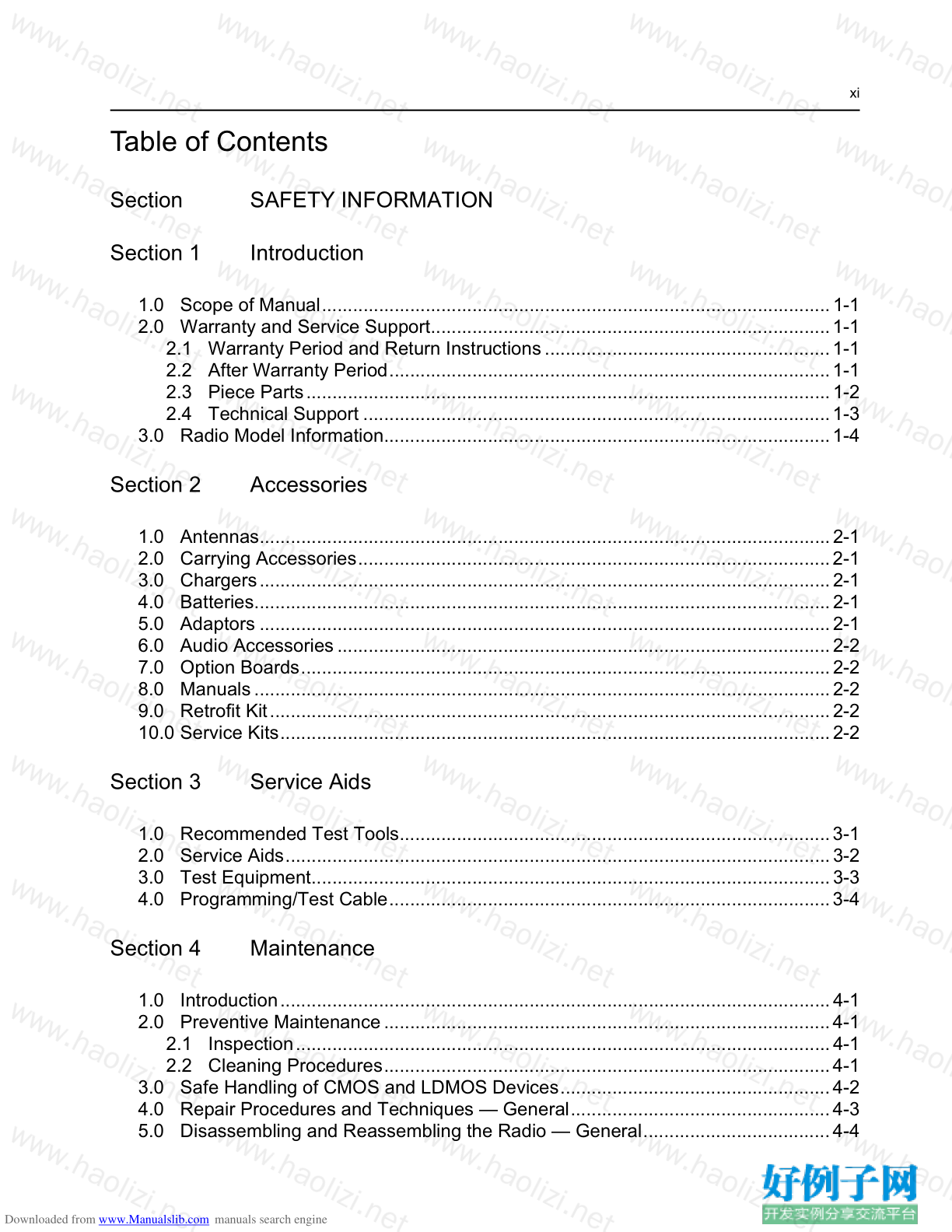
Table of Contents
Section SAFETY INFORMATION
Section 1 Introduction
1.0 Scope of Manual..................................................................................................1-1
2.0 Warranty and Service Support.............................................................................1-1
2.1 Warranty Period and Return Instructions.......................................................1-1
2.2 After Warranty Period.....................................................................................1-1
2.3 Piece Parts.....................................................................................................1-2
2.4 Technical Support ..........................................................................................1-3
3.0 Radio Model Information......................................................................................1-4
Section 2 Accessories
1.0 Antennas..............................................................................................................2-1
2.0 Carrying Accessories...........................................................................................2-1
3.0 Chargers..............................................................................................................2-1
4.0 Batteries...............................................................................................................2-1
5.0 Adaptors ..............................................................................................................2-1
6.0 Audio Accessories...............................................................................................2-2
7.0 Option Boards......................................................................................................2-2
8.0 Manuals...............................................................................................................2-2
9.0 Retrofit Kit............................................................................................................2-2
10.0 Service Kits..........................................................................................................2-2
Section 3 Service Aids
1.0 Recommended Test Tools...................................................................................3-1
2.0 Service Aids.........................................................................................................3-2
3.0 Test Equipment....................................................................................................3-3
4.0 Programming/Test Cable.....................................................................................3-4
Section 4 Maintenance
1.0 Introduction..........................................................................................................4-1
2.0 Preventive Maintenance......................................................................................4-1
2.1 Inspection.......................................................................................................4-1
2.2 Cleaning Procedures......................................................................................4-1
3.0 Safe Handling of CMOS and LDMOS Devices....................................................4-2
4.0 Repair Procedures and Techniques — General..................................................4-3
5.0 Disassembling and Reassembling the Radio — General....................................4-4
Downloaded from www.Manualslib.com manuals search engine
xii
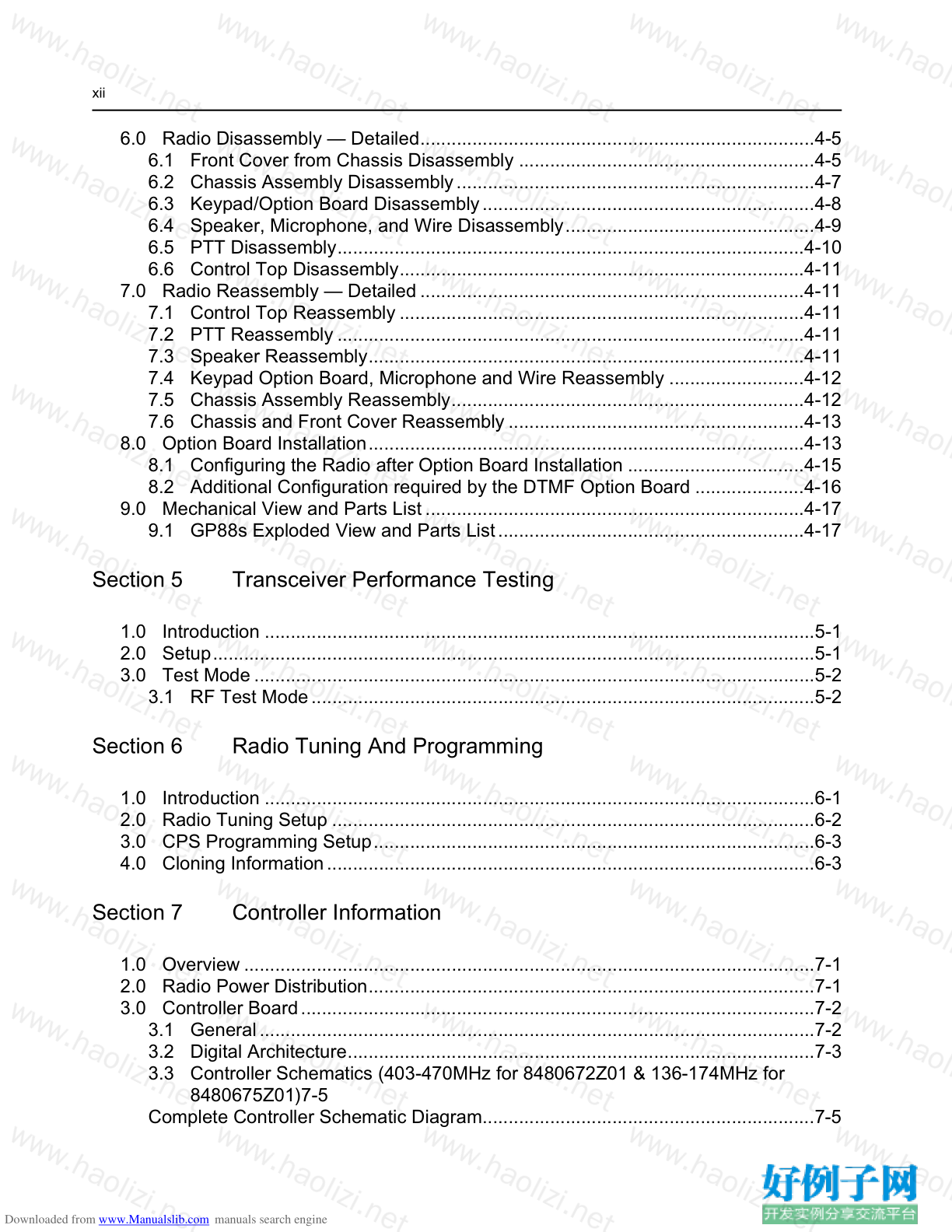
6.0 Radio Disassembly — Detailed............................................................................4-5
6.1 Front Cover from Chassis Disassembly .........................................................4-5
6.2 Chassis Assembly Disassembly.....................................................................4-7
6.3 Keypad/Option Board Disassembly................................................................4-8
6.4 Speaker, Microphone, and Wire Disassembly................................................4-9
6.5 PTT Disassembly..........................................................................................4-10
6.6 Control Top Disassembly..............................................................................4-11
7.0 Radio Reassembly — Detailed ..........................................................................4-11
7.1 Control Top Reassembly ..............................................................................4-11
7.2 PTT Reassembly ..........................................................................................4-11
7.3 Speaker Reassembly....................................................................................4-11
7.4 Keypad Option Board, Microphone and Wire Reassembly ..........................4-12
7.5 Chassis Assembly Reassembly....................................................................4-12
7.6 Chassis and Front Cover Reassembly .........................................................4-13
8.0 Option Board Installation....................................................................................4-13
8.1 Configuring the Radio after Option Board Installation ..................................4-15
8.2 Additional Configuration required by the DTMF Option Board .....................4-16
9.0 Mechanical View and Parts List.........................................................................4-17
9.1 GP88s Exploded View and Parts List...........................................................4-17
Section 5 Transceiver Performance Testing
1.0 Introduction ..........................................................................................................5-1
2.0 Setup....................................................................................................................5-1
3.0 Test Mode ............................................................................................................5-2
3.1 RF Test Mode.................................................................................................5-2
Section 6 Radio Tuning And Programming
1.0 Introduction ..........................................................................................................6-1
2.0 Radio Tuning Setup .............................................................................................6-2
3.0 CPS Programming Setup.....................................................................................6-3
4.0 Cloning Information..............................................................................................6-3
Section 7 Controller Information
1.0 Overview ..............................................................................................................7-1
2.0 Radio Power Distribution......................................................................................7-1
3.0 Controller Board...................................................................................................7-2
3.1 General...........................................................................................................7-2
3.2 Digital Architecture..........................................................................................7-3
3.3 Controller Schematics (403-470MHz for 8480672Z01 & 136-174MHz for
8480675Z01)7-5
Complete Controller Schematic Diagram................................................................7-5
Downloaded from www.Manualslib.com manuals search engine
xiii
Controller ASFIC/ON_OFF Schematic Diagram ....................................................7-6
Controller Micro Processor Schematic Diagram ....................................................7-7
Controller Memory Schematic Diagram .................................................................7-8
Controller Audio Power Amplifier Schematic Diagram...........................................7-9
Controller Interface Schematic Diagram ..............................................................7-10
3.4 Controller Schematics (403-470MHz for 8480672Z04, Z06 & 136-174MHz for
8480675Z03, Z04)7-11
Complete Controller Schematic Diagram.............................................................7-11
Controller ASFIC/ON_OFF Schematic Diagram ..................................................7-12
Controller Micro Processor Schematic Diagram ..................................................7-13
Controller Memory Schematic Diagram ...............................................................7-14
Controller Audio Power Amplifier Schematic Diagram.........................................7-15
Controller Interface Schematic Diagram ..............................................................7-16
Section 8 Keypad Board Information
1.0 Theory of Operation.............................................................................................8-1
2.0 Troubleshooting Chart.........................................................................................8-1
3.0 Parts List (Keypad)..............................................................................................8-2
4.0 Keypad Board And Schematic Diagram..............................................................8-3
Keypad Board Top and Bottom View (PCB No. 8485642Z01)...............................8-3
Keypad Board Schematic Diagram ........................................................................8-4
Section 9A Model Chart and Test Specifications (403-470 MHz)
1.0 Model Chart.......................................................................................................9A-1
2.0 Specifications.....................................................................................................9A-2
3.0 Transmitter.........................................................................................................9A-3
3.1 General.........................................................................................................9A-3
4.0 Receiver.............................................................................................................9A-5
4.1 Receiver Front-End......................................................................................9A-5
4.2 Receiver Back-End.......................................................................................9A-6
4.3 Automatic Gain Control Circuit.....................................................................9A-7
5.0 Frequency Generation Circuitry.........................................................................9A-8
5.1 Synthesizer...................................................................................................9A-9
5.2 VCO - Voltage Controlled Oscillator...........................................................9A-10
6.0 Notes For All Schematics and Circuit Boards..................................................9A-12
7.0 Circuit Board/Schematic Diagrams and Parts List...........................................9A-13
UHF (403-470MHz) Main Board Top Side PCB No. 8480672Z01.....................9A-13
UHF (403-470MHz) Main Board Bottom Side PCB No. 8480672Z01................9A-14
UHF Controls And Switches Schematic Diagram ..............................................9A-15
UHF Receiver Front End Schematic Diagram....................................................9A-16
UHF Receiver Back End Schematic Diagram....................................................9A-17
UHF Synthesizer Schematic Diagram................................................................9A-18
UHF Voltage Controlled Oscillator Schematic Diagram.....................................9A-19
Downloaded from www.Manualslib.com manuals search engine
xiv
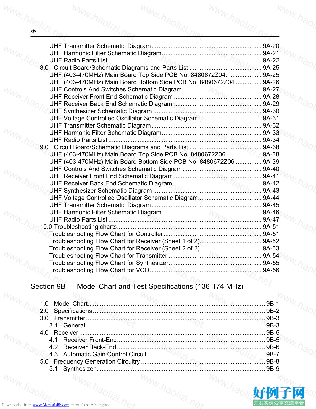
UHF Transmitter Schematic Diagram................................................................9A-20
UHF Harmonic Filter Schematic Diagram..........................................................9A-21
UHF Radio Parts List.........................................................................................9A-22
8.0 Circuit Board/Schematic Diagrams and Parts List..........................................9A-25
UHF (403-470MHz) Main Board Top Side PCB No. 8480672Z04.....................9A-25
UHF (403-470MHz) Main Board Bottom Side PCB No. 8480672Z04 ...............9A-26
UHF Controls And Switches Schematic Diagram..............................................9A-27
UHF Receiver Front End Schematic Diagram...................................................9A-28
UHF Receiver Back End Schematic Diagram....................................................9A-29
UHF Synthesizer Schematic Diagram ...............................................................9A-30
UHF Voltage Controlled Oscillator Schematic Diagram.....................................9A-31
UHF Transmitter Schematic Diagram................................................................9A-32
UHF Harmonic Filter Schematic Diagram..........................................................9A-33
UHF Radio Parts List.........................................................................................9A-34
9.0 Circuit Board/Schematic Diagrams and Parts List..........................................9A-38
UHF (403-470MHz) Main Board Top Side PCB No. 8480672Z06.....................9A-38
UHF (403-470MHz) Main Board Bottom Side PCB No. 8480672Z06 ...............9A-39
UHF Controls And Switches Schematic Diagram..............................................9A-40
UHF Receiver Front End Schematic Diagram...................................................9A-41
UHF Receiver Back End Schematic Diagram....................................................9A-42
UHF Synthesizer Schematic Diagram ...............................................................9A-43
UHF Voltage Controlled Oscillator Schematic Diagram.....................................9A-44
UHF Transmitter Schematic Diagram................................................................9A-45
UHF Harmonic Filter Schematic Diagram..........................................................9A-46
UHF Radio Parts List.........................................................................................9A-47
10.0 Troubleshooting charts....................................................................................9A-51
Troubleshooting Flow Chart for Controller.........................................................9A-51
Troubleshooting Flow Chart for Receiver (Sheet 1 of 2)....................................9A-52
Troubleshooting Flow Chart for Receiver (Sheet 2 of 2)....................................9A-53
Troubleshooting Flow Chart for Transmitter ......................................................9A-54
Troubleshooting Flow Chart for Synthesizer......................................................9A-55
Troubleshooting Flow Chart for VCO.................................................................9A-56
Section 9B Model Chart and Test Specifications (136-174 MHz)
1.0 Model Chart.......................................................................................................9B-1
2.0 Specifications....................................................................................................9B-2
3.0 Transmitter........................................................................................................9B-3
3.1 General........................................................................................................9B-3
4.0 Receiver............................................................................................................9B-5
4.1 Receiver Front-End......................................................................................9B-5
4.2 Receiver Back-End......................................................................................9B-6
4.3 Automatic Gain Control Circuit ....................................................................9B-7
5.0 Frequency Generation Circuitry ........................................................................9B-8
5.1 Synthesizer..................................................................................................9B-9
Downloaded from www.Manualslib.com manuals search engine
xv
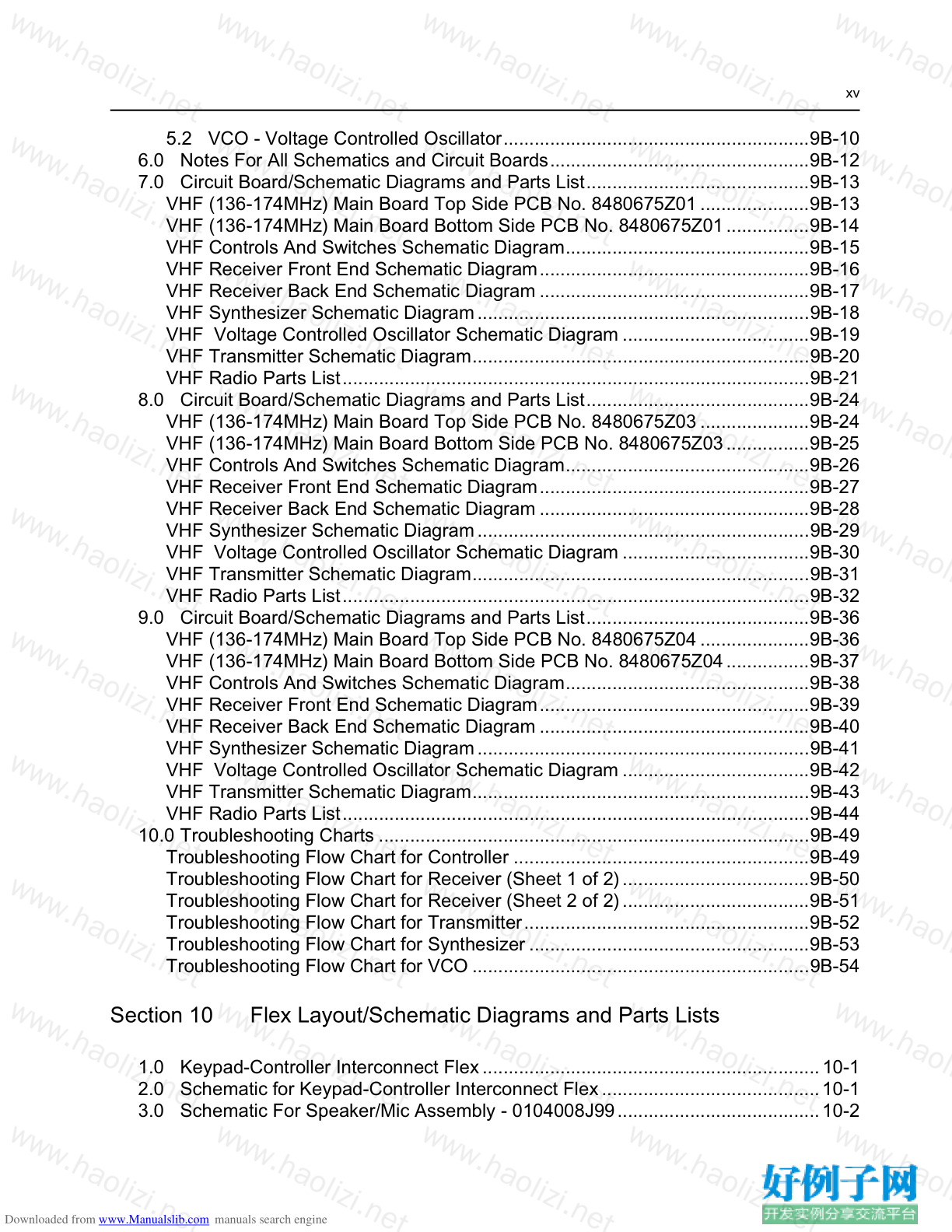
5.2 VCO - Voltage Controlled Oscillator...........................................................9B-10
6.0 Notes For All Schematics and Circuit Boards..................................................9B-12
7.0 Circuit Board/Schematic Diagrams and Parts List...........................................9B-13
VHF (136-174MHz) Main Board Top Side PCB No. 8480675Z01.....................9B-13
VHF (136-174MHz) Main Board Bottom Side PCB No. 8480675Z01................9B-14
VHF Controls And Switches Schematic Diagram...............................................9B-15
VHF Receiver Front End Schematic Diagram....................................................9B-16
VHF Receiver Back End Schematic Diagram ....................................................9B-17
VHF Synthesizer Schematic Diagram................................................................9B-18
VHF Voltage Controlled Oscillator Schematic Diagram ....................................9B-19
VHF Transmitter Schematic Diagram.................................................................9B-20
VHF Radio Parts List..........................................................................................9B-21
8.0 Circuit Board/Schematic Diagrams and Parts List...........................................9B-24
VHF (136-174MHz) Main Board Top Side PCB No. 8480675Z03.....................9B-24
VHF (136-174MHz) Main Board Bottom Side PCB No. 8480675Z03................9B-25
VHF Controls And Switches Schematic Diagram...............................................9B-26
VHF Receiver Front End Schematic Diagram....................................................9B-27
VHF Receiver Back End Schematic Diagram ....................................................9B-28
VHF Synthesizer Schematic Diagram................................................................9B-29
VHF Voltage Controlled Oscillator Schematic Diagram ....................................9B-30
VHF Transmitter Schematic Diagram.................................................................9B-31
VHF Radio Parts List..........................................................................................9B-32
9.0 Circuit Board/Schematic Diagrams and Parts List...........................................9B-36
VHF (136-174MHz) Main Board Top Side PCB No. 8480675Z04.....................9B-36
VHF (136-174MHz) Main Board Bottom Side PCB No. 8480675Z04................9B-37
VHF Controls And Switches Schematic Diagram...............................................9B-38
VHF Receiver Front End Schematic Diagram....................................................9B-39
VHF Receiver Back End Schematic Diagram ....................................................9B-40
VHF Synthesizer Schematic Diagram................................................................9B-41
VHF Voltage Controlled Oscillator Schematic Diagram ....................................9B-42
VHF Transmitter Schematic Diagram.................................................................9B-43
VHF Radio Parts List..........................................................................................9B-44
10.0 Troubleshooting Charts ...................................................................................9B-49
Troubleshooting Flow Chart for Controller .........................................................9B-49
Troubleshooting Flow Chart for Receiver (Sheet 1 of 2)....................................9B-50
Troubleshooting Flow Chart for Receiver (Sheet 2 of 2)....................................9B-51
Troubleshooting Flow Chart for Transmitter.......................................................9B-52
Troubleshooting Flow Chart for Synthesizer ......................................................9B-53
Troubleshooting Flow Chart for VCO .................................................................9B-54
Section 10 Flex Layout/Schematic Diagrams and Parts Lists
1.0 Keypad-Controller Interconnect Flex.................................................................10-1
2.0 Schematic for Keypad-Controller Interconnect Flex..........................................10-1
3.0 Schematic For Speaker/Mic Assembly - 0104008J99.......................................10-2
Downloaded from www.Manualslib.com manuals search engine
xvi
4.0 Parts List for Speaker/Mic Assembly - 0104008J99 ..........................................10-2
Glossary of Terms....................................................................................... G-1
小贴士
感谢您为本站写下的评论,您的评论对其它用户来说具有重要的参考价值,所以请认真填写。
- 类似“顶”、“沙发”之类没有营养的文字,对勤劳贡献的楼主来说是令人沮丧的反馈信息。
- 相信您也不想看到一排文字/表情墙,所以请不要反馈意义不大的重复字符,也请尽量不要纯表情的回复。
- 提问之前请再仔细看一遍楼主的说明,或许是您遗漏了。
- 请勿到处挖坑绊人、招贴广告。既占空间让人厌烦,又没人会搭理,于人于己都无利。
关于好例子网
本站旨在为广大IT学习爱好者提供一个非营利性互相学习交流分享平台。本站所有资源都可以被免费获取学习研究。本站资源来自网友分享,对搜索内容的合法性不具有预见性、识别性、控制性,仅供学习研究,请务必在下载后24小时内给予删除,不得用于其他任何用途,否则后果自负。基于互联网的特殊性,平台无法对用户传输的作品、信息、内容的权属或合法性、安全性、合规性、真实性、科学性、完整权、有效性等进行实质审查;无论平台是否已进行审查,用户均应自行承担因其传输的作品、信息、内容而可能或已经产生的侵权或权属纠纷等法律责任。本站所有资源不代表本站的观点或立场,基于网友分享,根据中国法律《信息网络传播权保护条例》第二十二与二十三条之规定,若资源存在侵权或相关问题请联系本站客服人员,点此联系我们。关于更多版权及免责申明参见 版权及免责申明


网友评论
我要评论