实例介绍
【实例简介】H8S-2472_ H8S-2463_ H8S-2462 Haredware Manual
芯片手册
【实例截图】






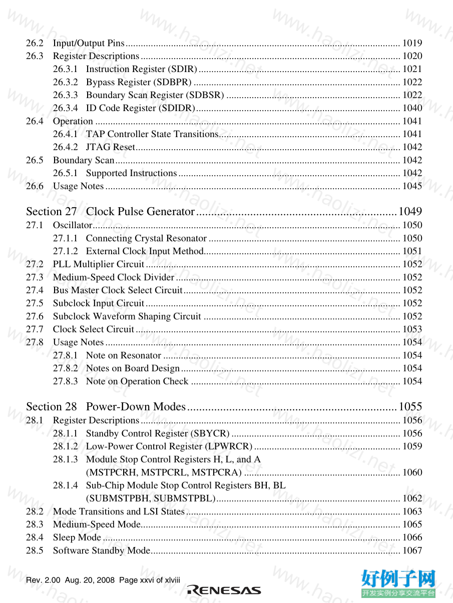
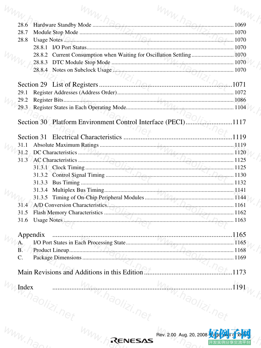
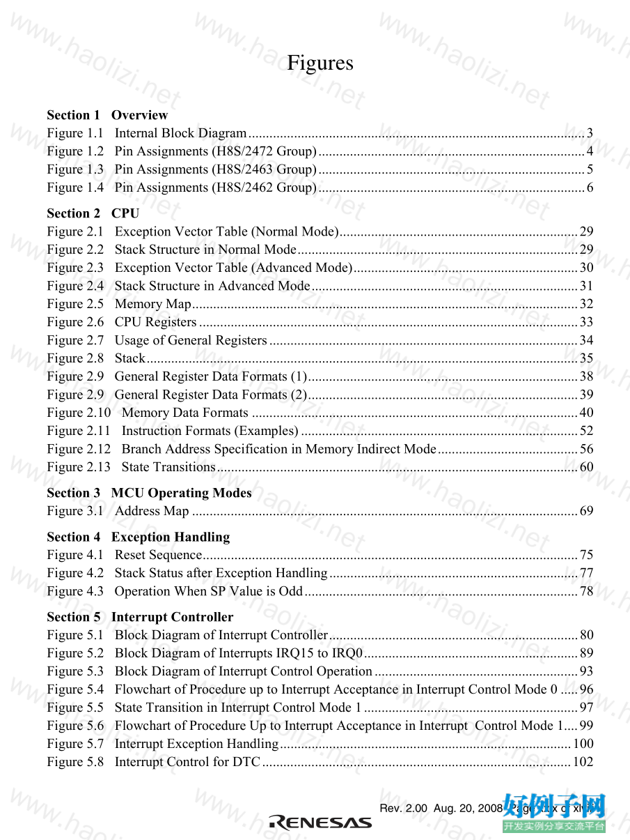
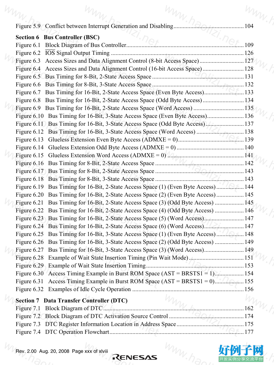
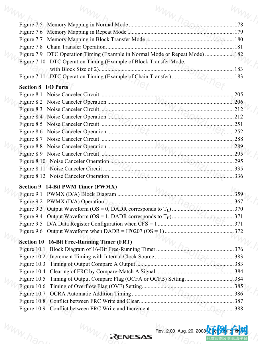
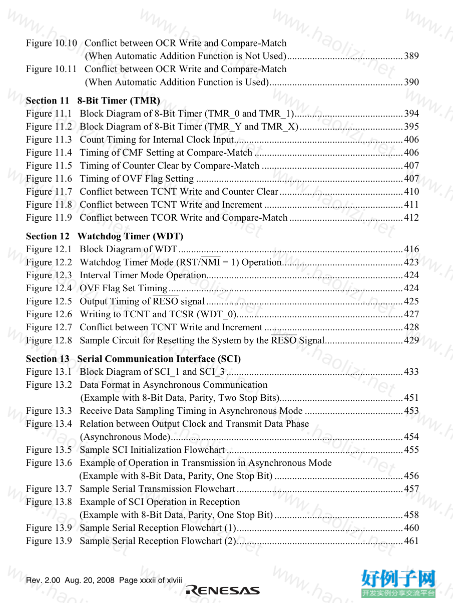
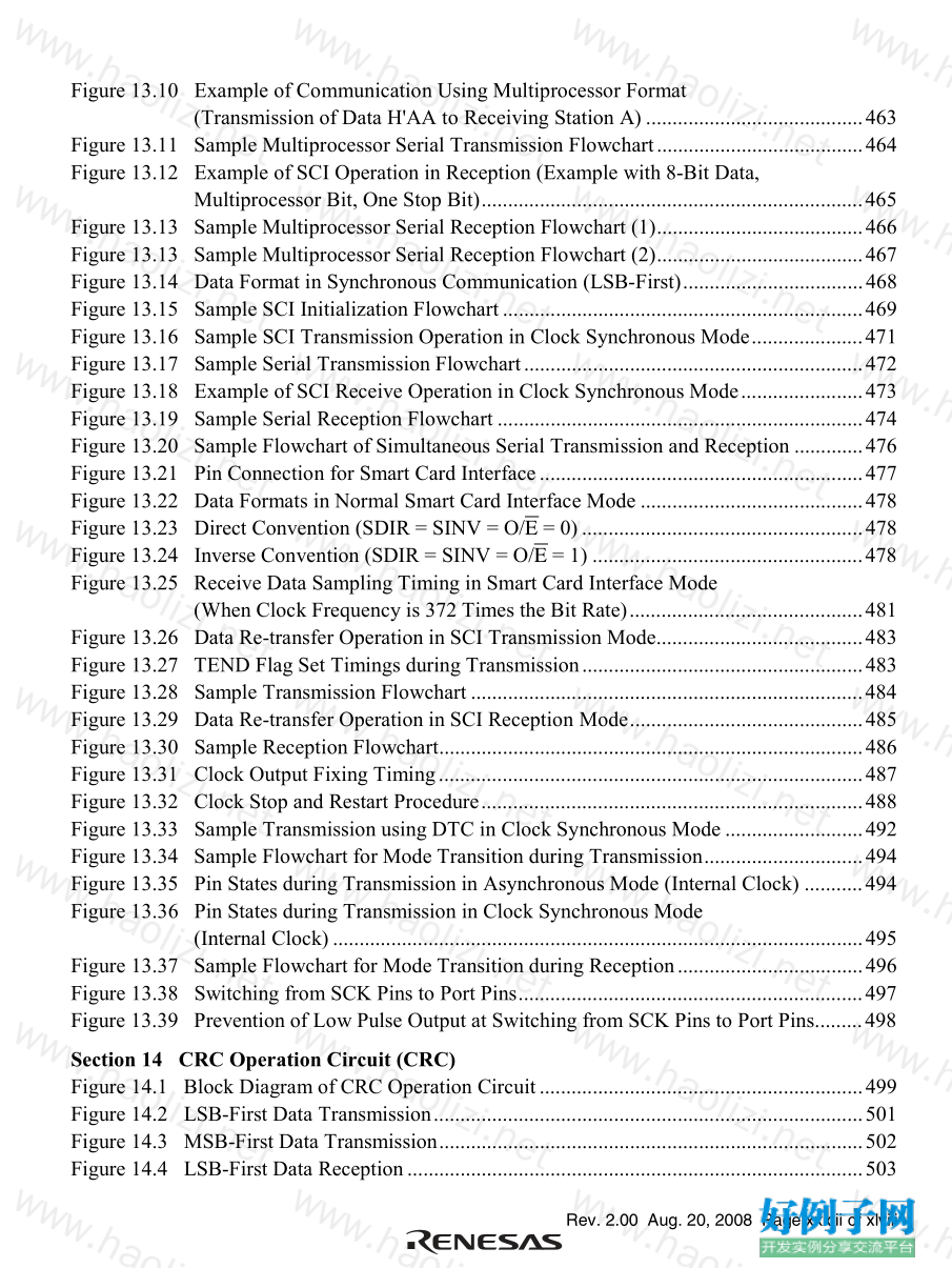

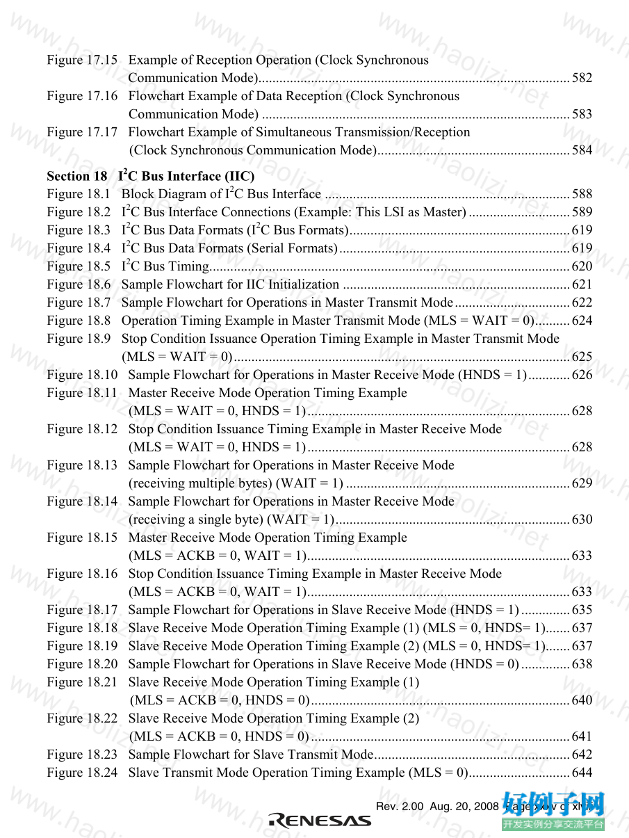
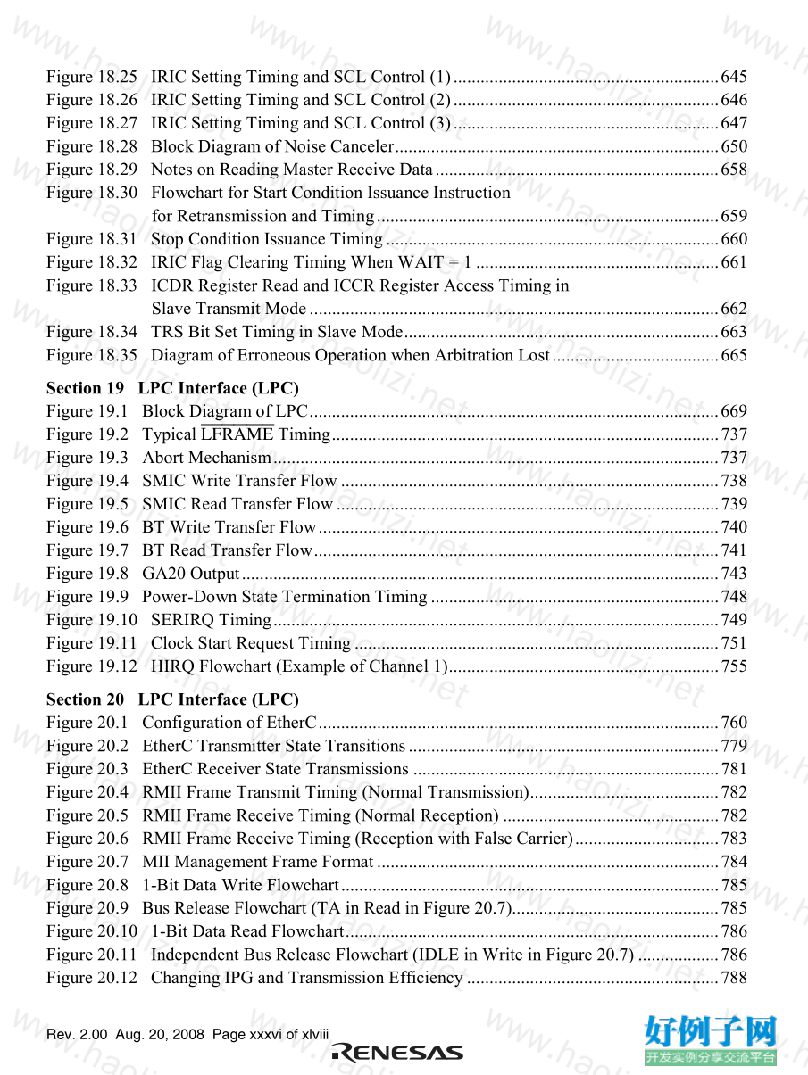


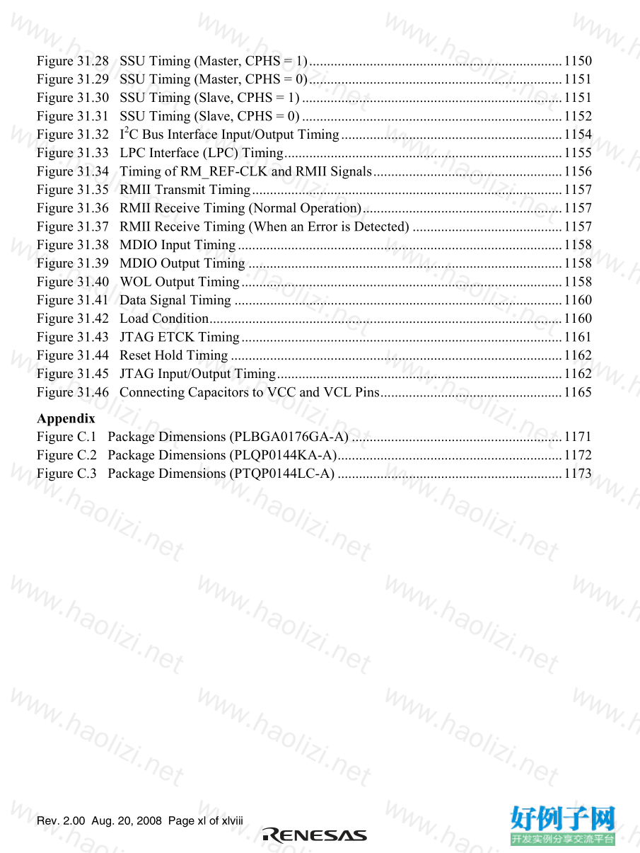
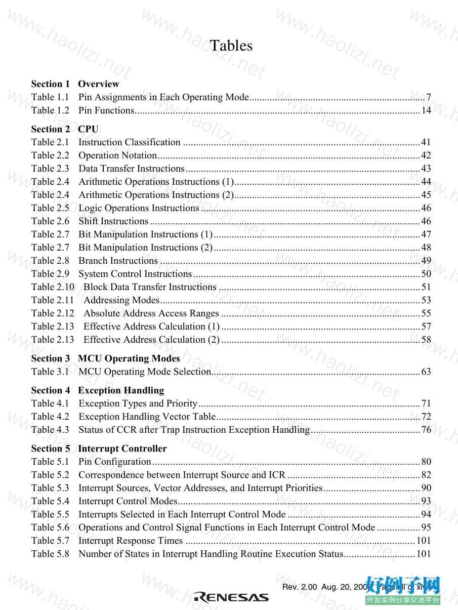
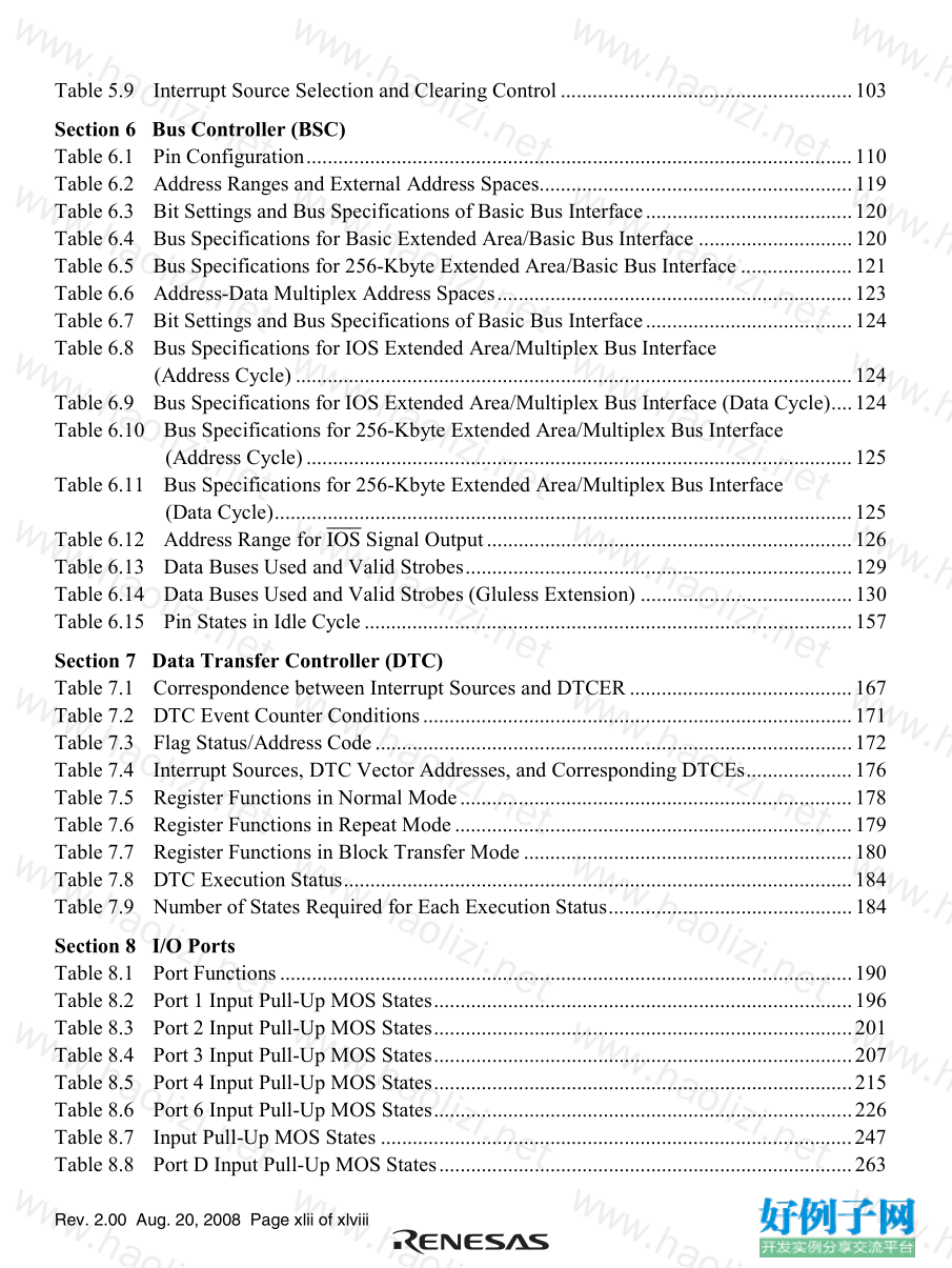

【核心代码】
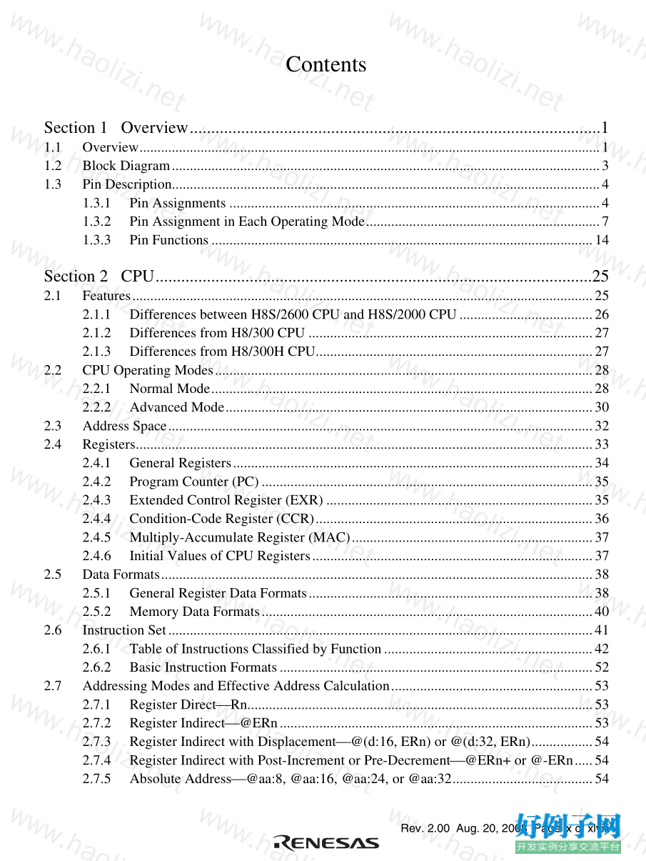
Contents
Section 1 Overview................................................................................................1
1.1 Overview................................................................................................................................1
1.2 Block Diagram.......................................................................................................................3
1.3 Pin Description.......................................................................................................................4
1.3.1 Pin Assignments .......................................................................................................4
1.3.2 Pin Assignment in Each Operating Mode.................................................................7
1.3.3 Pin Functions..........................................................................................................14
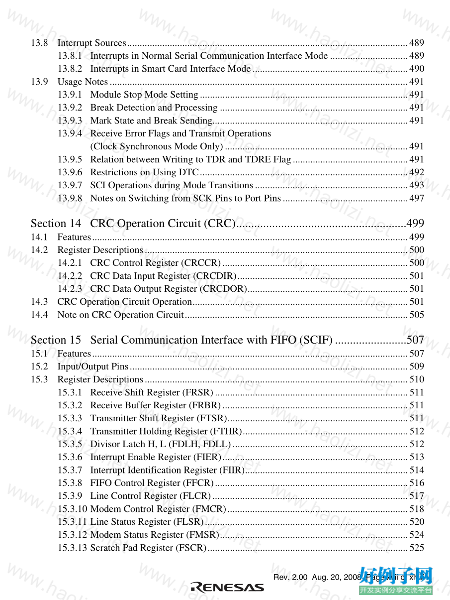
Section 2 CPU......................................................................................................25
2.1 Features................................................................................................................................25
2.1.1 Differences between H8S/2600 CPU and H8S/2000 CPU.....................................26
2.1.2 Differences from H8/300 CPU ...............................................................................27
2.1.3 Differences from H8/300H CPU.............................................................................27
2.2 CPU Operating Modes.........................................................................................................28
2.2.1 Normal Mode..........................................................................................................28
2.2.2 Advanced Mode......................................................................................................30
2.3 Address Space......................................................................................................................32
2.4 Registers...............................................................................................................................33
2.4.1 General Registers....................................................................................................34
2.4.2 Program Counter (PC)............................................................................................35
2.4.3 Extended Control Register (EXR) ..........................................................................35
2.4.4 Condition-Code Register (CCR).............................................................................36
2.4.5 Multiply-Accumulate Register (MAC)...................................................................37
2.4.6 Initial Values of CPU Registers..............................................................................37
2.5 Data Formats........................................................................................................................38
2.5.1 General Register Data Formats...............................................................................38
2.5.2 Memory Data Formats............................................................................................40
2.6 Instruction Set......................................................................................................................41
2.6.1 Table of Instructions Classified by Function..........................................................42
2.6.2 Basic Instruction Formats.......................................................................................52
2.7 Addressing Modes and Effective Address Calculation........................................................53
2.7.1 Register DirectRn................................................................................................53
2.7.2 Register Indirect@ERn.......................................................................................53
2.7.3 Register Indirect with Displacement@(d:16, ERn) or @(d:32, ERn).................54
2.7.4 Register Indirect with Post-Increment or Pre-Decrement@ERn or @-ERn.....54
2.7.5 Absolute Address@aa:8, @aa:16, @aa:24, or @aa:32.......................................54
Rev. 2.00 Aug. 20, 2008 Page x of xlviii
2.7.6 Immediate#xx:8, #xx:16, or #xx:32....................................................................55
2.7.7 Program-Counter Relative@(d:8, PC) or @(d:16, PC).......................................55
2.7.8 Memory Indirect@@aa:8...................................................................................56
2.7.9 Effective Address Calculation................................................................................57
2.8 Processing States..................................................................................................................59
2.9 Usage Note...........................................................................................................................61
2.9.1 Notes on Using the Bit Operation Instruction.........................................................61
Section 3 MCU Operating Modes.......................................................................63
3.1 Operating Mode Selection ...................................................................................................63
3.2 Register Descriptions...........................................................................................................64
3.2.1 Mode Control Register (MDCR)............................................................................64
3.2.2 System Control Register (SYSCR).........................................................................65
3.2.3 Serial Timer Control Register (STCR) ...................................................................66
3.3 Operating Mode Descriptions..............................................................................................68
3.3.1 Mode 2....................................................................................................................68
3.4 Address Map........................................................................................................................69
Section 4 Exception Handling.............................................................................71
4.1 Exception Handling Types and Priority...............................................................................71
4.2 Exception Sources and Exception Vector Table..................................................................72
4.3 Reset ....................................................................................................................................74
4.3.1 Reset Exception Handling ......................................................................................74
4.3.2 Interrupts after Reset...............................................................................................75
4.3.3 On-Chip Peripheral Modules after Reset is Cancelled............................................75
4.4 Interrupt Exception Handling...............................................................................................76
4.5 Trap Instruction Exception Handling...................................................................................76
4.6 Stack Status after Exception Handling.................................................................................77
4.7 Usage Note...........................................................................................................................78
Section 5 Interrupt Controller..............................................................................79
5.1 Features................................................................................................................................79
5.2 Input/Output Pins.................................................................................................................80
5.3 Register Descriptions...........................................................................................................81
5.3.1 Interrupt Control Registers A to D (ICRA to ICRD)..............................................81
5.3.2 Address Break Control Register (ABRKCR) .........................................................82
5.3.3 Break Address Registers A to C (BARA to BARC)...............................................83
5.3.4 IRQ Sense Control Registers (ISCR16H, ISCR16L, ISCRH, ISCRL)...................84
5.3.5 IRQ Enable Registers (IER16, IER).......................................................................86
5.3.6 IRQ Status Registers (ISR16, ISR).........................................................................87
Rev. 2.00 Aug. 20, 2008 Page xi of xlviii
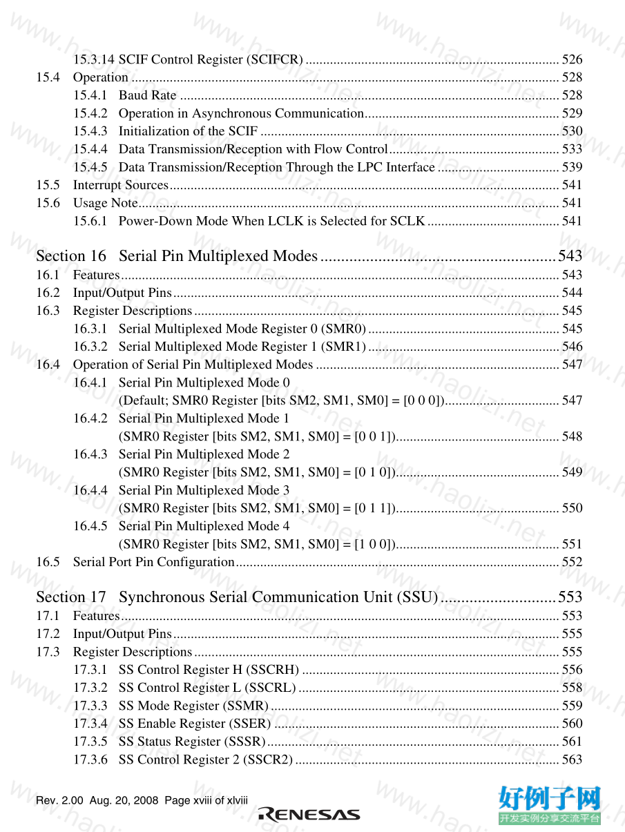
5.4 Interrupt Sources..................................................................................................................88
5.4.1 External Interrupts ..................................................................................................88
5.4.2 Internal Interrupts ...................................................................................................89
5.5 Interrupt Exception Handling Vector Table.........................................................................90
5.6 Interrupt Control Modes and Interrupt Operation................................................................93
5.6.1 Interrupt Control Mode 0........................................................................................95
5.6.2 Interrupt Control Mode 1........................................................................................97
5.6.3 Interrupt Exception Handling Sequence...............................................................100
5.6.4 Interrupt Response Times.....................................................................................101
5.6.5 DTC Activation by Interrupt.................................................................................102
5.7 Usage Notes.......................................................................................................................104
5.7.1 Conflict between Interrupt Generation and Disabling ..........................................104
5.7.2 Instructions that Disable Interrupts.......................................................................105
5.7.3 Interrupts during Execution of EEPMOV Instruction...........................................105
5.7.4 IRQ Status Registers (ISR16, ISR).......................................................................105
Section 6 Bus Controller (BSC).........................................................................107
6.1 Features..............................................................................................................................107
6.2 Input/Output Pins...............................................................................................................110
6.3 Register Descriptions.........................................................................................................111
6.3.1 Bus Control Register (BCR).................................................................................111
6.3.2 Bus Control Register 2 (BCR2)............................................................................113
6.3.3 Wait State Control Register (WSCR) ...................................................................114
6.3.4 Wait State Control Register 2 (WSCR2) ..............................................................116
6.3.5 System Control Register 2 (SYSCR2)..................................................................117
6.4 Bus Control........................................................................................................................118
6.4.1 Bus Specifications.................................................................................................118
6.4.2 Advanced Mode....................................................................................................125
6.4.3 I/O Select Signals..................................................................................................126
6.5 Bus Interface......................................................................................................................127
6.5.1 Data Size and Data Alignment..............................................................................127
6.5.2 Valid Strobes.........................................................................................................129
6.5.3 Valid Strobes (in Glueless Extension)..................................................................130
6.5.4 Basic Operation Timing in Normal Extended Mode ............................................131
6.5.5 Basic Operation Timing in Address-Data Multiplex Extended Mode..................142
6.5.6 Wait Control .........................................................................................................150
6.6 Burst ROM Interface..........................................................................................................154
6.6.1 Basic Operation Timing........................................................................................154
6.6.2 Wait Control .........................................................................................................155
6.7 Idle Cycle...........................................................................................................................156
Rev. 2.00 Aug. 20, 2008 Page xii of xlviii
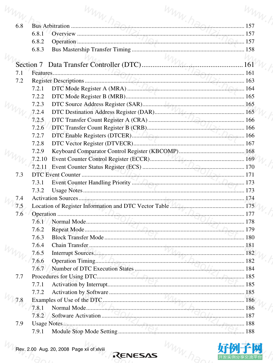
6.8 Bus Arbitration ..................................................................................................................157
6.8.1 Overview ..............................................................................................................157
6.8.2 Operation..............................................................................................................157
6.8.3 Bus Mastership Transfer Timing..........................................................................158
Section 7 Data Transfer Controller (DTC)........................................................161
7.1 Features..............................................................................................................................161
7.2 Register Descriptions.........................................................................................................163
7.2.1 DTC Mode Register A (MRA).............................................................................164
7.2.2 DTC Mode Register B (MRB)..............................................................................165
7.2.3 DTC Source Address Register (SAR)...................................................................165
7.2.4 DTC Destination Address Register (DAR)...........................................................165
7.2.5 DTC Transfer Count Register A (CRA)...............................................................166
7.2.6 DTC Transfer Count Register B (CRB)................................................................166
7.2.7 DTC Enable Registers (DTCER)..........................................................................166
7.2.8 DTC Vector Register (DTVECR).........................................................................167
7.2.9 Keyboard Comparator Control Register (KBCOMP)...........................................168
7.2.10 Event Counter Control Register (ECCR)..............................................................169
7.2.11 Event Counter Status Register (ECS)...................................................................170
7.3 DTC Event Counter...........................................................................................................171
7.3.1 Event Counter Handling Priority..........................................................................173
7.3.2 Usage Notes..........................................................................................................173
7.4 Activation Sources.............................................................................................................174
7.5 Location of Register Information and DTC Vector Table.................................................175
7.6 Operation ...........................................................................................................................177
7.6.1 Normal Mode........................................................................................................178
7.6.2 Repeat Mode.........................................................................................................179
7.6.3 Block Transfer Mode............................................................................................180
7.6.4 Chain Transfer......................................................................................................181
7.6.5 Interrupt Sources...................................................................................................182
7.6.6 Operation Timing..................................................................................................182
7.6.7 Number of DTC Execution States ........................................................................184
7.7 Procedures for Using DTC.................................................................................................185
7.7.1 Activation by Interrupt..........................................................................................185
7.7.2 Activation by Software.........................................................................................185
7.8 Examples of Use of the DTC.............................................................................................186
7.8.1 Normal Mode........................................................................................................186
7.8.2 Software Activation..............................................................................................187
7.9 Usage Notes.......................................................................................................................188
7.9.1 Module Stop Mode Setting...................................................................................188
Rev. 2.00 Aug. 20, 2008 Page xiii of xlviii
7.9.2 On-Chip RAM ......................................................................................................188
7.9.3 DTCE Bit Setting..................................................................................................188
7.9.4 DTC Activation by Interrupt Sources of SCI, IIC, or A/D Converter ..................188
Section 8 I/O Ports.............................................................................................189
8.1 I/O Ports for the H8S/2472 Group.....................................................................................189
8.1.1 Port 1.....................................................................................................................194
8.1.2 Port 2.....................................................................................................................197
8.1.3 Port 3.....................................................................................................................202
8.1.4 Port 4.....................................................................................................................208
8.1.5 Port 5.....................................................................................................................216
8.1.6 Port 6.....................................................................................................................221
8.1.7 Port 7.....................................................................................................................227
8.1.8 Port 8.....................................................................................................................231
8.1.9 Port 9.....................................................................................................................236
8.1.10 Port A....................................................................................................................240
8.1.11 Port B....................................................................................................................248
8.1.12 Port C....................................................................................................................254
8.1.13 Port D....................................................................................................................259
8.1.14 Port E....................................................................................................................264
8.1.15 Port F ....................................................................................................................268
8.2 I/O Ports for the H8S/2463 Group and the H8S/2462 Group ............................................272
8.2.1 Port 1.....................................................................................................................277
8.2.2 Port 2.....................................................................................................................280
8.2.3 Port 3.....................................................................................................................285
8.2.4 Port 4.....................................................................................................................291
8.2.5 Port 5.....................................................................................................................299
8.2.6 Port 6.....................................................................................................................304
8.2.7 Port 7.....................................................................................................................311
8.2.8 Port 8.....................................................................................................................315
8.2.9 Port 9.....................................................................................................................320
8.2.10 Port A....................................................................................................................324
8.2.11 Port B....................................................................................................................332
8.2.12 Port C....................................................................................................................338
8.2.13 Port D....................................................................................................................343
8.2.14 Port E....................................................................................................................348
8.2.15 Port F ....................................................................................................................353
8.3 Change of Peripheral Function Pins...................................................................................356
8.3.1 IRQ Sense Port Select Register 16 (ISSR16), IRQ Sense Port
Select Register (ISSR) ..........................................................................................356
Rev. 2.00 Aug. 20, 2008 Page xiv of xlviii
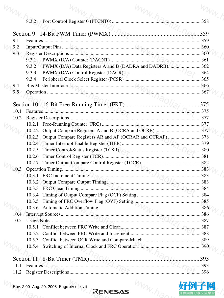
8.3.2 Port Control Register 0 (PTCNT0).......................................................................358
Section 9 14-Bit PWM Timer (PWMX) ...........................................................359
9.1 Features..............................................................................................................................359
9.2 Input/Output Pins...............................................................................................................360
9.3 Register Descriptions.........................................................................................................360
9.3.1 PWMX (D/A) Counter (DACNT)........................................................................361
9.3.2 PWMX (D/A) Data Registers A and B (DADRA and DADRB)..........................362
9.3.3 PWMX (D/A) Control Register (DACR) .............................................................364
9.3.4 Peripheral Clock Select Register (PCSR).............................................................365
9.4 Bus Master Interface..........................................................................................................366
9.5 Operation ...........................................................................................................................367
Section 10 16-Bit Free-Running Timer (FRT)..................................................375
10.1 Features..............................................................................................................................375
10.2 Register Descriptions.........................................................................................................377
10.2.1 Free-Running Counter (FRC)...............................................................................377
10.2.2 Output Compare Registers A and B (OCRA and OCRB) ....................................377
10.2.3 Output Compare Registers AR and AF (OCRAR and OCRAF)..........................378
10.2.4 Timer Interrupt Enable Register (TIER)...............................................................379
10.2.5 Timer Control/Status Register (TCSR).................................................................380
10.2.6 Timer Control Register (TCR)..............................................................................381
10.2.7 Timer Output Compare Control Register (TOCR) ...............................................382
10.3 Operation Timing...............................................................................................................383
10.3.1 FRC Increment Timing.........................................................................................383
10.3.2 Output Compare Output Timing...........................................................................383
10.3.3 FRC Clear Timing ................................................................................................384
10.3.4 Timing of Output Compare Flag (OCF) Setting...................................................384
10.3.5 Timing of FRC Overflow Flag (OVF) Setting......................................................385
10.3.6 Automatic Addition Timing..................................................................................386
10.4 Interrupt Sources................................................................................................................386
10.5 Usage Notes.......................................................................................................................387
10.5.1 Conflict between FRC Write and Clear................................................................387
10.5.2 Conflict between FRC Write and Increment.........................................................388
10.5.3 Conflict between OCR Write and Compare-Match..............................................389
10.5.4 Switching of Internal Clock and FRC Operation..................................................390
Section 11 8-Bit Timer (TMR)..........................................................................393
11.1 Features..............................................................................................................................393
11.2 Register Descriptions.........................................................................................................396
Rev. 2.00 Aug. 20, 2008 Page xv of xlviii
11.2.1 Timer Counter (TCNT).........................................................................................396
11.2.2 Time Constant Register A (TCORA)....................................................................397
11.2.3 Time Constant Register B (TCORB)....................................................................397
11.2.4 Timer Control Register (TCR)..............................................................................398
11.2.5 Timer Control/Status Register (TCSR).................................................................401
11.2.6 Timer Connection Register S (TCONRS).............................................................405
11.3 Operation Timing...............................................................................................................406
11.3.1 TCNT Count Timing.............................................................................................406
11.3.2 Timing of CMFA and CMFB Setting at Compare-Match....................................406
11.3.3 Timing of Counter Clear at Compare-Match........................................................407
11.3.4 Timing of Overflow Flag (OVF) Setting..............................................................407
11.4 TMR_0 and TMR_1 Cascaded Connection.......................................................................408
11.4.1 16-Bit Count Mode...............................................................................................408
11.4.2 Compare-Match Count Mode...............................................................................408
11.5 Interrupt Sources................................................................................................................409
11.6 Usage Notes.......................................................................................................................410
11.6.1 Conflict between TCNT Write and Counter Clear................................................410
11.6.2 Conflict between TCNT Write and Increment......................................................411
11.6.3 Conflict between TCOR Write and Compare-Match............................................412
11.6.4 Switching of Internal Clocks and TCNT Operation..............................................413
11.6.5 Mode Setting with Cascaded Connection.............................................................414
Section 12 Watchdog Timer (WDT)..................................................................415
12.1 Features..............................................................................................................................415
12.2 Input/Output Pins...............................................................................................................417
12.3 Register Descriptions.........................................................................................................417
12.3.1 Timer Counter (TCNT).........................................................................................417
12.3.2 Timer Control/Status Register (TCSR).................................................................418
12.4 Operation ...........................................................................................................................422
12.4.1 Watchdog Timer Mode.........................................................................................422
12.4.2 Interval Timer Mode.............................................................................................424
12.4.3 RESO Signal Output Timing................................................................................425
12.5 Interrupt Sources................................................................................................................426
12.6 Usage Notes.......................................................................................................................427
12.6.1 Notes on Register Access......................................................................................427
12.6.2 Conflict between Timer Counter (TCNT) Write and Increment...........................428
12.6.3 Changing Values of CKS2 to CKS0 Bits..............................................................428
12.6.4 Changing Value of PSS Bit...................................................................................428
12.6.5 Switching between Watchdog Timer Mode and Interval Timer Mode.................429
12.6.6 System Reset by RESO Signal..............................................................................429
Rev. 2.00 Aug. 20, 2008 Page xvi of xlviii
Section 13 Serial Communication Interface (SCI)............................................431
13.1 Features..............................................................................................................................431
13.2 Input/Output Pins...............................................................................................................434
13.3 Register Descriptions.........................................................................................................434
13.3.1 Receive Shift Register (RSR) ...............................................................................435
13.3.2 Receive Data Register (RDR)...............................................................................435
13.3.3 Transmit Data Register (TDR)..............................................................................435
13.3.4 Transmit Shift Register (TSR)..............................................................................435
13.3.5 Serial Mode Register (SMR) ................................................................................436
13.3.6 Serial Control Register (SCR) ..............................................................................439
13.3.7 Serial Status Register (SSR) .................................................................................442
13.3.8 Smart Card Mode Register (SCMR).....................................................................446
13.3.9 Bit Rate Register (BRR).......................................................................................447
13.4 Operation in Asynchronous Mode.....................................................................................451
13.4.1 Data Transfer Format............................................................................................452
13.4.2 Receive Data Sampling Timing and Reception Margin in
Asynchronous Mode.............................................................................................453
13.4.3 Clock.....................................................................................................................454
13.4.4 SCI Initialization (Asynchronous Mode)..............................................................455
13.4.5 Serial Data Transmission (Asynchronous Mode).................................................456
13.4.6 Serial Data Reception (Asynchronous Mode) ......................................................458
13.5 Multiprocessor Communication Function..........................................................................462
13.5.1 Multiprocessor Serial Data Transmission.............................................................464
13.5.2 Multiprocessor Serial Data Reception..................................................................465
13.6 Operation in Clock Synchronous Mode.............................................................................468
13.6.1 Clock.....................................................................................................................468
13.6.2 SCI Initialization (Clock Synchronous Mode)......................................................469
13.6.3 Serial Data Transmission (Clock Synchronous Mode).........................................470
13.6.4 Serial Data Reception (Clock Synchronous Mode)..............................................473
13.6.5 Simultaneous Serial Data Transmission and Reception
(Clock Synchronous Mode)..................................................................................475
13.7 Smart Card Interface Description ......................................................................................477
13.7.1 Sample Connection...............................................................................................477
13.7.2 Data Format (Except in Block Transfer Mode)....................................................477
13.7.3 Block Transfer Mode............................................................................................479
13.7.4 Receive Data Sampling Timing and Reception Margin .......................................480
13.7.5 Initialization..........................................................................................................481
13.7.6 Serial Data Transmission (Except in Block Transfer Mode)................................482
13.7.7 Serial Data Reception (Except in Block Transfer Mode) .....................................485
13.7.8 Clock Output Control............................................................................................487
Rev. 2.00 Aug. 20, 2008 Page xvii of xlviii
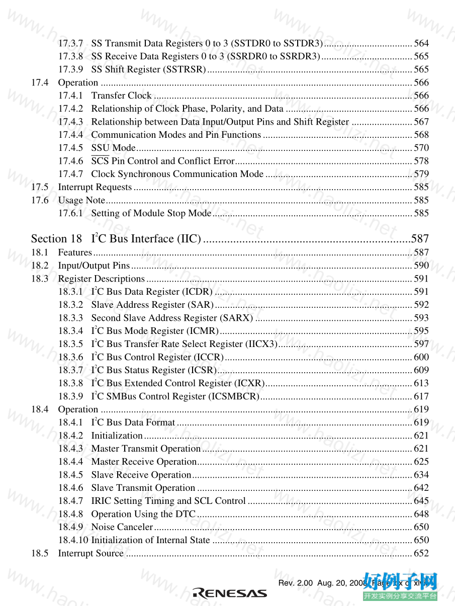
13.8 Interrupt Sources................................................................................................................489
13.8.1 Interrupts in Normal Serial Communication Interface Mode ...............................489
13.8.2 Interrupts in Smart Card Interface Mode..............................................................490
13.9 Usage Notes.......................................................................................................................491
13.9.1 Module Stop Mode Setting...................................................................................491
13.9.2 Break Detection and Processing ...........................................................................491
13.9.3 Mark State and Break Sending..............................................................................491
13.9.4 Receive Error Flags and Transmit Operations
(Clock Synchronous Mode Only).........................................................................491
13.9.5 Relation between Writing to TDR and TDRE Flag..............................................491
13.9.6 Restrictions on Using DTC...................................................................................492
13.9.7 SCI Operations during Mode Transitions.............................................................493
13.9.8 Notes on Switching from SCK Pins to Port Pins..................................................497
Section 14 CRC Operation Circuit (CRC).........................................................499
14.1 Features..............................................................................................................................499
14.2 Register Descriptions.........................................................................................................500
14.2.1 CRC Control Register (CRCCR)..........................................................................500
14.2.2 CRC Data Input Register (CRCDIR)....................................................................501
14.2.3 CRC Data Output Register (CRCDOR)................................................................501
14.3 CRC Operation Circuit Operation......................................................................................501
14.4 Note on CRC Operation Circuit.........................................................................................505
Section 15 Serial Communication Interface with FIFO (SCIF)........................507
15.1 Features..............................................................................................................................507
15.2 Input/Output Pins...............................................................................................................509
15.3 Register Descriptions.........................................................................................................510
15.3.1 Receive Shift Register (FRSR).............................................................................511
15.3.2 Receive Buffer Register (FRBR)..........................................................................511
15.3.3 Transmitter Shift Register (FTSR)........................................................................511
15.3.4 Transmitter Holding Register (FTHR)..................................................................512
15.3.5 Divisor Latch H, L (FDLH, FDLL)......................................................................512
15.3.6 Interrupt Enable Register (FIER)..........................................................................513
15.3.7 Interrupt Identification Register (FIIR).................................................................514
15.3.8 FIFO Control Register (FFCR).............................................................................516
15.3.9 Line Control Register (FLCR)..............................................................................517
15.3.10 Modem Control Register (FMCR)........................................................................518
15.3.11 Line Status Register (FLSR).................................................................................520
15.3.12 Modem Status Register (FMSR)...........................................................................524
15.3.13 Scratch Pad Register (FSCR)................................................................................525
Rev. 2.00 Aug. 20, 2008 Page xviii of xlviii
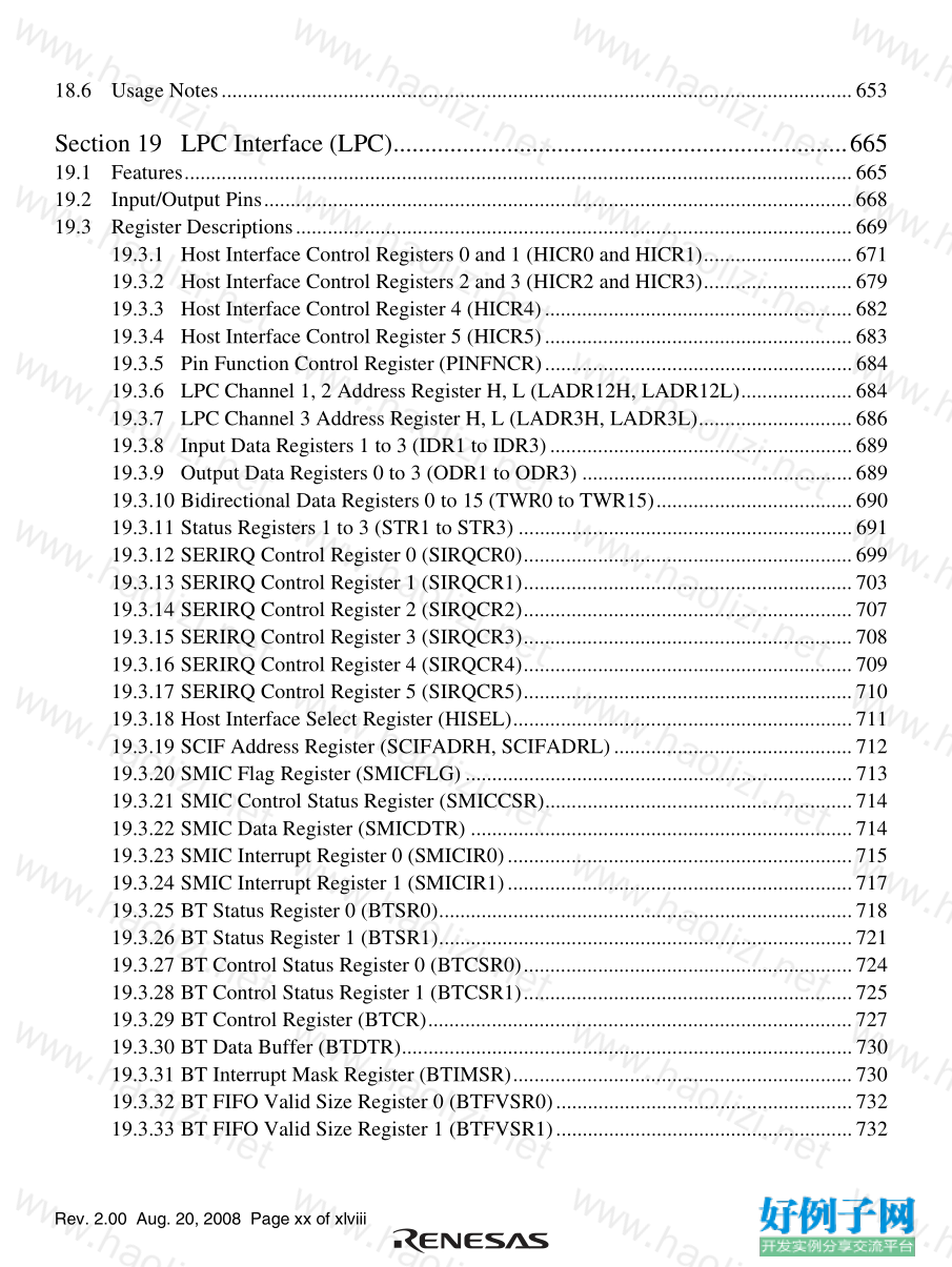
15.3.14 SCIF Control Register (SCIFCR).........................................................................526
15.4 Operation ...........................................................................................................................528
15.4.1 Baud Rate .............................................................................................................528
15.4.2 Operation in Asynchronous Communication........................................................529
15.4.3 Initialization of the SCIF ......................................................................................530
15.4.4 Data Transmission/Reception with Flow Control.................................................533
15.4.5 Data Transmission/Reception Through the LPC Interface...................................539
15.5 Interrupt Sources................................................................................................................541
15.6 Usage Note.........................................................................................................................541
15.6.1 Power-Down Mode When LCLK is Selected for SCLK......................................541
Section 16 Serial Pin Multiplexed Modes.........................................................543
16.1 Features..............................................................................................................................543
16.2 Input/Output Pins...............................................................................................................544
16.3 Register Descriptions.........................................................................................................545
16.3.1 Serial Multiplexed Mode Register 0 (SMR0).......................................................545
16.3.2 Serial Multiplexed Mode Register 1 (SMR1).......................................................546
16.4 Operation of Serial Pin Multiplexed Modes......................................................................547
16.4.1 Serial Pin Multiplexed Mode 0
(Default; SMR0 Register [bits SM2, SM1, SM0] = [0 0 0]).................................547
16.4.2 Serial Pin Multiplexed Mode 1
(SMR0 Register [bits SM2, SM1, SM0] = [0 0 1])...............................................548
16.4.3 Serial Pin Multiplexed Mode 2
(SMR0 Register [bits SM2, SM1, SM0] = [0 1 0])...............................................549
16.4.4 Serial Pin Multiplexed Mode 3
(SMR0 Register [bits SM2, SM1, SM0] = [0 1 1])...............................................550
16.4.5 Serial Pin Multiplexed Mode 4
(SMR0 Register [bits SM2, SM1, SM0] = [1 0 0])...............................................551
16.5 Serial Port Pin Configuration.............................................................................................552
Section 17 Synchronous Serial Communication Unit (SSU)............................553
17.1 Features..............................................................................................................................553
17.2 Input/Output Pins...............................................................................................................555
17.3 Register Descriptions.........................................................................................................555
17.3.1 SS Control Register H (SSCRH) ..........................................................................556
17.3.2 SS Control Register L (SSCRL)...........................................................................558
17.3.3 SS Mode Register (SSMR)...................................................................................559
17.3.4 SS Enable Register (SSER) ..................................................................................560
17.3.5 SS Status Register (SSSR)....................................................................................561
17.3.6 SS Control Register 2 (SSCR2)............................................................................563
Rev. 2.00 Aug. 20, 2008 Page xix of xlviii
17.3.7 SS Transmit Data Registers 0 to 3 (SSTDR0 to SSTDR3)...................................564
17.3.8 SS Receive Data Registers 0 to 3 (SSRDR0 to SSRDR3)....................................565
17.3.9 SS Shift Register (SSTRSR).................................................................................565
17.4 Operation ...........................................................................................................................566
17.4.1 Transfer Clock......................................................................................................566
17.4.2 Relationship of Clock Phase, Polarity, and Data ..................................................566
17.4.3 Relationship between Data Input/Output Pins and Shift Register ........................567
17.4.4 Communication Modes and Pin Functions...........................................................568
17.4.5 SSU Mode.............................................................................................................570
17.4.6 SCS Pin Control and Conflict Error......................................................................578
17.4.7 Clock Synchronous Communication Mode..........................................................579
17.5 Interrupt Requests..............................................................................................................585
17.6 Usage Note.........................................................................................................................585
17.6.1 Setting of Module Stop Mode...............................................................................585
Section 18 I
2 C Bus Interface (IIC).....................................................................587
18.1 Features..............................................................................................................................587
18.2 Input/Output Pins...............................................................................................................590
18.3 Register Descriptions.........................................................................................................591
18.3.1 I
2 C Bus Data Register (ICDR) ..............................................................................591
18.3.2 Slave Address Register (SAR)..............................................................................592
18.3.3 Second Slave Address Register (SARX) ..............................................................593
18.3.4 I
2 C Bus Mode Register (ICMR)............................................................................595
18.3.5 I
2 C Bus Transfer Rate Select Register (IICX3).....................................................597
18.3.6 I
2 C Bus Control Register (ICCR)..........................................................................600
18.3.7 I
2 C Bus Status Register (ICSR).............................................................................609
18.3.8 I
2 C Bus Extended Control Register (ICXR)..........................................................613
18.3.9 I
2 C SMBus Control Register (ICSMBCR)............................................................617
18.4 Operation ...........................................................................................................................619
18.4.1 I
2 C Bus Data Format.............................................................................................619
18.4.2 Initialization..........................................................................................................621
18.4.3 Master Transmit Operation...................................................................................621
18.4.4 Master Receive Operation.....................................................................................625
18.4.5 Slave Receive Operation.......................................................................................634
18.4.6 Slave Transmit Operation.....................................................................................642
18.4.7 IRIC Setting Timing and SCL Control.................................................................645
18.4.8 Operation Using the DTC.....................................................................................648
18.4.9 Noise Canceler......................................................................................................650
18.4.10 Initialization of Internal State ...............................................................................650
18.5 Interrupt Source .................................................................................................................652
Rev. 2.00 Aug. 20, 2008 Page xx of xlviii
18.6 Usage Notes.......................................................................................................................653
Section 19 LPC Interface (LPC)........................................................................665
19.1 Features..............................................................................................................................665
19.2 Input/Output Pins...............................................................................................................668
19.3 Register Descriptions.........................................................................................................669
19.3.1 Host Interface Control Registers 0 and 1 (HICR0 and HICR1)............................671
19.3.2 Host Interface Control Registers 2 and 3 (HICR2 and HICR3)............................679
19.3.3 Host Interface Control Register 4 (HICR4)..........................................................682
19.3.4 Host Interface Control Register 5 (HICR5)..........................................................683
19.3.5 Pin Function Control Register (PINFNCR)..........................................................684
19.3.6 LPC Channel 1, 2 Address Register H, L (LADR12H, LADR12L).....................684
19.3.7 LPC Channel 3 Address Register H, L (LADR3H, LADR3L).............................686
19.3.8 Input Data Registers 1 to 3 (IDR1 to IDR3).........................................................689
19.3.9 Output Data Registers 0 to 3 (ODR1 to ODR3) ...................................................689
19.3.10 Bidirectional Data Registers 0 to 15 (TWR0 to TWR15).....................................690
19.3.11 Status Registers 1 to 3 (STR1 to STR3) ...............................................................691
19.3.12 SERIRQ Control Register 0 (SIRQCR0)..............................................................699
19.3.13 SERIRQ Control Register 1 (SIRQCR1)..............................................................703
19.3.14 SERIRQ Control Register 2 (SIRQCR2)..............................................................707
19.3.15 SERIRQ Control Register 3 (SIRQCR3)..............................................................708
19.3.16 SERIRQ Control Register 4 (SIRQCR4)..............................................................709
19.3.17 SERIRQ Control Register 5 (SIRQCR5)..............................................................710
19.3.18 Host Interface Select Register (HISEL)................................................................711
19.3.19 SCIF Address Register (SCIFADRH, SCIFADRL).............................................712
19.3.20 SMIC Flag Register (SMICFLG) .........................................................................713
19.3.21 SMIC Control Status Register (SMICCSR)..........................................................714
19.3.22 SMIC Data Register (SMICDTR) ........................................................................714
19.3.23 SMIC Interrupt Register 0 (SMICIR0).................................................................715
19.3.24 SMIC Interrupt Register 1 (SMICIR1).................................................................717
19.3.25 BT Status Register 0 (BTSR0)..............................................................................718
19.3.26 BT Status Register 1 (BTSR1)..............................................................................721
19.3.27 BT Control Status Register 0 (BTCSR0)..............................................................724
19.3.28 BT Control Status Register 1 (BTCSR1)..............................................................725
19.3.29 BT Control Register (BTCR)................................................................................727
19.3.30 BT Data Buffer (BTDTR).....................................................................................730
19.3.31 BT Interrupt Mask Register (BTIMSR)................................................................730
19.3.32 BT FIFO Valid Size Register 0 (BTFVSR0)........................................................732
19.3.33 BT FIFO Valid Size Register 1 (BTFVSR1)........................................................732
Rev. 2.00 Aug. 20, 2008 Page xxi of xlviii
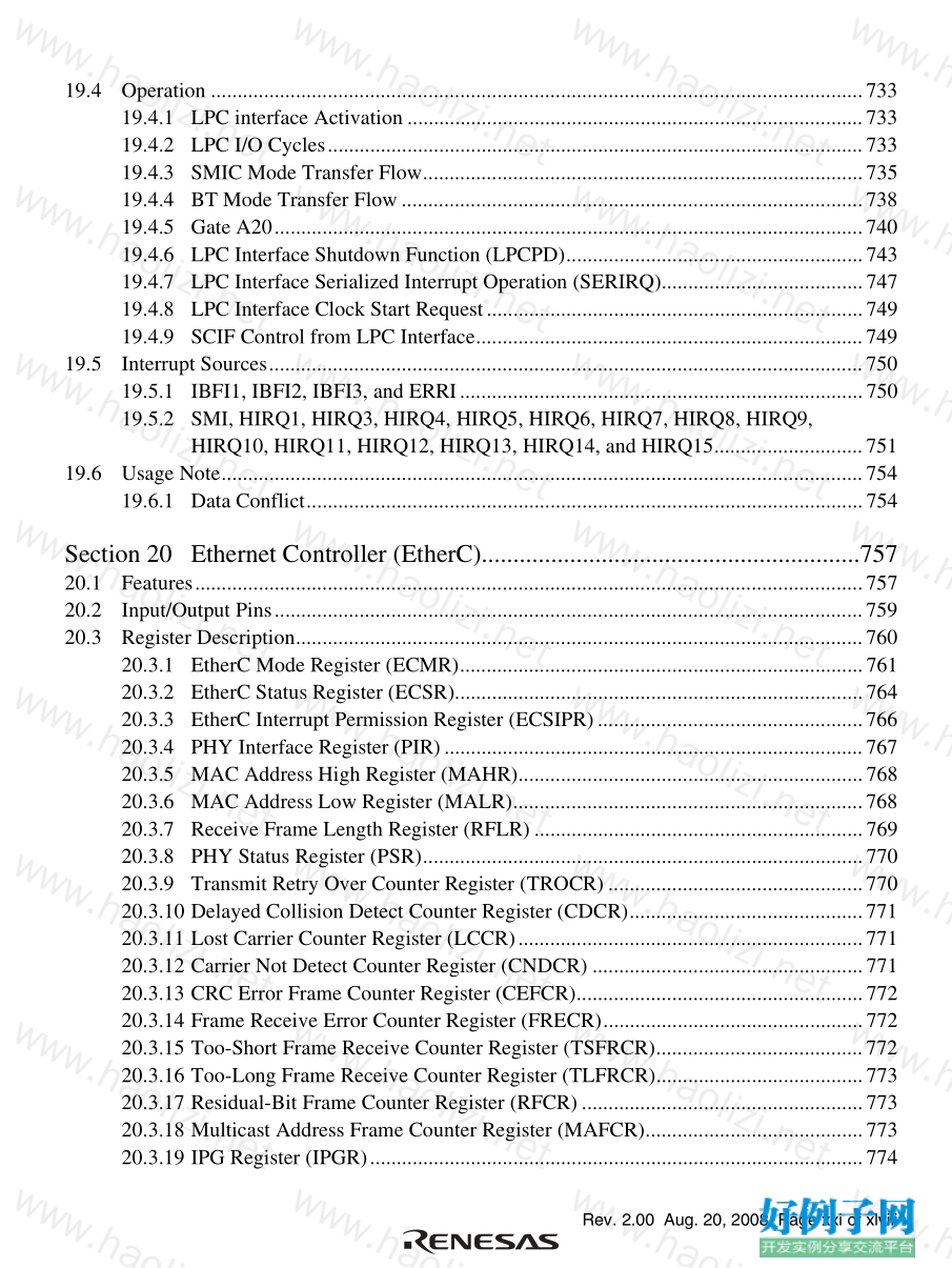
19.4 Operation ...........................................................................................................................733
19.4.1 LPC interface Activation ......................................................................................733
19.4.2 LPC I/O Cycles.....................................................................................................733
19.4.3 SMIC Mode Transfer Flow...................................................................................735
19.4.4 BT Mode Transfer Flow.......................................................................................738
19.4.5 Gate A20...............................................................................................................740
19.4.6 LPC Interface Shutdown Function (LPCPD)........................................................743
19.4.7 LPC Interface Serialized Interrupt Operation (SERIRQ)......................................747
19.4.8 LPC Interface Clock Start Request.......................................................................749
19.4.9 SCIF Control from LPC Interface.........................................................................749
19.5 Interrupt Sources................................................................................................................750
19.5.1 IBFI1, IBFI2, IBFI3, and ERRI............................................................................750
19.5.2 SMI, HIRQ1, HIRQ3, HIRQ4, HIRQ5, HIRQ6, HIRQ7, HIRQ8, HIRQ9,
HIRQ10, HIRQ11, HIRQ12, HIRQ13, HIRQ14, and HIRQ15............................751
19.6 Usage Note.........................................................................................................................754
19.6.1 Data Conflict.........................................................................................................754
Section 20 Ethernet Controller (EtherC)............................................................757
20.1 Features..............................................................................................................................757
20.2 Input/Output Pins...............................................................................................................759
20.3 Register Description...........................................................................................................760
20.3.1 EtherC Mode Register (ECMR)............................................................................761
20.3.2 EtherC Status Register (ECSR).............................................................................764
20.3.3 EtherC Interrupt Permission Register (ECSIPR)..................................................766
20.3.4 PHY Interface Register (PIR)...............................................................................767
20.3.5 MAC Address High Register (MAHR).................................................................768
20.3.6 MAC Address Low Register (MALR)..................................................................768
20.3.7 Receive Frame Length Register (RFLR) ..............................................................769
20.3.8 PHY Status Register (PSR)...................................................................................770
20.3.9 Transmit Retry Over Counter Register (TROCR) ................................................770
20.3.10 Delayed Collision Detect Counter Register (CDCR)............................................771
20.3.11 Lost Carrier Counter Register (LCCR).................................................................771
20.3.12 Carrier Not Detect Counter Register (CNDCR) ...................................................771
20.3.13 CRC Error Frame Counter Register (CEFCR)......................................................772
20.3.14 Frame Receive Error Counter Register (FRECR).................................................772
20.3.15 Too-Short Frame Receive Counter Register (TSFRCR).......................................772
20.3.16 Too-Long Frame Receive Counter Register (TLFRCR).......................................773
20.3.17 Residual-Bit Frame Counter Register (RFCR).....................................................773
20.3.18 Multicast Address Frame Counter Register (MAFCR).........................................773
20.3.19 IPG Register (IPGR).............................................................................................774
Rev. 2.00 Aug. 20, 2008 Page xxii of xlviii
20.3.20 Automatic PAUSE Frame Set Register (APR).....................................................774
20.3.21 Manual PAUSE Frame Set Register (MPR).........................................................775
20.3.22 Automatic PAUSE Frame Retransmission Count Set Register (TPAUSER).......775
20.4 Operation ...........................................................................................................................776
20.4.1 Transmission.........................................................................................................776
20.4.2 Reception..............................................................................................................779
20.4.3 RMII Frame Timing..............................................................................................780
20.4.4 Accessing MII Registers.......................................................................................782
20.4.5 Magic Packet Detection........................................................................................785
20.4.6 Operation by IPG Setting......................................................................................786
20.4.7 Flow Control.........................................................................................................786
20.5 Usage Notes.......................................................................................................................788
20.5.1 Conditions for Setting LCHNG Bit ......................................................................788
20.5.2 Flow Control Defect 1..........................................................................................788
20.5.3 Flow Control Defect 2..........................................................................................788
20.5.4 Operation Seed......................................................................................................789
Section 21 Ethernet Controller Direct Memory Access Controller
(E-DMAC).......................................................................................791
21.1 Features..............................................................................................................................791
21.2 Register Descriptions.........................................................................................................792
21.2.1 E-DMAC Mode Register (EDMR).......................................................................794
21.2.2 E-DMAC Transmit Request Register (EDTRR)...................................................795
21.2.3 E-DMAC Receive Request Register (EDRRR)....................................................796
21.2.4 Transmit Descriptor List Address Register (TDLAR)..........................................797
21.2.5 Receive Descriptor List Address Register (RDLAR)...........................................797
21.2.6 EtherC/E-DMAC Status Register (EESR)............................................................798
21.2.7 EtherC/E-DMAC Status Interrupt Permission Register (EESIPR).......................803
21.2.8 Transmit/Receive Status Copy Enable Register (TRSCER).................................806
21.2.9 Receive Missed-Frame Counter Register (RMFCR)............................................806
21.2.10 Transmit FIFO Threshold Register (TFTR)..........................................................807
21.2.11 FIFO Depth Register (FDR) .................................................................................809
21.2.12 Receiving method Control Register (RMCR).......................................................810
21.2.13 Receiving-Buffer Write Address Register (RBWAR)..........................................810
21.2.14 Receiving-Descriptor Fetch Address Register (RDFAR).....................................811
21.2.15 Transmission-Buffer Read Address Register (TBRAR).......................................811
21.2.16 Transmission-Descriptor Fetch Address Register (TDFAR)................................811
21.2.17 Flow Control FIFO Threshold Register (FCFTR)................................................812
21.2.18 Bit Rate Setting Register (ECBRR)......................................................................813
21.2.19 Transmit Interrupt Register (TRIMD) ..................................................................814
Rev. 2.00 Aug. 20, 2008 Page xxiii of xlviii
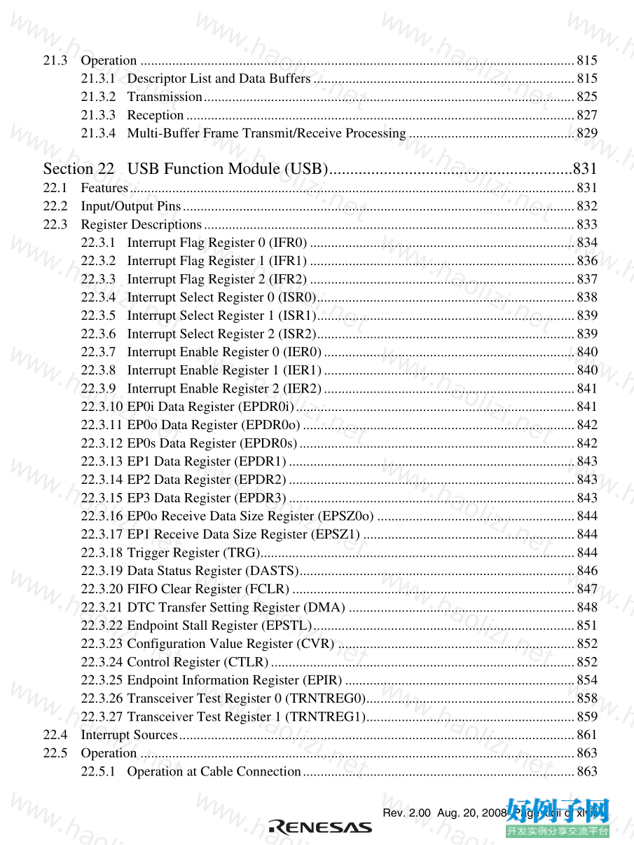
21.3 Operation ...........................................................................................................................815
21.3.1 Descriptor List and Data Buffers..........................................................................815
21.3.2 Transmission.........................................................................................................825
21.3.3 Reception..............................................................................................................827
21.3.4 Multi-Buffer Frame Transmit/Receive Processing...............................................829
Section 22 USB Function Module (USB)..........................................................831
22.1 Features..............................................................................................................................831
22.2 Input/Output Pins...............................................................................................................832
22.3 Register Descriptions.........................................................................................................833
22.3.1 Interrupt Flag Register 0 (IFR0)...........................................................................834
22.3.2 Interrupt Flag Register 1 (IFR1)...........................................................................836
22.3.3 Interrupt Flag Register 2 (IFR2)...........................................................................837
22.3.4 Interrupt Select Register 0 (ISR0).........................................................................838
22.3.5 Interrupt Select Register 1 (ISR1).........................................................................839
22.3.6 Interrupt Select Register 2 (ISR2).........................................................................839
22.3.7 Interrupt Enable Register 0 (IER0).......................................................................840
22.3.8 Interrupt Enable Register 1 (IER1).......................................................................840
22.3.9 Interrupt Enable Register 2 (IER2).......................................................................841
22.3.10 EP0i Data Register (EPDR0i)...............................................................................841
22.3.11 EP0o Data Register (EPDR0o).............................................................................842
22.3.12 EP0s Data Register (EPDR0s)..............................................................................842
22.3.13 EP1 Data Register (EPDR1).................................................................................843
22.3.14 EP2 Data Register (EPDR2).................................................................................843
22.3.15 EP3 Data Register (EPDR3).................................................................................843
22.3.16 EP0o Receive Data Size Register (EPSZ0o) ........................................................844
22.3.17 EP1 Receive Data Size Register (EPSZ1) ............................................................844
22.3.18 Trigger Register (TRG).........................................................................................844
22.3.19 Data Status Register (DASTS)..............................................................................846
22.3.20 FIFO Clear Register (FCLR)................................................................................847
22.3.21 DTC Transfer Setting Register (DMA) ................................................................848
22.3.22 Endpoint Stall Register (EPSTL)..........................................................................851
22.3.23 Configuration Value Register (CVR) ...................................................................852
22.3.24 Control Register (CTLR)......................................................................................852
22.3.25 Endpoint Information Register (EPIR).................................................................854
22.3.26 Transceiver Test Register 0 (TRNTREG0)...........................................................858
22.3.27 Transceiver Test Register 1 (TRNTREG1)...........................................................859
22.4 Interrupt Sources................................................................................................................861
22.5 Operation ...........................................................................................................................863
22.5.1 Operation at Cable Connection.............................................................................863
Rev. 2.00 Aug. 20, 2008 Page xxiv of xlviii
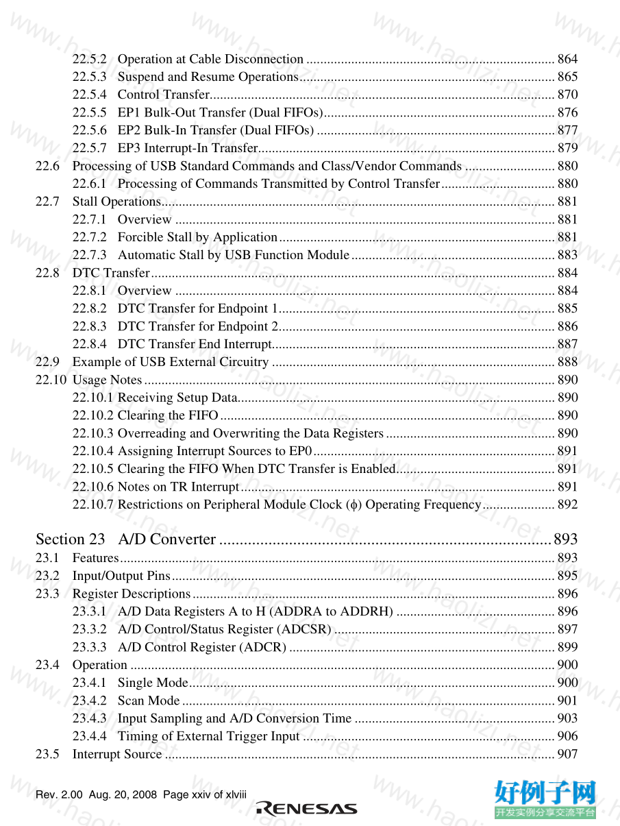
22.5.2 Operation at Cable Disconnection........................................................................864
22.5.3 Suspend and Resume Operations..........................................................................865
22.5.4 Control Transfer....................................................................................................870
22.5.5 EP1 Bulk-Out Transfer (Dual FIFOs)...................................................................876
22.5.6 EP2 Bulk-In Transfer (Dual FIFOs).....................................................................877
22.5.7 EP3 Interrupt-In Transfer......................................................................................879
22.6 Processing of USB Standard Commands and Class/Vendor Commands ..........................880
22.6.1 Processing of Commands Transmitted by Control Transfer.................................880
22.7 Stall Operations..................................................................................................................881
22.7.1 Overview ..............................................................................................................881
22.7.2 Forcible Stall by Application................................................................................881
22.7.3 Automatic Stall by USB Function Module...........................................................883
22.8 DTC Transfer.....................................................................................................................884
22.8.1 Overview ..............................................................................................................884
22.8.2 DTC Transfer for Endpoint 1................................................................................885
22.8.3 DTC Transfer for Endpoint 2................................................................................886
22.8.4 DTC Transfer End Interrupt..................................................................................887
22.9 Example of USB External Circuitry ..................................................................................888
22.10 Usage Notes.......................................................................................................................890
22.10.1 Receiving Setup Data............................................................................................890
22.10.2 Clearing the FIFO.................................................................................................890
22.10.3 Overreading and Overwriting the Data Registers.................................................890
22.10.4 Assigning Interrupt Sources to EP0......................................................................891
22.10.5 Clearing the FIFO When DTC Transfer is Enabled..............................................891
22.10.6 Notes on TR Interrupt...........................................................................................891
22.10.7 Restrictions on Peripheral Module Clock (φ) Operating Frequency.....................892
Section 23 A/D Converter.................................................................................893
23.1 Features..............................................................................................................................893
23.2 Input/Output Pins...............................................................................................................895
23.3 Register Descriptions.........................................................................................................896
23.3.1 A/D Data Registers A to H (ADDRA to ADDRH) ..............................................896
23.3.2 A/D Control/Status Register (ADCSR) ................................................................897
23.3.3 A/D Control Register (ADCR).............................................................................899
23.4 Operation ...........................................................................................................................900
23.4.1 Single Mode..........................................................................................................900
23.4.2 Scan Mode............................................................................................................901
23.4.3 Input Sampling and A/D Conversion Time ..........................................................903
23.4.4 Timing of External Trigger Input .........................................................................906
23.5 Interrupt Source.................................................................................................................907
Rev. 2.00 Aug. 20, 2008 Page xxv of xlviii
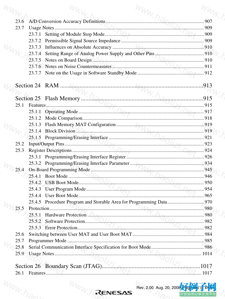
23.6 A/D Conversion Accuracy Definitions..............................................................................907
23.7 Usage Notes.......................................................................................................................909
23.7.1 Setting of Module Stop Mode...............................................................................909
23.7.2 Permissible Signal Source Impedance..................................................................909
23.7.3 Influences on Absolute Accuracy.........................................................................910
23.7.4 Setting Range of Analog Power Supply and Other Pins.......................................910
23.7.5 Notes on Board Design.........................................................................................910
23.7.6 Notes on Noise Countermeasures.........................................................................911
23.7.7 Note on the Usage in Software Standby Mode.....................................................912
Section 24 RAM ................................................................................................913
Section 25 Flash Memory..................................................................................915
25.1 Features..............................................................................................................................915
25.1.1 Operating Mode....................................................................................................917
25.1.2 Mode Comparison.................................................................................................918
25.1.3 Flash Memory MAT Configuration......................................................................919
25.1.4 Block Division......................................................................................................919
25.1.5 Programming/Erasing Interface............................................................................921
25.2 Input/Output Pins...............................................................................................................923
25.3 Register Descriptions.........................................................................................................924
25.3.1 Programming/Erasing Interface Register..............................................................926
25.3.2 Programming/Erasing Interface Parameter...........................................................934
25.4 On-Board Programming Mode ..........................................................................................945
25.4.1 Boot Mode............................................................................................................946
25.4.2 USB Boot Mode....................................................................................................950
25.4.3 User Program Mode..............................................................................................954
25.4.4 User Boot Mode....................................................................................................965
25.4.5 Procedure Program and Storable Area for Programming Data.............................970
25.5 Protection...........................................................................................................................980
25.5.1 Hardware Protection.............................................................................................980
25.5.2 Software Protection...............................................................................................982
25.5.3 Error Protection.....................................................................................................982
25.6 Switching between User MAT and User Boot MAT.........................................................984
25.7 Programmer Mode.............................................................................................................985
25.8 Serial Communication Interface Specification for Boot Mode..........................................986
25.9 Usage Notes.....................................................................................................................1014
Section 26 Boundary Scan (JTAG)..................................................................1017
26.1 Features............................................................................................................................1017
Rev. 2.00 Aug. 20, 2008 Page xxvi of xlviii
26.2 Input/Output Pins.............................................................................................................1019
26.3 Register Descriptions.......................................................................................................1020
26.3.1 Instruction Register (SDIR)................................................................................1021
26.3.2 Bypass Register (SDBPR)..................................................................................1022
26.3.3 Boundary Scan Register (SDBSR) .....................................................................1022
26.3.4 ID Code Register (SDIDR).................................................................................1040
26.4 Operation .........................................................................................................................1041
26.4.1 TAP Controller State Transitions........................................................................1041
26.4.2 JTAG Reset.........................................................................................................1042
26.5 Boundary Scan.................................................................................................................1042
26.5.1 Supported Instructions........................................................................................1042
26.6 Usage Notes.....................................................................................................................1045
Section 27 Clock Pulse Generator...................................................................1049
27.1 Oscillator..........................................................................................................................1050
27.1.1 Connecting Crystal Resonator............................................................................1050
27.1.2 External Clock Input Method..............................................................................1051
27.2 PLL Multiplier Circuit.....................................................................................................1052
27.3 Medium-Speed Clock Divider.........................................................................................1052
27.4 Bus Master Clock Select Circuit......................................................................................1052
27.5 Subclock Input Circuit.....................................................................................................1052
27.6 Subclock Waveform Shaping Circuit ..............................................................................1052
27.7 Clock Select Circuit.........................................................................................................1053
27.8 Usage Notes.....................................................................................................................1054
27.8.1 Note on Resonator ..............................................................................................1054
27.8.2 Notes on Board Design.......................................................................................1054
27.8.3 Note on Operation Check ...................................................................................1054
Section 28 Power-Down Modes......................................................................1055
28.1 Register Descriptions.......................................................................................................1056
28.1.1 Standby Control Register (SBYCR)...................................................................1056
28.1.2 Low-Power Control Register (LPWRCR)..........................................................1059
28.1.3 Module Stop Control Registers H, L, and A
(MSTPCRH, MSTPCRL, MSTPCRA) ..............................................................1060
28.1.4 Sub-Chip Module Stop Control Registers BH, BL
(SUBMSTPBH, SUBMSTPBL).........................................................................1062
28.2 Mode Transitions and LSI States.....................................................................................1063
28.3 Medium-Speed Mode.......................................................................................................1065
28.4 Sleep Mode......................................................................................................................1066
28.5 Software Standby Mode...................................................................................................1067
Rev. 2.00 Aug. 20, 2008 Page xxvii of xlviii
28.6 Hardware Standby Mode .................................................................................................1069
28.7 Module Stop Mode ..........................................................................................................1070
28.8 Usage Notes.....................................................................................................................1070
28.8.1 I/O Port Status.....................................................................................................1070
28.8.2 Current Consumption when Waiting for Oscillation Settling.............................1070
28.8.3 DTC Module Stop Mode ....................................................................................1070
28.8.4 Notes on Subclock Usage ...................................................................................1070
Section 29 List of Registers.............................................................................1071
29.1 Register Addresses (Address Order)................................................................................1072
29.2 Register Bits.....................................................................................................................1086
29.3 Register States in Each Operating Mode..........................................................................1104
Section 30 Platform Environment Control Interface (PECI)...........................1117
Section 31 Electrical Characteristics ...............................................................1119
31.1 Absolute Maximum Ratings ............................................................................................1119
31.2 DC Characteristics...........................................................................................................1120
31.3 AC Characteristics...........................................................................................................1125
31.3.1 Clock Timing......................................................................................................1125
31.3.2 Control Signal Timing........................................................................................1130
31.3.3 Bus Timing .........................................................................................................1132
31.3.4 Multiplex Bus Timing.........................................................................................1141
31.3.5 Timing of On-Chip Peripheral Modules.............................................................1144
31.4 A/D Conversion Characteristics.......................................................................................1161
31.5 Flash Memory Characteristics .........................................................................................1162
31.6 Usage Notes.....................................................................................................................1163
Appendix ........................................................................................................1165
A. I/O Port States in Each Processing State..........................................................................1165
B. Product Lineup.................................................................................................................1168
C. Package Dimensions........................................................................................................1169
Main Revisions and Additions in this Edition...................................................1173
Index ........................................................................................................1191
Rev. 2.00 Aug. 20, 2008 Page xxviii of xlviii
Rev. 2.00 Aug. 20, 2008 Page xxix of xlviii
Figures
Section 1 Overview
Figure 1.1 Internal Block Diagram................................................................................................3
Figure 1.2 Pin Assignments (H8S/2472 Group)............................................................................4
Figure 1.3 Pin Assignments (H8S/2463 Group)............................................................................5
Figure 1.4 Pin Assignments (H8S/2462 Group)............................................................................6
Section 2 CPU
Figure 2.1 Exception Vector Table (Normal Mode)....................................................................29
Figure 2.2 Stack Structure in Normal Mode................................................................................29
Figure 2.3 Exception Vector Table (Advanced Mode)................................................................30
Figure 2.4 Stack Structure in Advanced Mode............................................................................31
Figure 2.5 Memory Map..............................................................................................................32
Figure 2.6 CPU Registers............................................................................................................33
Figure 2.7 Usage of General Registers........................................................................................34
Figure 2.8 Stack...........................................................................................................................35
Figure 2.9 General Register Data Formats (1).............................................................................38
Figure 2.9 General Register Data Formats (2).............................................................................39
Figure 2.10 Memory Data Formats .............................................................................................40
Figure 2.11 Instruction Formats (Examples)...............................................................................52
Figure 2.12 Branch Address Specification in Memory Indirect Mode........................................56
Figure 2.13 State Transitions.......................................................................................................60
Section 3 MCU Operating Modes
Figure 3.1 Address Map ..............................................................................................................69
Section 4 Exception Handling
Figure 4.1 Reset Sequence...........................................................................................................75
Figure 4.2 Stack Status after Exception Handling.......................................................................77
Figure 4.3 Operation When SP Value is Odd..............................................................................78
Section 5 Interrupt Controller
Figure 5.1 Block Diagram of Interrupt Controller.......................................................................80
Figure 5.2 Block Diagram of Interrupts IRQ15 to IRQ0.............................................................89
Figure 5.3 Block Diagram of Interrupt Control Operation..........................................................93
Figure 5.4 Flowchart of Procedure up to Interrupt Acceptance in Interrupt Control Mode 0 .....96
Figure 5.5 State Transition in Interrupt Control Mode 1.............................................................97
Figure 5.6 Flowchart of Procedure Up to Interrupt Acceptance in Interrupt Control Mode 1....99
Figure 5.7 Interrupt Exception Handling...................................................................................100
Figure 5.8 Interrupt Control for DTC........................................................................................102
Rev. 2.00 Aug. 20, 2008 Page xxx of xlviii
Figure 5.9 Conflict between Interrupt Generation and Disabling..............................................104
Section 6 Bus Controller (BSC)
Figure 6.1 Block Diagram of Bus Controller.............................................................................109
Figure 6.2 IOS Signal Output Timing .......................................................................................126
Figure 6.3 Access Sizes and Data Alignment Control (8-bit Access Space).............................127
Figure 6.4 Access Sizes and Data Alignment Control (16-bit Access Space)...........................128
Figure 6.5 Bus Timing for 8-Bit, 2-State Access Space............................................................131
Figure 6.6 Bus Timing for 8-Bit, 3-State Access Space............................................................132
Figure 6.7 Bus Timing for 16-Bit, 2-State Access Space (Even Byte Access)..........................133
Figure 6.8 Bus Timing for 16-Bit, 2-State Access Space (Odd Byte Access)...........................134
Figure 6.9 Bus Timing for 16-Bit, 2-State Access Space (Word Access).................................135
Figure 6.10 Bus Timing for 16-Bit, 3-State Access Space (Even Byte Access)........................136
Figure 6.11 Bus Timing for 16-Bit, 3-State Access Space (Odd Byte Access).........................137
Figure 6.12 Bus Timing for 16-Bit, 3-State Access Space (Word Access)...............................138
Figure 6.13 Glueless Extension Even Byte Access (ADMXE = 0)...........................................139
Figure 6.14 Glueless Extension Odd Byte Access (ADMXE = 0)............................................140
Figure 6.15 Glueless Extension Word Access (ADMXE = 0) ..................................................141
Figure 6.16 Bus Timing for 8-Bit, 2-State Access Space..........................................................142
Figure 6.17 Bus Timing for 8-Bit, 2-State Access Space..........................................................143
Figure 6.18 Bus Timing for 8-Bit, 3-State Access Space..........................................................143
Figure 6.19 Bus Timing for 16-Bit, 2-State Access Space (1) (Even Byte Access)..................144
Figure 6.20 Bus Timing for 16-Bit, 2-State Access Space (2) (Even Byte Access)..................145
Figure 6.21 Bus Timing for 16-Bit, 2-State Access Space (3) (Odd Byte Access) ...................145
Figure 6.22 Bus Timing for 16-Bit, 2-State Access Space (4) (Odd Byte Access) ...................146
Figure 6.23 Bus Timing for 16-Bit, 2-State Access Space (5) (Word Access)..........................147
Figure 6.24 Bus Timing for 16-Bit, 2-State Access Space (6) (Word Access)..........................147
Figure 6.25 Bus Timing for 16-Bit, 3-State Access Space (1) (Even Byte Access)..................148
Figure 6.26 Bus Timing for 16-Bit, 3-State Access Space (2) (Odd Byte Access) ...................149
Figure 6.27 Bus Timing for 16-Bit, 3-State Access Space (3) (Word Access)..........................149
Figure 6.28 Example of Wait State Insertion Timing (Pin Wait Mode)....................................151
Figure 6.29 Example of Wait State Insertion Timing................................................................153
Figure 6.30 Access Timing Example in Burst ROM Space (AST = BRSTS1 = 1)...................154
Figure 6.31 Access Timing Example in Burst ROM Space (AST = BRSTS1 = 0)...................155
Figure 6.32 Examples of Idle Cycle Operation .........................................................................156
Section 7 Data Transfer Controller (DTC)
Figure 7.1 Block Diagram of DTC............................................................................................162
Figure 7.2 Block Diagram of DTC Activation Source Control.................................................174
Figure 7.3 DTC Register Information Location in Address Space............................................175
Figure 7.4 DTC Operation Flowchart........................................................................................177
Rev. 2.00 Aug. 20, 2008 Page xxxi of xlviii
Figure 7.5 Memory Mapping in Normal Mode.........................................................................178
Figure 7.6 Memory Mapping in Repeat Mode..........................................................................179
Figure 7.7 Memory Mapping in Block Transfer Mode .............................................................180
Figure 7.8 Chain Transfer Operation.........................................................................................181
Figure 7.9 DTC Operation Timing (Example in Normal Mode or Repeat Mode) ....................182
Figure 7.10 DTC Operation Timing (Example of Block Transfer Mode,
with Block Size of 2)..............................................................................................183
Figure 7.11 DTC Operation Timing (Example of Chain Transfer)...........................................183
Section 8 I/O Ports
Figure 8.1 Noise Canceler Circuit.............................................................................................205
Figure 8.2 Noise Canceler Operation ........................................................................................206
Figure 8.3 Noise Canceler Circuit.............................................................................................212
Figure 8.4 Noise Canceler Operation ........................................................................................212
Figure 8.5 Noise Canceler Circuit.............................................................................................251
Figure 8.6 Noise Canceler Operation ........................................................................................252
Figure 8.7 Noise Canceler Circuit.............................................................................................288
Figure 8.8 Noise Canceler Operation ........................................................................................289
Figure 8.9 Noise Canceler Circuit.............................................................................................295
Figure 8.10 Noise Canceler Operation ......................................................................................295
Figure 8.11 Noise Canceler Circuit ...........................................................................................335
Figure 8.12 Noise Canceler Operation ......................................................................................336
Section 9 14-Bit PWM Timer (PWMX)
Figure 9.1 PWMX (D/A) Block Diagram .................................................................................359
Figure 9.2 PWMX (D/A) Operation..........................................................................................367
Figure 9.3 Output Waveform (OS = 0, DADR corresponds to T L )...........................................370
Figure 9.4 Output Waveform (OS = 1, DADR corresponds to T H )...........................................371
Figure 9.5 D/A Data Register Configuration when CFS = 1.....................................................371
Figure 9.6 Output Waveform when DADR = H'0207 (OS = 1)................................................372
Section 10 16-Bit Free-Running Timer (FRT)
Figure 10.1 Block Diagram of 16-Bit Free-Running Timer......................................................376
Figure 10.2 Increment Timing with Internal Clock Source.......................................................383
Figure 10.3 Timing of Output Compare A Output....................................................................383
Figure 10.4 Clearing of FRC by Compare-Match A Signal......................................................384
Figure 10.5 Timing of Output Compare Flag (OCFA or OCFB) Setting..................................384
Figure 10.6 Timing of Overflow Flag (OVF) Setting................................................................385
Figure 10.7 OCRA Automatic Addition Timing.......................................................................386
Figure 10.8 Conflict between FRC Write and Clear..................................................................387
Figure 10.9 Conflict between FRC Write and Increment..........................................................388
Rev. 2.00 Aug. 20, 2008 Page xxxii of xlviii
Figure 10.10 Conflict between OCR Write and Compare-Match
(When Automatic Addition Function is Not Used)..............................................389
Figure 10.11 Conflict between OCR Write and Compare-Match
(When Automatic Addition Function is Used).....................................................390
Section 11 8-Bit Timer (TMR)
Figure 11.1 Block Diagram of 8-Bit Timer (TMR_0 and TMR_1)...........................................394
Figure 11.2 Block Diagram of 8-Bit Timer (TMR_Y and TMR_X).........................................395
Figure 11.3 Count Timing for Internal Clock Input...................................................................406
Figure 11.4 Timing of CMF Setting at Compare-Match...........................................................406
Figure 11.5 Timing of Counter Clear by Compare-Match ........................................................407
Figure 11.6 Timing of OVF Flag Setting ..................................................................................407
Figure 11.7 Conflict between TCNT Write and Counter Clear.................................................410
Figure 11.8 Conflict between TCNT Write and Increment .......................................................411
Figure 11.9 Conflict between TCOR Write and Compare-Match.............................................412
Section 12 Watchdog Timer (WDT)
Figure 12.1 Block Diagram of WDT.........................................................................................416
Figure 12.2 Watchdog Timer Mode (RST/NMI = 1) Operation................................................423
Figure 12.3 Interval Timer Mode Operation..............................................................................424
Figure 12.4 OVF Flag Set Timing.............................................................................................424
Figure 12.5 Output Timing of RESO signal..............................................................................425
Figure 12.6 Writing to TCNT and TCSR (WDT_0)..................................................................427
Figure 12.7 Conflict between TCNT Write and Increment .......................................................428
Figure 12.8 Sample Circuit for Resetting the System by the RESO Signal...............................429
Section 13 Serial Communication Interface (SCI)
Figure 13.1 Block Diagram of SCI_1 and SCI_3......................................................................433
Figure 13.2 Data Format in Asynchronous Communication
(Example with 8-Bit Data, Parity, Two Stop Bits).................................................451
Figure 13.3 Receive Data Sampling Timing in Asynchronous Mode .......................................453
Figure 13.4 Relation between Output Clock and Transmit Data Phase
(Asynchronous Mode)............................................................................................454
Figure 13.5 Sample SCI Initialization Flowchart......................................................................455
Figure 13.6 Example of Operation in Transmission in Asynchronous Mode
(Example with 8-Bit Data, Parity, One Stop Bit)...................................................456
Figure 13.7 Sample Serial Transmission Flowchart..................................................................457
Figure 13.8 Example of SCI Operation in Reception
(Example with 8-Bit Data, Parity, One Stop Bit)...................................................458
Figure 13.9 Sample Serial Reception Flowchart (1)..................................................................460
Figure 13.9 Sample Serial Reception Flowchart (2)..................................................................461
Rev. 2.00 Aug. 20, 2008 Page xxxiii of xlviii
Figure 13.10 Example of Communication Using Multiprocessor Format
(Transmission of Data H'AA to Receiving Station A) .........................................463
Figure 13.11 Sample Multiprocessor Serial Transmission Flowchart.......................................464
Figure 13.12 Example of SCI Operation in Reception (Example with 8-Bit Data,
Multiprocessor Bit, One Stop Bit)........................................................................465
Figure 13.13 Sample Multiprocessor Serial Reception Flowchart (1).......................................466
Figure 13.13 Sample Multiprocessor Serial Reception Flowchart (2).......................................467
Figure 13.14 Data Format in Synchronous Communication (LSB-First)..................................468
Figure 13.15 Sample SCI Initialization Flowchart....................................................................469
Figure 13.16 Sample SCI Transmission Operation in Clock Synchronous Mode.....................471
Figure 13.17 Sample Serial Transmission Flowchart................................................................472
Figure 13.18 Example of SCI Receive Operation in Clock Synchronous Mode.......................473
Figure 13.19 Sample Serial Reception Flowchart .....................................................................474
Figure 13.20 Sample Flowchart of Simultaneous Serial Transmission and Reception .............476
Figure 13.21 Pin Connection for Smart Card Interface.............................................................477
Figure 13.22 Data Formats in Normal Smart Card Interface Mode ..........................................478
Figure 13.23 Direct Convention (SDIR = SINV = O/E = 0).....................................................478
Figure 13.24 Inverse Convention (SDIR = SINV = O/E = 1) ...................................................478
Figure 13.25 Receive Data Sampling Timing in Smart Card Interface Mode
(When Clock Frequency is 372 Times the Bit Rate)............................................481
Figure 13.26 Data Re-transfer Operation in SCI Transmission Mode.......................................483
Figure 13.27 TEND Flag Set Timings during Transmission.....................................................483
Figure 13.28 Sample Transmission Flowchart ..........................................................................484
Figure 13.29 Data Re-transfer Operation in SCI Reception Mode............................................485
Figure 13.30 Sample Reception Flowchart................................................................................486
Figure 13.31 Clock Output Fixing Timing................................................................................487
Figure 13.32 Clock Stop and Restart Procedure........................................................................488
Figure 13.33 Sample Transmission using DTC in Clock Synchronous Mode ..........................492
Figure 13.34 Sample Flowchart for Mode Transition during Transmission..............................494
Figure 13.35 Pin States during Transmission in Asynchronous Mode (Internal Clock) ...........494
Figure 13.36 Pin States during Transmission in Clock Synchronous Mode
(Internal Clock)....................................................................................................495
Figure 13.37 Sample Flowchart for Mode Transition during Reception...................................496
Figure 13.38 Switching from SCK Pins to Port Pins.................................................................497
Figure 13.39 Prevention of Low Pulse Output at Switching from SCK Pins to Port Pins.........498
Section 14 CRC Operation Circuit (CRC)
Figure 14.1 Block Diagram of CRC Operation Circuit.............................................................499
Figure 14.2 LSB-First Data Transmission.................................................................................501
Figure 14.3 MSB-First Data Transmission................................................................................502
Figure 14.4 LSB-First Data Reception......................................................................................503
Rev. 2.00 Aug. 20, 2008 Page xxxiv of xlviii
Figure 14.5 MSB-First Data Reception.....................................................................................504
Figure 14.6 LSB-First and MSB-First Transmit Data ...............................................................505
Section 15 Serial Communication Interface with FIFO (SCIF)
Figure 15.1 Block Diagram of SCIF..........................................................................................508
Figure 15.2 Data Format in Serial Transmission/Reception
(Example with 8-Bit Data, Parity and 2 Stop Bits)................................................529
Figure 15.3 Example of Initialization Flowchart.......................................................................530
Figure 15.4 Example of Data Transmission Flowchart .............................................................531
Figure 15.5 Example of Data Reception Flowchart...................................................................532
Figure 15.6 Example of Initialization Flowchart.......................................................................533
Figure 15.7 Example of Data Transmission/Reception Standby Flowchart..............................534
Figure 15.8 Example of Data Transmission Flowchart .............................................................535
Figure 15.9 Example of Data Transmission Suspension Flowchart ..........................................536
Figure 15.10 Example of Data Reception Flowchart.................................................................537
Figure 15.11 Example of Data Reception Suspension Flowchart..............................................538
Section 16 Serial Pin Multiplexed Modes
Figure 16.1 Serial Pin Multiplexed Mode 0...............................................................................547
Figure 16.2 Serial Pin Multiplexed Mode 1...............................................................................548
Figure 16.3 Serial Pin Multiplexed Mode 2...............................................................................549
Figure 16.4 Serial Pin Multiplexed Mode 3...............................................................................550
Figure 16.5 Serial Pin Multiplexed Mode 4...............................................................................551
Section 17 Synchronous Serial Communication Unit (SSU)
Figure 17.1 Block Diagram of SSU...........................................................................................554
Figure 17.2 Relationship of Clock Phase, Polarity, and Data....................................................566
Figure 17.3 Relationship between Data Input/Output Pins and the Shift Register....................567
Figure 17.4 Example of Initial Settings in SSU Mode ..............................................................570
Figure 17.5 Example of Transmission Operation (SSU Mode).................................................572
Figure 17.6 Flowchart Example of Data Transmission (SSU Mode)........................................573
Figure 17.7 Example of Reception Operation (SSU Mode)......................................................575
Figure 17.8 Flowchart Example of Data Reception (SSU Mode) .............................................576
Figure 17.9 Flowchart Example of Simultaneous Transmission/Reception (SSU Mode).........577
Figure 17.10 Conflict Error Detection Timing (Before Transfer) .............................................578
Figure 17.11 Conflict Error Detection Timing (After Transfer End) ........................................578
Figure 17.12 Example of Initial Settings in Clock Synchronous Communication Mode..........579
Figure 17.13 Example of Transmission Operation (Clock Synchronous
Communication Mode).........................................................................................580
Figure 17.14 Flowchart Example of Transmission Operation
(Clock Synchronous Communication Mode).......................................................581
Rev. 2.00 Aug. 20, 2008 Page xxxv of xlviii
Figure 17.15 Example of Reception Operation (Clock Synchronous
Communication Mode).........................................................................................582
Figure 17.16 Flowchart Example of Data Reception (Clock Synchronous
Communication Mode) ........................................................................................583
Figure 17.17 Flowchart Example of Simultaneous Transmission/Reception
(Clock Synchronous Communication Mode).......................................................584
Section 18 I 2 C Bus Interface (IIC)
Figure 18.1 Block Diagram of I 2 C Bus Interface ......................................................................588
Figure 18.2 I 2 C Bus Interface Connections (Example: This LSI as Master).............................589
Figure 18.3 I 2 C Bus Data Formats (I 2 C Bus Formats)...............................................................619
Figure 18.4 I 2 C Bus Data Formats (Serial Formats)..................................................................619
Figure 18.5 I 2 C Bus Timing.......................................................................................................620
Figure 18.6 Sample Flowchart for IIC Initialization .................................................................621
Figure 18.7 Sample Flowchart for Operations in Master Transmit Mode.................................622
Figure 18.8 Operation Timing Example in Master Transmit Mode (MLS = WAIT = 0)..........624
Figure 18.9 Stop Condition Issuance Operation Timing Example in Master Transmit Mode
(MLS = WAIT = 0)................................................................................................625
Figure 18.10 Sample Flowchart for Operations in Master Receive Mode (HNDS = 1)............626
Figure 18.11 Master Receive Mode Operation Timing Example
(MLS = WAIT = 0, HNDS = 1)...........................................................................628
Figure 18.12 Stop Condition Issuance Timing Example in Master Receive Mode
(MLS = WAIT = 0, HNDS = 1)...........................................................................628
Figure 18.13 Sample Flowchart for Operations in Master Receive Mode
(receiving multiple bytes) (WAIT = 1)................................................................629
Figure 18.14 Sample Flowchart for Operations in Master Receive Mode
(receiving a single byte) (WAIT = 1)...................................................................630
Figure 18.15 Master Receive Mode Operation Timing Example
(MLS = ACKB = 0, WAIT = 1)...........................................................................633
Figure 18.16 Stop Condition Issuance Timing Example in Master Receive Mode
(MLS = ACKB = 0, WAIT = 1)...........................................................................633
Figure 18.17 Sample Flowchart for Operations in Slave Receive Mode (HNDS = 1)..............635
Figure 18.18 Slave Receive Mode Operation Timing Example (1) (MLS = 0, HNDS= 1).......637
Figure 18.19 Slave Receive Mode Operation Timing Example (2) (MLS = 0, HNDS= 1).......637
Figure 18.20 Sample Flowchart for Operations in Slave Receive Mode (HNDS = 0)..............638
Figure 18.21 Slave Receive Mode Operation Timing Example (1)
(MLS = ACKB = 0, HNDS = 0)..........................................................................640
Figure 18.22 Slave Receive Mode Operation Timing Example (2)
(MLS = ACKB = 0, HNDS = 0)..........................................................................641
Figure 18.23 Sample Flowchart for Slave Transmit Mode........................................................642
Figure 18.24 Slave Transmit Mode Operation Timing Example (MLS = 0).............................644
Rev. 2.00 Aug. 20, 2008 Page xxxvi of xlviii
Figure 18.25 IRIC Setting Timing and SCL Control (1)...........................................................645
Figure 18.26 IRIC Setting Timing and SCL Control (2)...........................................................646
Figure 18.27 IRIC Setting Timing and SCL Control (3)...........................................................647
Figure 18.28 Block Diagram of Noise Canceler........................................................................650
Figure 18.29 Notes on Reading Master Receive Data...............................................................658
Figure 18.30 Flowchart for Start Condition Issuance Instruction
for Retransmission and Timing............................................................................659
Figure 18.31 Stop Condition Issuance Timing..........................................................................660
Figure 18.32 IRIC Flag Clearing Timing When WAIT = 1......................................................661
Figure 18.33 ICDR Register Read and ICCR Register Access Timing in
Slave Transmit Mode...........................................................................................662
Figure 18.34 TRS Bit Set Timing in Slave Mode......................................................................663
Figure 18.35 Diagram of Erroneous Operation when Arbitration Lost.....................................665
Section 19 LPC Interface (LPC)
Figure 19.1 Block Diagram of LPC...........................................................................................669
Figure 19.2 Typical LFRAME Timing......................................................................................737
Figure 19.3 Abort Mechanism...................................................................................................737
Figure 19.4 SMIC Write Transfer Flow ....................................................................................738
Figure 19.5 SMIC Read Transfer Flow.....................................................................................739
Figure 19.6 BT Write Transfer Flow.........................................................................................740
Figure 19.7 BT Read Transfer Flow..........................................................................................741
Figure 19.8 GA20 Output..........................................................................................................743
Figure 19.9 Power-Down State Termination Timing................................................................748
Figure 19.10 SERIRQ Timing...................................................................................................749
Figure 19.11 Clock Start Request Timing.................................................................................751
Figure 19.12 HIRQ Flowchart (Example of Channel 1)............................................................755
Section 20 LPC Interface (LPC)
Figure 20.1 Configuration of EtherC.........................................................................................760
Figure 20.2 EtherC Transmitter State Transitions.....................................................................779
Figure 20.3 EtherC Receiver State Transmissions ....................................................................781
Figure 20.4 RMII Frame Transmit Timing (Normal Transmission)..........................................782
Figure 20.5 RMII Frame Receive Timing (Normal Reception) ................................................782
Figure 20.6 RMII Frame Receive Timing (Reception with False Carrier)................................783
Figure 20.7 MII Management Frame Format............................................................................784
Figure 20.8 1-Bit Data Write Flowchart....................................................................................785
Figure 20.9 Bus Release Flowchart (TA in Read in Figure 20.7)..............................................785
Figure 20.10 1-Bit Data Read Flowchart...................................................................................786
Figure 20.11 Independent Bus Release Flowchart (IDLE in Write in Figure 20.7) ..................786
Figure 20.12 Changing IPG and Transmission Efficiency........................................................788
Rev. 2.00 Aug. 20, 2008 Page xxxvii of xlviii
Section 21 Ethernet Controller Direct Memory Access Controller (E-DMAC)
Figure 21.1 Configuration of E-DMAC, and Descriptors and Buffers......................................794
Figure 21.2 Relationship between Transmit Descriptor and Transmit Buffer...........................818
Figure 21.3 Relationship between Receive Descriptor and Receive Buffer..............................822
Figure 21.4 Sample Transmission Flowchart ............................................................................828
Figure 21.5 Sample Reception Flowchart..................................................................................830
Figure 21.6 E-DMAC Operation after Transmit Error..............................................................831
Figure 21.7 E-DMAC Operation after Receive Error................................................................832
Section 22 USB Function Module (USB)
Figure 22.1 Block Diagram of USB ..........................................................................................834
Figure 22.2 Operation at Cable Connection ..............................................................................865
Figure 22.3 Operation at Cable Disconnection..........................................................................866
Figure 22.4 Suspend Operation.................................................................................................867
Figure 22.5 Resume Operation from Up-Stream.......................................................................868
Figure 22.6 Flow of Transition to and Canceling Software Standby Mode ..............................869
Figure 22.7 Timing of Transition to and Canceling Software Standby Mode...........................870
Figure 22.8 Remote-Wakeup.....................................................................................................871
Figure 22.9 Transfer Stages in Control Transfer.......................................................................872
Figure 22.10 Setup Stage Operation..........................................................................................873
Figure 22.11 Data Stage (Control-In) Operation.......................................................................874
Figure 22.12 Data Stage (Control-Out) Operation ....................................................................875
Figure 22.13 Status Stage (Control-In) Operation.....................................................................876
Figure 22.14 Status Stage (Control-Out) Operation..................................................................877
Figure 22.15 EP1 Bulk-Out Transfer Operation........................................................................878
Figure 22.16 EP2 Bulk-In Transfer Operation ..........................................................................879
Figure 22.17 Operation of EP3 Interrupt-In Transfer................................................................881
Figure 22.18 Forcible Stall by Application ...............................................................................884
Figure 22.19 Automatic Stall by USB Function Module...........................................................885
Figure 22.20 RDFN Bit Operation for EP1...............................................................................887
Figure 22.21 PKTE Bit Operation for EP2................................................................................888
Figure 22.22 Example of Circuitry in Self-Powered Mode.......................................................891
Figure 22.23 TR Interrupt Flag Set Timing...............................................................................893
Section 23 A/D Converter
Figure 23.1 Block Diagram of the A/D Converter ....................................................................896
Figure 23.2 Example of A/D Converter Operation (When Channel 1 is
Selected in Single Mode).......................................................................................903
Figure 23.3 Example of A/D Converter Operation (When Channels AN0 to AN3 are
Selected in Scan Mode)..........................................................................................904
Figure 23.4 A/D Conversion Timing.........................................................................................906
Rev. 2.00 Aug. 20, 2008 Page xxxviii of xlviii
Figure 23.5 Timing of External Trigger Input...........................................................................908
Figure 23.6 A/D Conversion Accuracy Definitions...................................................................910
Figure 23.7 A/D Conversion Accuracy Definitions...................................................................910
Figure 23.8 Example of Analog Input Circuit...........................................................................911
Figure 23.9 Example of Analog Input Protection Circuit..........................................................913
Figure 23.10 Analog Input Pin Equivalent Circuit....................................................................914
Section 25 Flash Memory
Figure 25.1 Block Diagram of Flash Memory...........................................................................918
Figure 25.2 Mode Transition of Flash Memory.........................................................................919
Figure 25.3 Flash Memory Configuration.................................................................................921
Figure 25.4 Block Division of User MAT.................................................................................922
Figure 25.5 Overview of User Procedure Program....................................................................923
Figure 25.6 System Configuration in Boot Mode......................................................................948
Figure 25.7 Automatic-Bit-Rate Adjustment Operation of SCI ................................................949
Figure 25.8 Overview of Boot Mode State Transition Diagram................................................951
Figure 25.9 System Configuration in USB Boot Mode.............................................................952
Figure 25.10 USB Boot Mode State Transition Diagram..........................................................954
Figure 25.11 Programming/Erasing Overview Flow.................................................................956
Figure 25.12 RAM Map When Programming/Erasing is Executed ..........................................957
Figure 25.13 Programming Procedure.......................................................................................958
Figure 25.14 Erasing Procedure.................................................................................................963
Figure 25.15 Repeating Procedure of Erasing and Programming..............................................965
Figure 25.16 Procedure for Programming User MAT in User Boot Mode ...............................968
Figure 25.17 Procedure for Erasing User MAT in User Boot Mode.........................................970
Figure 25.18 Transitions to Error-Protection State....................................................................985
Figure 25.19 Switching between the User MAT and User Boot MAT......................................986
Figure 25.20 Boot Program States.............................................................................................989
Figure 25.21 Bit-Rate-Adjustment Sequence............................................................................990
Figure 25.22 Communication Protocol Format.........................................................................991
Figure 25.23 New Bit-Rate Selection Sequence......................................................................1002
Figure 25.24 Programming Sequence......................................................................................1006
Figure 25.25 Erasure Sequence ...............................................................................................1009
Section 26 Boundary Scan (JTAG)
Figure 26.1 JTAG Block Diagram...........................................................................................1020
Figure 26.2 TAP Controller State Transitions.........................................................................1043
Figure 26.3 Reset Signal Circuit Without Reset Signal Interference.......................................1047
Figure 26.4 Serial Data Input/Output (1).................................................................................1048
Figure 26.5 Serial Data Input/Output (2).................................................................................1049
Rev. 2.00 Aug. 20, 2008 Page xxxix of xlviii
Section 27 Clock Pulse Generator
Figure 27.1 Block Diagram of Clock Pulse Generator............................................................1051
Figure 27.2 Typical Connection to Crystal Resonator.............................................................1052
Figure 27.3 Equivalent Circuit of Crystal Resonator...............................................................1052
Figure 27.4 Example of External Clock Input.........................................................................1053
Figure 27.5 Note on Board Design of Oscillation Circuit Section ..........................................1056
Section 28 Power-Down Modes
Figure 28.1 Mode Transition Diagram....................................................................................1065
Figure 28.2 Medium-Speed Mode Timing..............................................................................1068
Figure 28.3 Software Standby Mode Application Example....................................................1070
Figure 28.4 Hardware Standby Mode Timing.........................................................................1071
Section 31 Electrical Characteristics
Figure 31.1 Darlington Transistor Drive Circuit (Example)....................................................1125
Figure 31.2 LED Drive Circuit (Example)..............................................................................1126
Figure 31.3 Output Load Circuit .............................................................................................1127
Figure 31.4 System Clock Timing...........................................................................................1129
Figure 31.5 Oscillation Stabilization Timing ..........................................................................1129
Figure 31.6 Oscillation Stabilization Timing (Exiting Software Standby Mode)....................1129
Figure 31.7 External Clock Input Timing................................................................................1130
Figure 31.8 Timing of External Clock Output Stabilization Delay Time................................1130
Figure 31.9 Subclock Input Timing.........................................................................................1131
Figure 31.10 Reset Input Timing.............................................................................................1132
Figure 31.11 Interrupt Input Timing........................................................................................1133
Figure 31.12 Basic Bus Timing/2-State Access ......................................................................1135
Figure 31.13 Basic Bus Timing/3-State Access ......................................................................1136
Figure 31.14 Basic Bus Timing/3-State Access with One Wait State.....................................1137
Figure 31.15 Even Byte Access (ADMXE = 0) ......................................................................1138
Figure 31.16 Odd Byte Access (ADMXE = 0)........................................................................1139
Figure 31.17 Word Access (ADMXE = 0)..............................................................................1140
Figure 31.18 Burst ROM Access Timing/2-State Access........................................................1141
Figure 31.19 Burst ROM Access Timing/1-State Access........................................................1142
Figure 31.20 Multiplex Bus Timing/Data 2-State Access.......................................................1144
Figure 31.21 Multiplex Bus Timing/Data 3-State Access.......................................................1145
Figure 31.22 I/O Port Input/Output Timing.............................................................................1149
Figure 31.23 PWMX Output Timing.......................................................................................1149
Figure 31.24 SCK Clock Input Timing ...................................................................................1149
Figure 31.25 SCI Input/Output Timing (Clock Synchronous Mode)......................................1149
Figure 31.26 A/D Converter External Trigger Input Timing...................................................1150
Figure 31.27 WDT Output Timing (RESO)............................................................................1150
Rev. 2.00 Aug. 20, 2008 Page xl of xlviii
Figure 31.28 SSU Timing (Master, CPHS = 1).......................................................................1150
Figure 31.29 SSU Timing (Master, CPHS = 0).......................................................................1151
Figure 31.30 SSU Timing (Slave, CPHS = 1).........................................................................1151
Figure 31.31 SSU Timing (Slave, CPHS = 0).........................................................................1152
Figure 31.32 I 2 C Bus Interface Input/Output Timing..............................................................1154
Figure 31.33 LPC Interface (LPC) Timing..............................................................................1155
Figure 31.34 Timing of RM_REF-CLK and RMII Signals.....................................................1156
Figure 31.35 RMII Transmit Timing.......................................................................................1157
Figure 31.36 RMII Receive Timing (Normal Operation)........................................................1157
Figure 31.37 RMII Receive Timing (When an Error is Detected) ..........................................1157
Figure 31.38 MDIO Input Timing...........................................................................................1158
Figure 31.39 MDIO Output Timing ........................................................................................1158
Figure 31.40 WOL Output Timing..........................................................................................1158
Figure 31.41 Data Signal Timing ............................................................................................1160
Figure 31.42 Load Condition...................................................................................................1160
Figure 31.43 JTAG ETCK Timing..........................................................................................1161
Figure 31.44 Reset Hold Timing.............................................................................................1162
Figure 31.45 JTAG Input/Output Timing................................................................................1162
Figure 31.46 Connecting Capacitors to VCC and VCL Pins...................................................1165
Appendix
Figure C.1 Package Dimensions (PLBGA0176GA-A) ...........................................................1171
Figure C.2 Package Dimensions (PLQP0144KA-A)...............................................................1172
Figure C.3 Package Dimensions (PTQP0144LC-A) ...............................................................1173
Rev. 2.00 Aug. 20, 2008 Page xli of xlviii
Tables
Section 1 Overview
Table 1.1 Pin Assignments in Each Operating Mode.....................................................................7
Table 1.2 Pin Functions................................................................................................................14
Section 2 CPU
Table 2.1 Instruction Classification .............................................................................................41
Table 2.2 Operation Notation.......................................................................................................42
Table 2.3 Data Transfer Instructions............................................................................................43
Table 2.4 Arithmetic Operations Instructions (1).........................................................................44
Table 2.4 Arithmetic Operations Instructions (2).........................................................................45
Table 2.5 Logic Operations Instructions......................................................................................46
Table 2.6 Shift Instructions..........................................................................................................46
Table 2.7 Bit Manipulation Instructions (1).................................................................................47
Table 2.7 Bit Manipulation Instructions (2).................................................................................48
Table 2.8 Branch Instructions ......................................................................................................49
Table 2.9 System Control Instructions.........................................................................................50
Table 2.10 Block Data Transfer Instructions ...............................................................................51
Table 2.11 Addressing Modes......................................................................................................53
Table 2.12 Absolute Address Access Ranges ..............................................................................55
Table 2.13 Effective Address Calculation (1)..............................................................................57
Table 2.13 Effective Address Calculation (2)..............................................................................58
Section 3 MCU Operating Modes
Table 3.1 MCU Operating Mode Selection..................................................................................63
Section 4 Exception Handling
Table 4.1 Exception Types and Priority.......................................................................................71
Table 4.2 Exception Handling Vector Table................................................................................72
Table 4.3 Status of CCR after Trap Instruction Exception Handling...........................................76
Section 5 Interrupt Controller
Table 5.1 Pin Configuration.........................................................................................................80
Table 5.2 Correspondence between Interrupt Source and ICR ....................................................82
Table 5.3 Interrupt Sources, Vector Addresses, and Interrupt Priorities......................................90
Table 5.4 Interrupt Control Modes...............................................................................................93
Table 5.5 Interrupts Selected in Each Interrupt Control Mode ....................................................94
Table 5.6 Operations and Control Signal Functions in Each Interrupt Control Mode.................95
Table 5.7 Interrupt Response Times ..........................................................................................101
Table 5.8 Number of States in Interrupt Handling Routine Execution Status............................101
Rev. 2.00 Aug. 20, 2008 Page xlii of xlviii
Table 5.9 Interrupt Source Selection and Clearing Control.......................................................103
Section 6 Bus Controller (BSC)
Table 6.1 Pin Configuration.......................................................................................................110
Table 6.2 Address Ranges and External Address Spaces...........................................................119
Table 6.3 Bit Settings and Bus Specifications of Basic Bus Interface.......................................120
Table 6.4 Bus Specifications for Basic Extended Area/Basic Bus Interface .............................120
Table 6.5 Bus Specifications for 256-Kbyte Extended Area/Basic Bus Interface .....................121
Table 6.6 Address-Data Multiplex Address Spaces...................................................................123
Table 6.7 Bit Settings and Bus Specifications of Basic Bus Interface.......................................124
Table 6.8 Bus Specifications for IOS Extended Area/Multiplex Bus Interface
(Address Cycle) .........................................................................................................124
Table 6.9 Bus Specifications for IOS Extended Area/Multiplex Bus Interface (Data Cycle)....124
Table 6.10 Bus Specifications for 256-Kbyte Extended Area/Multiplex Bus Interface
(Address Cycle).......................................................................................................125
Table 6.11 Bus Specifications for 256-Kbyte Extended Area/Multiplex Bus Interface
(Data Cycle).............................................................................................................125
Table 6.12 Address Range for IOS Signal Output.....................................................................126
Table 6.13 Data Buses Used and Valid Strobes.........................................................................129
Table 6.14 Data Buses Used and Valid Strobes (Gluless Extension) ........................................130
Table 6.15 Pin States in Idle Cycle............................................................................................157
Section 7 Data Transfer Controller (DTC)
Table 7.1 Correspondence between Interrupt Sources and DTCER..........................................167
Table 7.2 DTC Event Counter Conditions.................................................................................171
Table 7.3 Flag Status/Address Code..........................................................................................172
Table 7.4 Interrupt Sources, DTC Vector Addresses, and Corresponding DTCEs....................176
Table 7.5 Register Functions in Normal Mode..........................................................................178
Table 7.6 Register Functions in Repeat Mode...........................................................................179
Table 7.7 Register Functions in Block Transfer Mode..............................................................180
Table 7.8 DTC Execution Status................................................................................................184
Table 7.9 Number of States Required for Each Execution Status..............................................184
Section 8 I/O Ports
Table 8.1 Port Functions............................................................................................................190
Table 8.2 Port 1 Input Pull-Up MOS States...............................................................................196
Table 8.3 Port 2 Input Pull-Up MOS States...............................................................................201
Table 8.4 Port 3 Input Pull-Up MOS States...............................................................................207
Table 8.5 Port 4 Input Pull-Up MOS States...............................................................................215
Table 8.6 Port 6 Input Pull-Up MOS States...............................................................................226
Table 8.7 Input Pull-Up MOS States .........................................................................................247
Table 8.8 Port D Input Pull-Up MOS States..............................................................................263
Rev. 2.00 Aug. 20, 2008 Page xliii of xlviii
Table 8.9 Port Functions............................................................................................................273
Table 8.10 Port 1 Input Pull-Up MOS States.............................................................................279
Table 8.11 Port 2 Input Pull-Up MOS States.............................................................................284
Table 8.12 Port 3 Input Pull-Up MOS States.............................................................................290
Table 8.13 Port 4 Input Pull-Up MOS States.............................................................................298
Table 8.14 Port 6 Input Pull-Up MOS States.............................................................................310
Table 8.15 Input Pull-Up MOS States........................................................................................331
Table 8.16 Port D Input Pull-Up MOS States............................................................................347
Section 9 14-Bit PWM Timer (PWMX)
Table 9.1 Pin Configuration.......................................................................................................360
Table 9.2 Clock Select of PWMX_1 and PWMX_0..................................................................365
Table 9.3 Settings and Operation (Examples when φ = 34 MHz)..............................................368
Table 9.4 Locations of Additional Pulses Added to Base Pulse (When CFS = 1).....................373
Section 10 16-Bit Free-Running Timer (FRT)
Table 10.1 FRT Interrupt Sources...........................................................................................386
Table 10.2 Switching of Internal Clock and FRC Operation..................................................391
Section 11 8-Bit Timer (TMR)
Table 11.1 (1) Clock Input to TCNT and Count Condition (TMR_0).......................................399
Table 11.1 (2) Clock Input to TCNT and Count Condition (TMR_1).......................................400
Table 11.1 (3) Clock Input to TCNT and Count Condition (TMR_X, TMR_Y).......................400
Table 11.2 Registers Accessible by TMR_X/TMR_Y...............................................................405
Table 11.3 Interrupt Sources of 8-Bit Timers TMR_0, TMR_1, TMR_Y, and TMR_X...........409
Table 11.4 Switching of Internal Clocks and TCNT Operation.................................................413
Section 12 Watchdog Timer (WDT)
Table 12.1 Pin Configuration.....................................................................................................417
Table 12.2 WDT Interrupt Source..............................................................................................426
Section 13 Serial Communication Interface (SCI)
Table 13.1 Pin Configuration.....................................................................................................434
Table 13.2 Relationships between N Setting in BRR and Bit Rate B........................................447
Table 13.3 Examples of BRR Settings for Various Bit Rates (Asynchronous Mode)...............448
Table 13.4 Maximum Bit Rate for Each Frequency (Asynchronous Mode)..............................448
Table 13.5 Maximum Bit Rate with External Clock Input (Asynchronous Mode)....................448
Table 13.6 BRR Settings for Various Bit Rates (Clock Synchronous Mode)............................449
Table 13.7 Maximum Bit Rate with External Clock Input (Clock Synchronous Mode) ...........450
Table 13.8 BRR Settings for Various Bit Rates (Smart Card Interface Mode, n = 0,
s = 372) ....................................................................................................................450
Table 13.9 Maximum Bit Rate for Each Frequency (Smart Card Interface Mode, S = 372).....450
Table 13.10 Serial Transfer Formats (Asynchronous Mode).....................................................452
Rev. 2.00 Aug. 20, 2008 Page xliv of xlviii
Table 13.11 SSR Status Flags and Receive Data Handling .......................................................459
Table 13.12 SCI Interrupt Sources.............................................................................................489
Table 13.13 SCI Interrupt Sources.............................................................................................490
Section 15 Serial Communication Interface with FIFO (SCIF)
Table 15.1 Pin Configuration.....................................................................................................509
Table 15.2 Register Access........................................................................................................510
Table 15.3 Interrupt Control Function .......................................................................................515
Table 15.4 SCIF Output Setting.................................................................................................527
Table 15.5 Example of Baud Rate Settings................................................................................528
Table 15.6 Correspondence Between LPC Interface I/O Address and the SCIF Registers .......539
Table 15.7 Register States..........................................................................................................540
Table 15.8 Interrupt Sources......................................................................................................541
Table 15.9 Interrupt Source, Vector Address, and Interrupt Priority.........................................541
Section 16 Serial Pin Multiplexed Modes
Table 16.1 Pin Configuration.....................................................................................................544
Section 17 Synchronous Serial Communication Unit (SSU)
Table 17.1 Pin Configuration.....................................................................................................555
Table 17.2 Communication Modes and Pin States of SSI and SSO Pins...................................568
Table 17.3 Communication Modes and Pin States of SSCK Pin...............................................569
Table 17.4 Communication Modes and Pin States of SCS Pin..................................................569
Table 17.5 Interrupt Sources......................................................................................................585
Section 18 I 2 C Bus Interface (IIC)
Table 18.1 Pin Configuration.....................................................................................................590
Table 18.2 Transfer Format........................................................................................................594
Table 18.3 I 2 C bus Transfer Rate (1) .........................................................................................598
Table 18.3 I 2 C bus Transfer Rate (2) .........................................................................................599
Table 18.4 Flags and Transfer States (Master Mode)................................................................606
Table 18.5 Flags and Transfer States (Slave Mode)...................................................................607
Table 18.6 Output Data Hold Time............................................................................................618
Table 18.7 ISCMBCR Setting....................................................................................................618
Table 18.8 I 2 C Bus Data Format Symbols.................................................................................620
Table 18.9 Examples of Operation Using the DTC ...................................................................649
Table 18.10 IIC Interrupt Source...............................................................................................652
Table 18.11 I 2 C Bus Timing (SCL and SDA Outputs)..............................................................653
Table 18.12 Permissible SCL Rise Time (t sr ) Values.................................................................654
Table 18.13 I 2 C Bus Timing (with Maximum Influence of t Sr /t Sf ).............................................656
Section 19 LPC Interface (LPC)
Table 19.1 Pin Configuration.....................................................................................................670
Rev. 2.00 Aug. 20, 2008 Page xlv of xlviii
Table 19.2 LADR1, LADR2 Initial Values ...............................................................................686
Table 19.3 Host Register Selection............................................................................................687
Table 19.4 Slave Selection Internal Registers............................................................................687
Table 19.5 LPC I/O Cycle..........................................................................................................736
Table 19.6 GA20 Setting/Clearing Timing................................................................................742
Table 19.7 Fast Gate A20 Output Signals..................................................................................744
Table 19.8 Scope of LPC Interface Pin Shutdown.....................................................................746
Table 19.9 Scope of Initialization in Each LPC interface Mode................................................747
Table 19.10 Serialized Interrupt Transfer Cycle Frame Configuration......................................750
Table 19.11 Receive Complete Interrupts and Error Interrupt...................................................752
Table 19.12 HIRQ Setting and Clearing Conditions when LPC Channels are Used.................754
Table 19.13 HIRQ Setting and Clearing Conditions when SCIF Channels are Used................755
Table 19.14 Host Address Example...........................................................................................757
Section 20 Ethernet Controller (EtherC)
Table 20.1 Pin Configuration.....................................................................................................761
Section 22 USB Function Module (USB)
Table 22.1 Pin Configuration.....................................................................................................834
Table 22.2 Example of Limitations for Setting Values..............................................................858
Table 22.3 Example of Setting...................................................................................................859
Table 22.4 Relationship between TRNTREG0 Setting and Pin Output.....................................861
Table 22.5 Relationship between Pin Input and TRNTREG1 Monitoring Value......................862
Table 22.6 Interrupt Sources......................................................................................................863
Table 22.7 Command Decoding on Application Side................................................................882
Table 22.8 Selection of Peripheral Module Clock (φ) when USB Connection is Made ............894
Section 23 A/D Converter
Table 23.1 Pin Configuration.....................................................................................................897
Table 23.2 Analog Input Channels and Corresponding ADDR Registers .................................899
Table 23.3 A/D Conversion Characteristics (Single Mode).......................................................907
Table 23.4 A/D Conversion Characteristics (Scan Mode).........................................................907
Table 23.5 A/D Converter Interrupt Source...............................................................................909
Table 23.6 Standard of Analog Pins...........................................................................................913
Section 25 Flash Memory
Table 25.1 Comparison of Programming Modes.......................................................................920
Table 25.2 Pin Configuration.....................................................................................................925
Table 25.3 Register/Parameter and Target Mode.......................................................................927
Table 25.4 Parameters and Target Modes..................................................................................937
Table 25.5 Setting On-Board Programming Mode ....................................................................947
Table 25.6 System Clock Frequency for Automatic-Bit-Rate Adjustment by This LSI............949
Rev. 2.00 Aug. 20, 2008 Page xlvi of xlviii
Table 25.7 Enumeration Information.........................................................................................953
Table 25.8 Executable MAT......................................................................................................973
Table 25.9 (1) Useable Area for Programming in User Program Mode ....................................974
Table 25.9 (2) Useable Area for Erasure in User Program Mode..............................................976
Table 25.9 (3) Useable Area for Programming in User Boot Mode ..........................................978
Table 25.9 (4) Useable Area for Erasure in User Boot Mode....................................................980
Table 25.10 Hardware Protection ..............................................................................................983
Table 25.11 Software Protection................................................................................................984
Table 25.12 Inquiry and Selection Commands..........................................................................992
Table 25.13 Programming/Erasing Command.........................................................................1005
Table 25.14 Status Code ..........................................................................................................1014
Table 25.15 Error Code............................................................................................................1015
Section 26 Boundary Scan (JTAG)
Table 26.1 Pin Configuration...................................................................................................1021
Table 26.2 JTAG Register Serial Transfer...............................................................................1022
Table 26.3 Correspondence between Pins and Boundary Scan Register
(H8S/2472 Group).................................................................................................1025
Table 26.4 Correspondence between Pins and Boundary Scan Register
(H8S/2462 Group and H8S/2463 Group)..............................................................1034
Section 27 Clock Pulse Generator
Table 27.1 Damping Resistance Values...................................................................................1052
Table 27.2 Crystal Resonator Parameters................................................................................1053
Table 27.3 Ranges of Multiplied Clock Frequency .................................................................1054
Section 28 Power-Down Modes
Table 28.1 Operating Frequency and Wait Time.....................................................................1060
Table 28.2 LSI Internal States in Each Mode ..........................................................................1066
Section 31 Electrical Characteristics
Table 31.1 Absolute Maximum Ratings ..................................................................................1121
Table 31.2 DC Characteristics (1)............................................................................................1122
Table 31.2 DC Characteristics (2)............................................................................................1124
Table 31.3 Permissible Output Currents..................................................................................1125
Table 31.4 Clock Timing.........................................................................................................1127
Table 31.5 External Clock Input Conditions............................................................................1128
Table 31.6 Subclock Input Conditions.....................................................................................1128
Table 31.7 Control Signal Timing ...........................................................................................1132
Table 31.8 Bus Timing.............................................................................................................1134
Table 31.9 Multiplex Bus Timing............................................................................................1143
Table 31.10 Timing of On-Chip Peripheral Modules ..............................................................1147
Rev. 2.00 Aug. 20, 2008 Page xlvii of xlviii
Table 31.11 Timing of On-Chip Peripheral Modules (2).........................................................1148
Table 31.12 I 2 C Bus Timing ....................................................................................................1153
Table 31.13 LPC Module Timing............................................................................................1154
Table 31.14 Ethernet Controller Signal Timing.......................................................................1156
Table 31.15 USB Characteristics when On-Chip USB Transceiver is Used
(USD , USD− pin characteristics).......................................................................1159
Table 31.16 JTAG Timing.......................................................................................................1161
Table 31.17 A/D Conversion Characteristics
(AN7 to AN0 Input: 80/160-State Conversion)...................................................1163
Table 31.18 Flash Memory Characteristics..............................................................................1164
Appendix
Table A.1 I/O Port States in Each Processing State.................................................................1167
小贴士
感谢您为本站写下的评论,您的评论对其它用户来说具有重要的参考价值,所以请认真填写。
- 类似“顶”、“沙发”之类没有营养的文字,对勤劳贡献的楼主来说是令人沮丧的反馈信息。
- 相信您也不想看到一排文字/表情墙,所以请不要反馈意义不大的重复字符,也请尽量不要纯表情的回复。
- 提问之前请再仔细看一遍楼主的说明,或许是您遗漏了。
- 请勿到处挖坑绊人、招贴广告。既占空间让人厌烦,又没人会搭理,于人于己都无利。
关于好例子网
本站旨在为广大IT学习爱好者提供一个非营利性互相学习交流分享平台。本站所有资源都可以被免费获取学习研究。本站资源来自网友分享,对搜索内容的合法性不具有预见性、识别性、控制性,仅供学习研究,请务必在下载后24小时内给予删除,不得用于其他任何用途,否则后果自负。基于互联网的特殊性,平台无法对用户传输的作品、信息、内容的权属或合法性、安全性、合规性、真实性、科学性、完整权、有效性等进行实质审查;无论平台是否已进行审查,用户均应自行承担因其传输的作品、信息、内容而可能或已经产生的侵权或权属纠纷等法律责任。本站所有资源不代表本站的观点或立场,基于网友分享,根据中国法律《信息网络传播权保护条例》第二十二与二十三条之规定,若资源存在侵权或相关问题请联系本站客服人员,点此联系我们。关于更多版权及免责申明参见 版权及免责申明


网友评论
我要评论