实例介绍
【实例截图】
【核心代码】
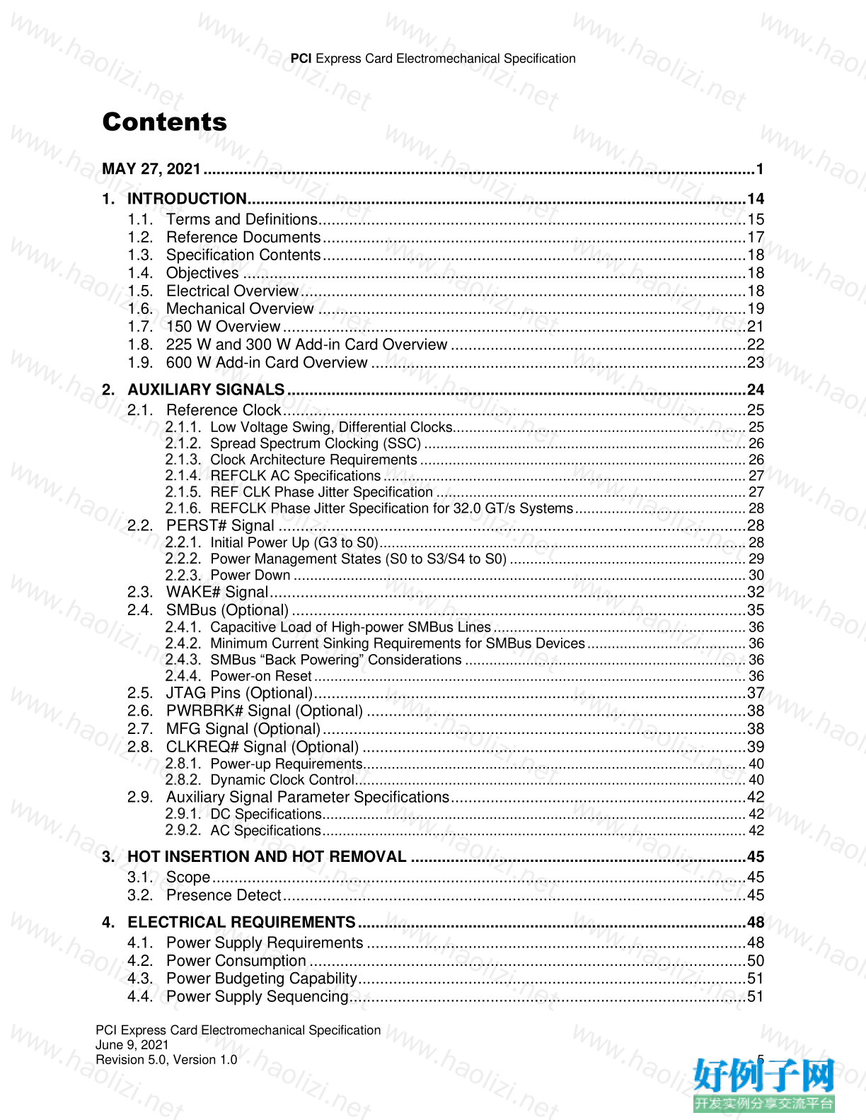
Contents
MAY 27, 2021 ............................................................................................................................. 1
1. INTRODUCTION ................................................................................................................. 14
1.1. Terms and Definitions ................................................................................................. 15
1.2. Reference Documents ................................................................................................ 17
1.3. Specification Contents ................................................................................................ 18
1.4. Objectives .................................................................................................................. 18
1.5. Electrical Overview ..................................................................................................... 18
1.6. Mechanical Overview ................................................................................................. 19
1.7. 150 W Overview ......................................................................................................... 21
1.8. 225 W and 300 W Add-in Card Overview ................................................................... 22
1.9. 600 W Add-in Card Overview ..................................................................................... 23
2. AUXILIARY SIGNALS ........................................................................................................ 24
2.1. Reference Clock ......................................................................................................... 25
Low Voltage Swing, Differential Clocks........................................................................ 25
Spread Spectrum Clocking (SSC) ............................................................................... 26
Clock Architecture Requirements ................................................................................ 26
REFCLK AC Specifications ......................................................................................... 27
REF CLK Phase Jitter Specification ............................................................................ 27
REFCLK Phase Jitter Specification for 32.0 GT/s Systems .......................................... 28
2.2. PERST# Signal .......................................................................................................... 28
Initial Power Up (G3 to S0) .......................................................................................... 28
Power Management States (S0 to S3/S4 to S0) .......................................................... 29
Power Down ............................................................................................................... 30
2.3. WAKE# Signal ............................................................................................................ 32
2.4. SMBus (Optional) ....................................................................................................... 35
Capacitive Load of High-power SMBus Lines .............................................................. 36
Minimum Current Sinking Requirements for SMBus Devices ....................................... 36
SMBus “Back Powering” Considerations ..................................................................... 36
Power-on Reset .......................................................................................................... 36
2.5. JTAG Pins (Optional) .................................................................................................. 37
2.6. PWRBRK# Signal (Optional) ...................................................................................... 38
2.7. MFG Signal (Optional) ................................................................................................ 38
2.8. CLKREQ# Signal (Optional) ....................................................................................... 39
Power-up Requirements.............................................................................................. 40
Dynamic Clock Control ................................................................................................ 40
2.9. Auxiliary Signal Parameter Specifications ................................................................... 42
DC Specifications........................................................................................................ 42
AC Specifications ........................................................................................................ 42
3. HOT INSERTION AND HOT REMOVAL ............................................................................ 45
3.1. Scope ......................................................................................................................... 45
3.2. Presence Detect ......................................................................................................... 45
4. ELECTRICAL REQUIREMENTS ........................................................................................ 48
4.1. Power Supply Requirements ...................................................................................... 48
4.2. Power Consumption ................................................................................................... 50
4.3. Power Budgeting Capability ........................................................................................ 51
4.4. Power Supply Sequencing.......................................................................................... 51
PCI Express Card Electromechanical Specification
PCI Express Card Electromechanical Specification
June 9, 2021
Revision 5.0, Version 1.0 6
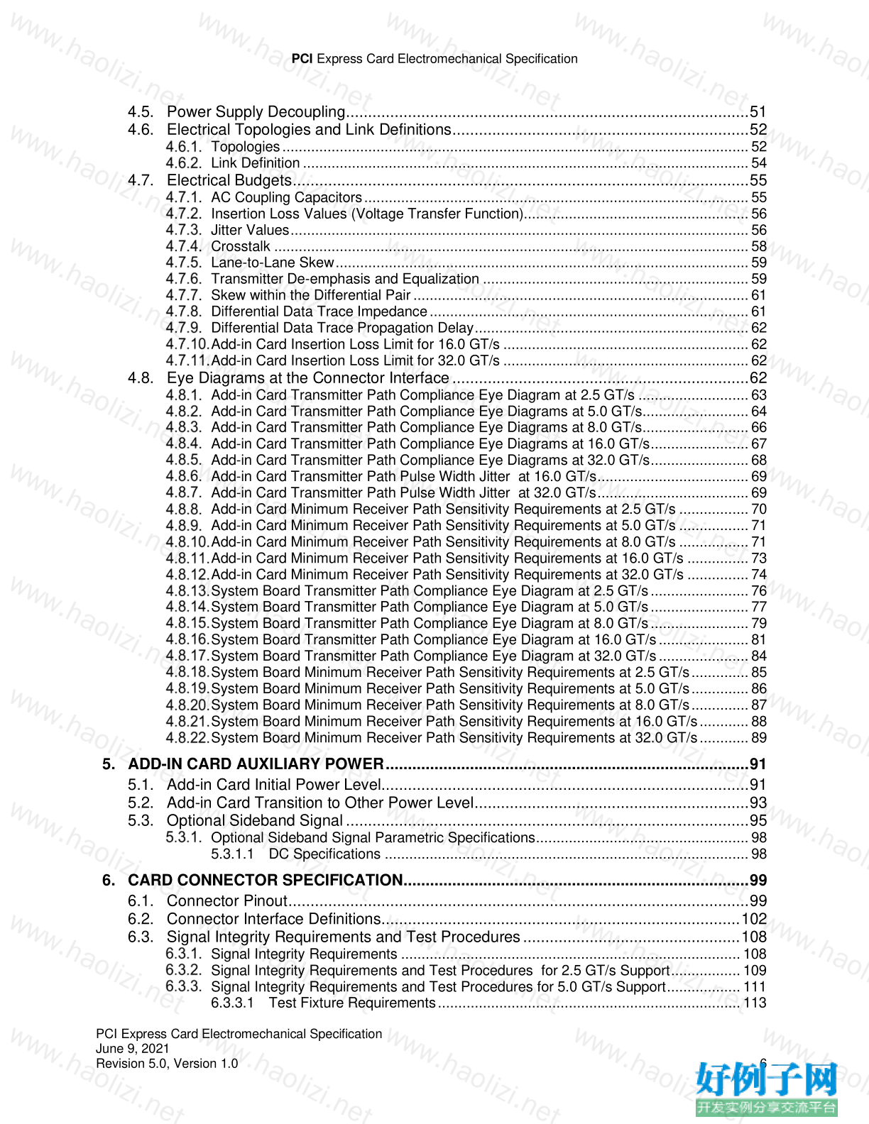
4.5. Power Supply Decoupling........................................................................................... 51
4.6. Electrical Topologies and Link Definitions ................................................................... 52
Topologies .................................................................................................................. 52
Link Definition ............................................................................................................. 54
4.7. Electrical Budgets ....................................................................................................... 55
AC Coupling Capacitors .............................................................................................. 55
Insertion Loss Values (Voltage Transfer Function)....................................................... 56
Jitter Values ................................................................................................................ 56
Crosstalk .................................................................................................................... 58
Lane-to-Lane Skew ..................................................................................................... 59
Transmitter De-emphasis and Equalization ................................................................. 59
Skew within the Differential Pair .................................................................................. 61
Differential Data Trace Impedance .............................................................................. 61
Differential Data Trace Propagation Delay ................................................................... 62
Add-in Card Insertion Loss Limit for 16.0 GT/s ............................................................ 62
Add-in Card Insertion Loss Limit for 32.0 GT/s ............................................................ 62
4.8. Eye Diagrams at the Connector Interface ................................................................... 62
Add-in Card Transmitter Path Compliance Eye Diagram at 2.5 GT/s ........................... 63
Add-in Card Transmitter Path Compliance Eye Diagrams at 5.0 GT/s .......................... 64
Add-in Card Transmitter Path Compliance Eye Diagrams at 8.0 GT/s .......................... 66
Add-in Card Transmitter Path Compliance Eye Diagrams at 16.0 GT/s ........................ 67
Add-in Card Transmitter Path Compliance Eye Diagrams at 32.0 GT/s ........................ 68
Add-in Card Transmitter Path Pulse Width Jitter at 16.0 GT/s ..................................... 69
Add-in Card Transmitter Path Pulse Width Jitter at 32.0 GT/s ..................................... 69
Add-in Card Minimum Receiver Path Sensitivity Requirements at 2.5 GT/s ................. 70
Add-in Card Minimum Receiver Path Sensitivity Requirements at 5.0 GT/s ................. 71
Add-in Card Minimum Receiver Path Sensitivity Requirements at 8.0 GT/s ................. 71
Add-in Card Minimum Receiver Path Sensitivity Requirements at 16.0 GT/s ............... 73
Add-in Card Minimum Receiver Path Sensitivity Requirements at 32.0 GT/s ............... 74
System Board Transmitter Path Compliance Eye Diagram at 2.5 GT/s ........................ 76
System Board Transmitter Path Compliance Eye Diagram at 5.0 GT/s ........................ 77
System Board Transmitter Path Compliance Eye Diagram at 8.0 GT/s ........................ 79
System Board Transmitter Path Compliance Eye Diagram at 16.0 GT/s ...................... 81
System Board Transmitter Path Compliance Eye Diagram at 32.0 GT/s ...................... 84
System Board Minimum Receiver Path Sensitivity Requirements at 2.5 GT/s .............. 85
System Board Minimum Receiver Path Sensitivity Requirements at 5.0 GT/s .............. 86
System Board Minimum Receiver Path Sensitivity Requirements at 8.0 GT/s .............. 87
System Board Minimum Receiver Path Sensitivity Requirements at 16.0 GT/s ............ 88
System Board Minimum Receiver Path Sensitivity Requirements at 32.0 GT/s ............ 89
5. ADD-IN CARD AUXILIARY POWER .................................................................................. 91
5.1. Add-in Card Initial Power Level................................................................................... 91
5.2. Add-in Card Transition to Other Power Level.............................................................. 93
5.3. Optional Sideband Signal ........................................................................................... 95
Optional Sideband Signal Parametric Specifications .................................................... 98
5.3.1.1 DC Specifications ......................................................................................... 98
6. CARD CONNECTOR SPECIFICATION .............................................................................. 99
6.1. Connector Pinout ........................................................................................................ 99
6.2. Connector Interface Definitions................................................................................. 102
6.3. Signal Integrity Requirements and Test Procedures ................................................. 108
Signal Integrity Requirements ................................................................................... 108
Signal Integrity Requirements and Test Procedures for 2.5 GT/s Support ................. 109
Signal Integrity Requirements and Test Procedures for 5.0 GT/s Support .................. 111
6.3.3.1 Test Fixture Requirements .......................................................................... 113
PCI Express Card Electromechanical Specification
PCI Express Card Electromechanical Specification
June 9, 2021
Revision 5.0, Version 1.0 7
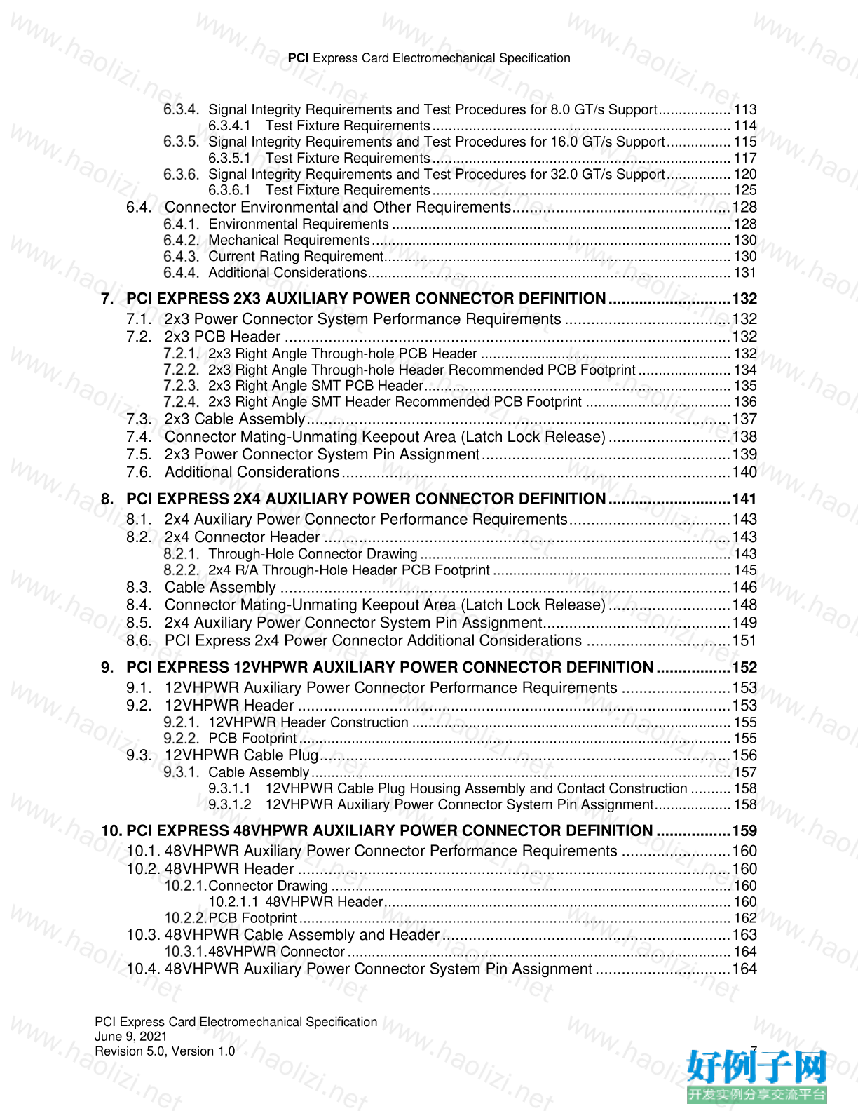
Signal Integrity Requirements and Test Procedures for 8.0 GT/s Support .................. 113
6.3.4.1 Test Fixture Requirements .......................................................................... 114
Signal Integrity Requirements and Test Procedures for 16.0 GT/s Support ................ 115
6.3.5.1 Test Fixture Requirements .......................................................................... 117
Signal Integrity Requirements and Test Procedures for 32.0 GT/s Support ................ 120
6.3.6.1 Test Fixture Requirements .......................................................................... 125
6.4. Connector Environmental and Other Requirements.................................................. 128
Environmental Requirements .................................................................................... 128
Mechanical Requirements ......................................................................................... 130
Current Rating Requirement...................................................................................... 130
Additional Considerations .......................................................................................... 131
7. PCI EXPRESS 2X3 AUXILIARY POWER CONNECTOR DEFINITION ............................ 132
7.1. 2x3 Power Connector System Performance Requirements ...................................... 132
7.2. 2x3 PCB Header ...................................................................................................... 132
2x3 Right Angle Through-hole PCB Header .............................................................. 132
2x3 Right Angle Through-hole Header Recommended PCB Footprint ....................... 134
2x3 Right Angle SMT PCB Header ............................................................................ 135
2x3 Right Angle SMT Header Recommended PCB Footprint .................................... 136
7.3. 2x3 Cable Assembly ................................................................................................. 137
7.4. Connector Mating-Unmating Keepout Area (Latch Lock Release) ............................ 138
7.5. 2x3 Power Connector System Pin Assignment ......................................................... 139
7.6. Additional Considerations ......................................................................................... 140
8. PCI EXPRESS 2X4 AUXILIARY POWER CONNECTOR DEFINITION ............................ 141
8.1. 2x4 Auxiliary Power Connector Performance Requirements ..................................... 143
8.2. 2x4 Connector Header ............................................................................................. 143
Through-Hole Connector Drawing ............................................................................. 143
2x4 R/A Through-Hole Header PCB Footprint ........................................................... 145
8.3. Cable Assembly ....................................................................................................... 146
8.4. Connector Mating-Unmating Keepout Area (Latch Lock Release) ............................ 148
8.5. 2x4 Auxiliary Power Connector System Pin Assignment........................................... 149
8.6. PCI Express 2x4 Power Connector Additional Considerations ................................. 151
9. PCI EXPRESS 12VHPWR AUXILIARY POWER CONNECTOR DEFINITION ................. 152
9.1. 12VHPWR Auxiliary Power Connector Performance Requirements ......................... 153
9.2. 12VHPWR Header ................................................................................................... 153
12VHPWR Header Construction ............................................................................... 155
PCB Footprint ........................................................................................................... 155
9.3. 12VHPWR Cable Plug .............................................................................................. 156
Cable Assembly ........................................................................................................ 157
9.3.1.1 12VHPWR Cable Plug Housing Assembly and Contact Construction .......... 158
9.3.1.2 12VHPWR Auxiliary Power Connector System Pin Assignment ................... 158
10. PCI EXPRESS 48VHPWR AUXILIARY POWER CONNECTOR DEFINITION ................. 159
10.1. 48VHPWR Auxiliary Power Connector Performance Requirements ......................... 160
10.2. 48VHPWR Header ................................................................................................... 160
Connector Drawing ................................................................................................... 160
10.2.1.1 48VHPWR Header ...................................................................................... 160
PCB Footprint ........................................................................................................... 162
10.3. 48VHPWR Cable Assembly and Header .................................................................. 163
48VHPWR Connector ............................................................................................... 164
10.4. 48VHPWR Auxiliary Power Connector System Pin Assignment ............................... 164
PCI Express Card Electromechanical Specification
PCI Express Card Electromechanical Specification
June 9, 2021
Revision 5.0, Version 1.0 8
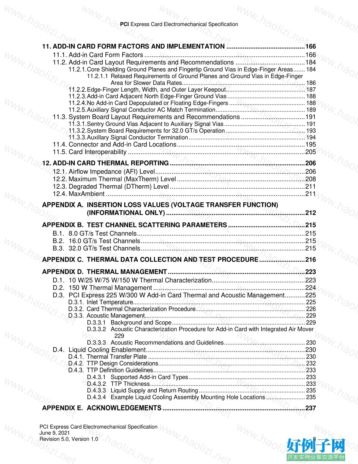
11. ADD-IN CARD FORM FACTORS AND IMPLEMENTATION ........................................... 166
11.1. Add-in Card Form Factors ........................................................................................ 166
11.2. Add-in Card Layout Requirements and Recommendations ...................................... 184
Core Shielding Ground Planes and Fingertip Ground Vias in Edge-Finger Areas ....... 184
11.2.1.1 Relaxed Requirements of Ground Planes and Ground Vias in Edge-Finger
Area for Slower Data Rates ......................................................................... 186
Edge-Finger Length, Width, and Outer Layer Keepout............................................... 187
Add-in Card Adjacent North Edge-Finger Ground Vias .............................................. 188
No Add-in Card Depopulated or Floating Edge-Fingers ............................................. 188
Auxiliary Signal Conductor AC Match Termination ..................................................... 189
11.3. System Board Layout Requirements and Recommendations ................................... 191
Sentry Ground Vias Adjacent to Auxiliary Signal Vias ................................................ 191
System Board Requirements for 32.0 GT/s Operation ............................................... 193
Auxillary Signal Conductor Termination ..................................................................... 194
11.4. Connector and Add-in Card Locations ...................................................................... 195
11.5. Card Interoperability ................................................................................................. 205
12. ADD-IN CARD THERMAL REPORTING .......................................................................... 206
12.1. Airflow Impedance (AFI) Level .................................................................................. 206
12.2. Maximum Thermal (MaxTherm) Level ...................................................................... 208
12.3. Degraded Thermal (DTherm) Level .......................................................................... 211
12.4. MaxAmbient ............................................................................................................. 211
INSERTION LOSS VALUES (VOLTAGE TRANSFER FUNCTION)
(INFORMATIONAL ONLY) ............................................................................ 212
TEST CHANNEL SCATTERING PARAMETERS .......................................... 215
B.1. 8.0 GT/s Test Channels ............................................................................................ 215
B.2. 16.0 GT/s Test Channels .......................................................................................... 215
B.3. 32.0 GT/s Test Channels .......................................................................................... 215
DATA COLLECTION AND TEST PROCEDURE ......................... 216
MANAGEMENT ........................................................................... 223
D.1. 10 W/25 W/75 W/150 W Thermal Characterization................................................... 223
D.2. 150 W Thermal Management ................................................................................... 224
D.3. PCI Express 225 W/300 W Add-in Card Thermal and Acoustic Management ........... 225
D.3.3.1 Background and Scope ............................................................................... 229
D.3.3.2 Acoustic Characterization Procedure for Add-in Card with Integrated Air Mover
229
D.3.3.3 Acoustic Recommendations and Guidelines ................................................ 230
D.4. Liquid Cooling Enablement ....................................................................................... 230
D.4.3.1 Supported Add-in Card Types ..................................................................... 233
D.4.3.2 TTP Thickness ............................................................................................ 233
D.4.3.3 Liquid Supply and Return Routing ............................................................... 235
D.4.3.4 Example Liquid Cooling Assembly Mounting Hole Locations ....................... 235
.............................................................................. 237
PCI Express Card Electromechanical Specification
PCI Express Card Electromechanical Specification
June 9, 2021
Revision 5.0, Version 1.0 9
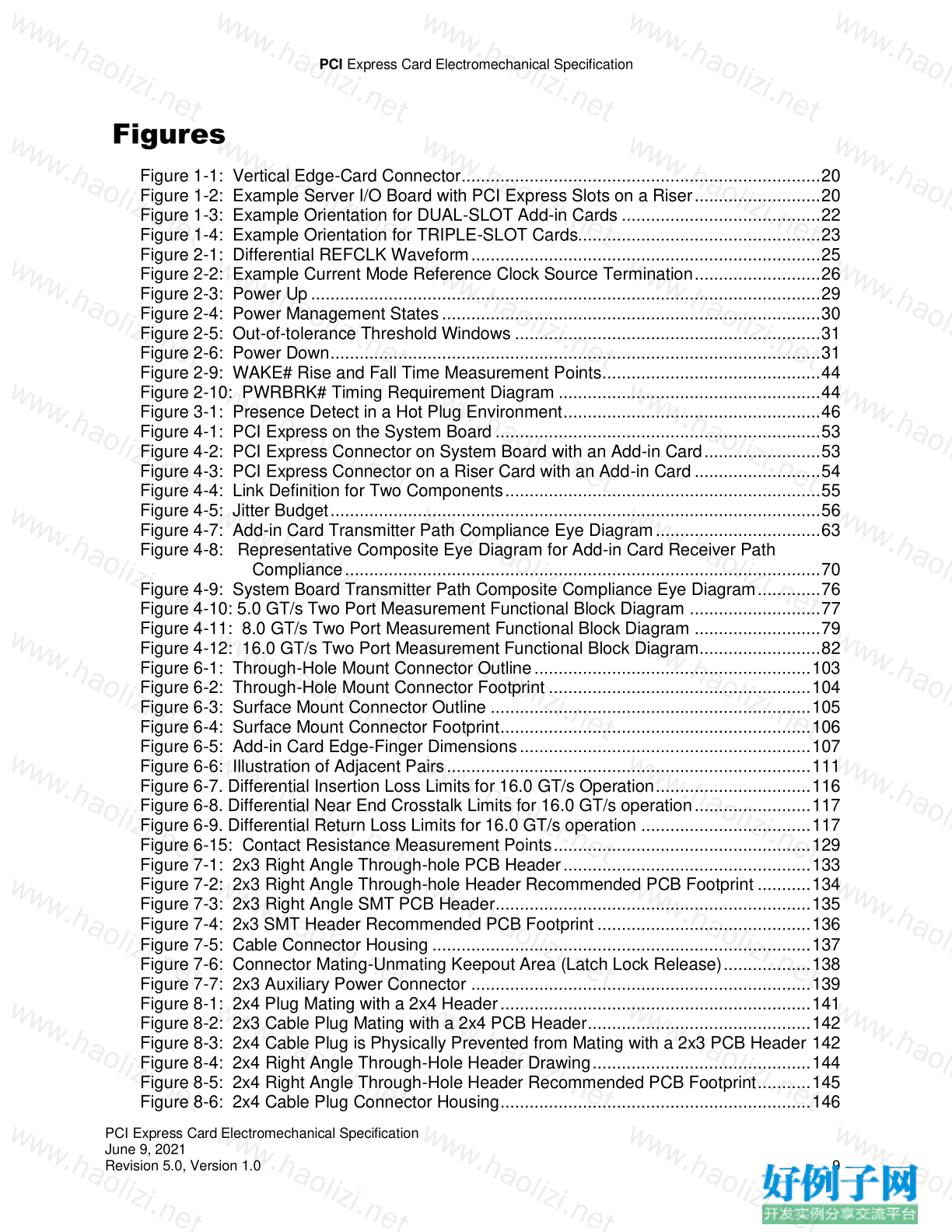
Figures
Figure 1-1: Vertical Edge-Card Connector .......................................................................... 20
Figure 1-2: Example Server I/O Board with PCI Express Slots on a Riser .......................... 20
Figure 1-3: Example Orientation for DUAL-SLOT Add-in Cards ......................................... 22
Figure 1-4: Example Orientation for TRIPLE-SLOT Cards.................................................. 23
Figure 2-1: Differential REFCLK Waveform ........................................................................ 25
Figure 2-2: Example Current Mode Reference Clock Source Termination .......................... 26
Figure 2-3: Power Up ......................................................................................................... 29
Figure 2-4: Power Management States .............................................................................. 30
Figure 2-5: Out-of-tolerance Threshold Windows ............................................................... 31
Figure 2-6: Power Down ..................................................................................................... 31
Figure 2-9: WAKE# Rise and Fall Time Measurement Points ............................................. 44
Figure 2-10: PWRBRK# Timing Requirement Diagram ...................................................... 44
Figure 3-1: Presence Detect in a Hot Plug Environment ..................................................... 46
Figure 4-1: PCI Express on the System Board ................................................................... 53
Figure 4-2: PCI Express Connector on System Board with an Add-in Card ........................ 53
Figure 4-3: PCI Express Connector on a Riser Card with an Add-in Card .......................... 54
Figure 4-4: Link Definition for Two Components ................................................................. 55
Figure 4-5: Jitter Budget ..................................................................................................... 56
Figure 4-7: Add-in Card Transmitter Path Compliance Eye Diagram .................................. 63
Figure 4-8: Representative Composite Eye Diagram for Add-in Card Receiver Path
Compliance .................................................................................................. 70
Figure 4-9: System Board Transmitter Path Composite Compliance Eye Diagram ............. 76
Figure 4-10: 5.0 GT/s Two Port Measurement Functional Block Diagram ........................... 77
Figure 4-11: 8.0 GT/s Two Port Measurement Functional Block Diagram .......................... 79
Figure 4-12: 16.0 GT/s Two Port Measurement Functional Block Diagram......................... 82
Figure 6-1: Through-Hole Mount Connector Outline ......................................................... 103
Figure 6-2: Through-Hole Mount Connector Footprint ...................................................... 104
Figure 6-3: Surface Mount Connector Outline .................................................................. 105
Figure 6-4: Surface Mount Connector Footprint ................................................................ 106
Figure 6-5: Add-in Card Edge-Finger Dimensions ............................................................ 107
Figure 6-6: Illustration of Adjacent Pairs ........................................................................... 111
Figure 6-7. Differential Insertion Loss Limits for 16.0 GT/s Operation ................................ 116
Figure 6-8. Differential Near End Crosstalk Limits for 16.0 GT/s operation ........................ 117
Figure 6-9. Differential Return Loss Limits for 16.0 GT/s operation ................................... 117
Figure 6-15: Contact Resistance Measurement Points ..................................................... 129
Figure 7-1: 2x3 Right Angle Through-hole PCB Header ................................................... 133
Figure 7-2: 2x3 Right Angle Through-hole Header Recommended PCB Footprint ........... 134
Figure 7-3: 2x3 Right Angle SMT PCB Header ................................................................. 135
Figure 7-4: 2x3 SMT Header Recommended PCB Footprint ............................................ 136
Figure 7-5: Cable Connector Housing .............................................................................. 137
Figure 7-6: Connector Mating-Unmating Keepout Area (Latch Lock Release) .................. 138
Figure 7-7: 2x3 Auxiliary Power Connector ...................................................................... 139
Figure 8-1: 2x4 Plug Mating with a 2x4 Header ................................................................ 141
Figure 8-2: 2x3 Cable Plug Mating with a 2x4 PCB Header.............................................. 142
Figure 8-3: 2x4 Cable Plug is Physically Prevented from Mating with a 2x3 PCB Header 142
Figure 8-4: 2x4 Right Angle Through-Hole Header Drawing ............................................. 144
Figure 8-5: 2x4 Right Angle Through-Hole Header Recommended PCB Footprint ........... 145
Figure 8-6: 2x4 Cable Plug Connector Housing ................................................................ 146
PCI Express Card Electromechanical Specification
PCI Express Card Electromechanical Specification
June 9, 2021
Revision 5.0, Version 1.0 10
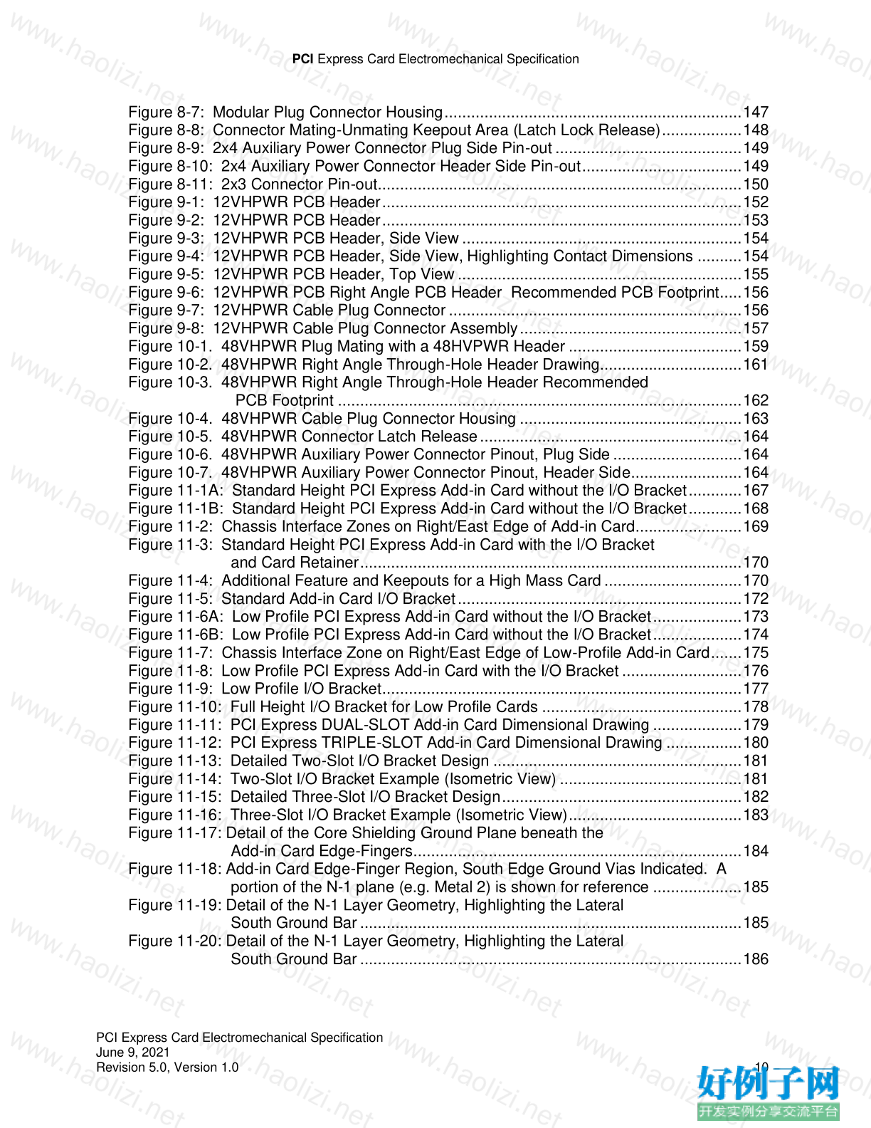
Figure 8-7: Modular Plug Connector Housing ................................................................... 147
Figure 8-8: Connector Mating-Unmating Keepout Area (Latch Lock Release) .................. 148
Figure 8-9: 2x4 Auxiliary Power Connector Plug Side Pin-out .......................................... 149
Figure 8-10: 2x4 Auxiliary Power Connector Header Side Pin-out .................................... 149
Figure 8-11: 2x3 Connector Pin-out .................................................................................. 150
Figure 9-1: 12VHPWR PCB Header ................................................................................. 152
Figure 9-2: 12VHPWR PCB Header ................................................................................. 153
Figure 9-3: 12VHPWR PCB Header, Side View ............................................................... 154
Figure 9-4: 12VHPWR PCB Header, Side View, Highlighting Contact Dimensions .......... 154
Figure 9-5: 12VHPWR PCB Header, Top View ................................................................ 155
Figure 9-6: 12VHPWR PCB Right Angle PCB Header Recommended PCB Footprint..... 156
Figure 9-7: 12VHPWR Cable Plug Connector .................................................................. 156
Figure 9-8: 12VHPWR Cable Plug Connector Assembly .................................................. 157
Figure 10-1. 48VHPWR Plug Mating with a 48HVPWR Header ....................................... 159
Figure 10-2. 48VHPWR Right Angle Through-Hole Header Drawing................................ 161
Figure 10-3. 48VHPWR Right Angle Through-Hole Header Recommended
PCB Footprint ........................................................................................... 162
Figure 10-4. 48VHPWR Cable Plug Connector Housing .................................................. 163
Figure 10-5. 48VHPWR Connector Latch Release ........................................................... 164
Figure 10-6. 48VHPWR Auxiliary Power Connector Pinout, Plug Side ............................. 164
Figure 10-7. 48VHPWR Auxiliary Power Connector Pinout, Header Side ......................... 164
Figure 11-1A: Standard Height PCI Express Add-in Card without the I/O Bracket ............ 167
Figure 11-1B: Standard Height PCI Express Add-in Card without the I/O Bracket ............ 168
Figure 11-2: Chassis Interface Zones on Right/East Edge of Add-in Card ........................ 169
Figure 11-3: Standard Height PCI Express Add-in Card with the I/O Bracket
and Card Retainer ...................................................................................... 170
Figure 11-4: Additional Feature and Keepouts for a High Mass Card ............................... 170
Figure 11-5: Standard Add-in Card I/O Bracket ................................................................ 172
Figure 11-6A: Low Profile PCI Express Add-in Card without the I/O Bracket .................... 173
Figure 11-6B: Low Profile PCI Express Add-in Card without the I/O Bracket .................... 174
Figure 11-7: Chassis Interface Zone on Right/East Edge of Low-Profile Add-in Card ....... 175
Figure 11-8: Low Profile PCI Express Add-in Card with the I/O Bracket ........................... 176
Figure 11-9: Low Profile I/O Bracket ................................................................................. 177
Figure 11-10: Full Height I/O Bracket for Low Profile Cards ............................................. 178
Figure 11-11: PCI Express DUAL-SLOT Add-in Card Dimensional Drawing .................... 179
Figure 11-12: PCI Express TRIPLE-SLOT Add-in Card Dimensional Drawing ................. 180
Figure 11-13: Detailed Two-Slot I/O Bracket Design ........................................................ 181
Figure 11-14: Two-Slot I/O Bracket Example (Isometric View) ......................................... 181
Figure 11-15: Detailed Three-Slot I/O Bracket Design ...................................................... 182
Figure 11-16: Three-Slot I/O Bracket Example (Isometric View) ....................................... 183
Figure 11-17: Detail of the Core Shielding Ground Plane beneath the
Add-in Card Edge-Fingers .......................................................................... 184
Figure 11-18: Add-in Card Edge-Finger Region, South Edge Ground Vias Indicated. A
portion of the N-1 plane (e.g. Metal 2) is shown for reference .................... 185
Figure 11-19: Detail of the N-1 Layer Geometry, Highlighting the Lateral
South Ground Bar ...................................................................................... 185
Figure 11-20: Detail of the N-1 Layer Geometry, Highlighting the Lateral
South Ground Bar ...................................................................................... 186
PCI Express Card Electromechanical Specification
PCI Express Card Electromechanical Specification
June 9, 2021
Revision 5.0, Version 1.0 11
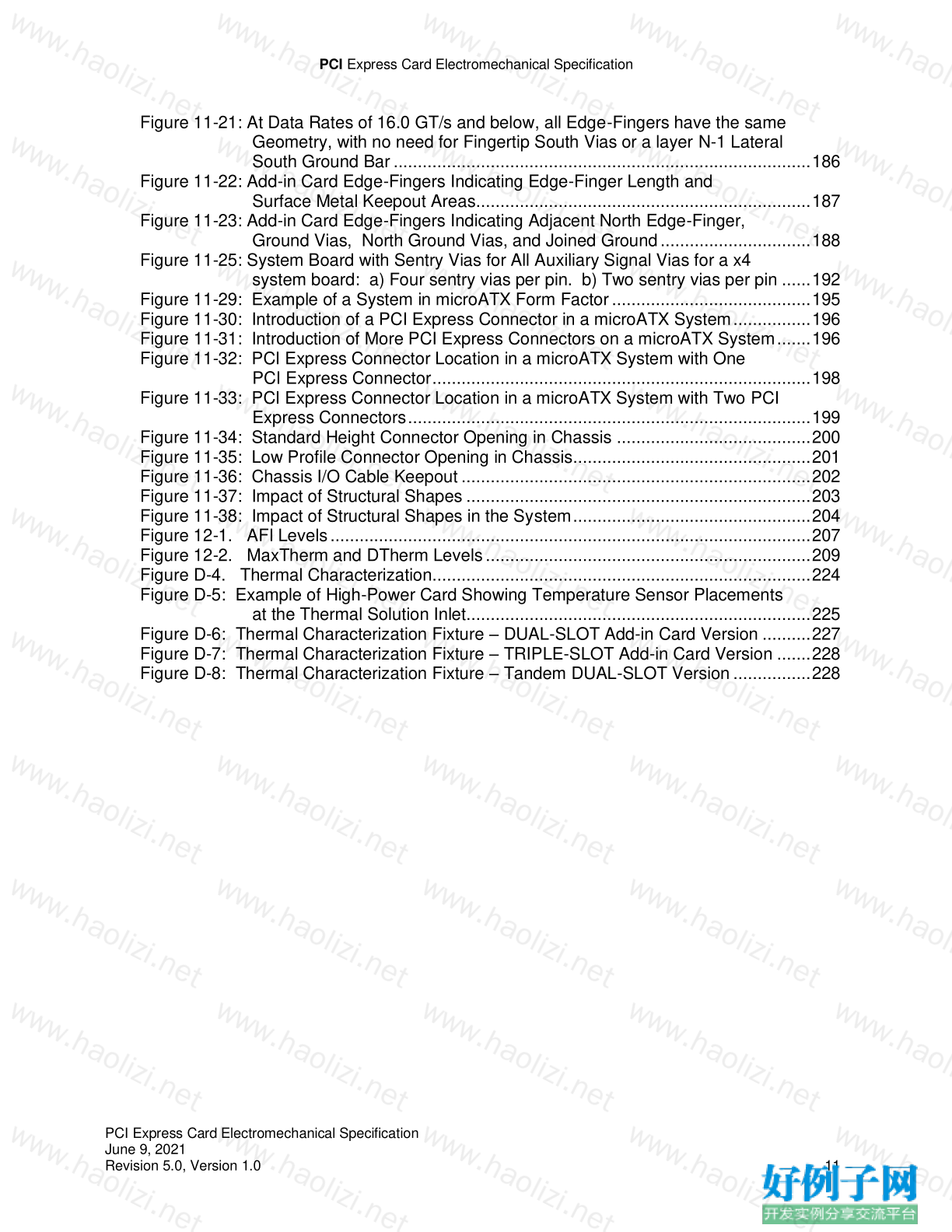
Figure 11-21: At Data Rates of 16.0 GT/s and below, all Edge-Fingers have the same
Geometry, with no need for Fingertip South Vias or a layer N-1 Lateral
South Ground Bar ...................................................................................... 186
Figure 11-22: Add-in Card Edge-Fingers Indicating Edge-Finger Length and
Surface Metal Keepout Areas..................................................................... 187
Figure 11-23: Add-in Card Edge-Fingers Indicating Adjacent North Edge-Finger,
Ground Vias, North Ground Vias, and Joined Ground ............................... 188
Figure 11-25: System Board with Sentry Vias for All Auxiliary Signal Vias for a x4
system board: a) Four sentry vias per pin. b) Two sentry vias per pin ...... 192
Figure 11-29: Example of a System in microATX Form Factor ......................................... 195
Figure 11-30: Introduction of a PCI Express Connector in a microATX System ................ 196
Figure 11-31: Introduction of More PCI Express Connectors on a microATX System ....... 196
Figure 11-32: PCI Express Connector Location in a microATX System with One
PCI Express Connector .............................................................................. 198
Figure 11-33: PCI Express Connector Location in a microATX System with Two PCI
Express Connectors ................................................................................... 199
Figure 11-34: Standard Height Connector Opening in Chassis ........................................ 200
Figure 11-35: Low Profile Connector Opening in Chassis................................................. 201
Figure 11-36: Chassis I/O Cable Keepout ........................................................................ 202
Figure 11-37: Impact of Structural Shapes ....................................................................... 203
Figure 11-38: Impact of Structural Shapes in the System ................................................. 204
Figure 12-1. AFI Levels ................................................................................................... 207
Figure 12-2. MaxTherm and DTherm Levels ................................................................... 209
Figure D-4. Thermal Characterization.............................................................................. 224
Figure D-5: Example of High-Power Card Showing Temperature Sensor Placements
at the Thermal Solution Inlet....................................................................... 225
Figure D-6: Thermal Characterization Fixture – DUAL-SLOT Add-in Card Version .......... 227
Figure D-7: Thermal Characterization Fixture – TRIPLE-SLOT Add-in Card Version ....... 228
Figure D-8: Thermal Characterization Fixture – Tandem DUAL-SLOT Version ................ 228
PCI Express Card Electromechanical Specification
PCI Express Card Electromechanical Specification
June 9, 2021
Revision 5.0, Version 1.0 12
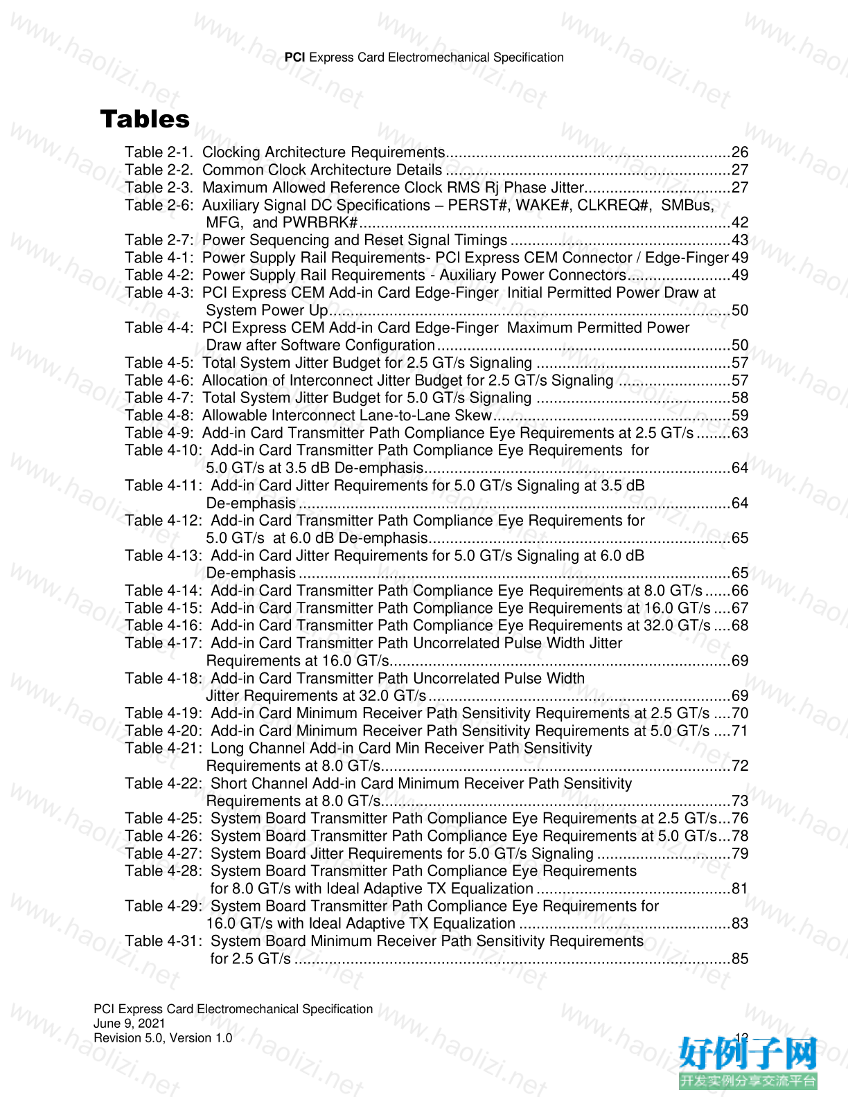
Tables
Table 2-1. Clocking Architecture Requirements .................................................................. 26
Table 2-2. Common Clock Architecture Details .................................................................. 27
Table 2-3. Maximum Allowed Reference Clock RMS Rj Phase Jitter.................................. 27
Table 2-6: Auxiliary Signal DC Specifications – PERST#, WAKE#, CLKREQ#, SMBus,
MFG, and PWRBRK# ...................................................................................... 42
Table 2-7: Power Sequencing and Reset Signal Timings ................................................... 43
Table 4-1: Power Supply Rail Requirements- PCI Express CEM Connector / Edge-Finger 49
Table 4-2: Power Supply Rail Requirements - Auxiliary Power Connectors ........................ 49
Table 4-3: PCI Express CEM Add-in Card Edge-Finger Initial Permitted Power Draw at
System Power Up ............................................................................................. 50
Table 4-4: PCI Express CEM Add-in Card Edge-Finger Maximum Permitted Power
Draw after Software Configuration .................................................................... 50
Table 4-5: Total System Jitter Budget for 2.5 GT/s Signaling ............................................. 57
Table 4-6: Allocation of Interconnect Jitter Budget for 2.5 GT/s Signaling .......................... 57
Table 4-7: Total System Jitter Budget for 5.0 GT/s Signaling ............................................. 58
Table 4-8: Allowable Interconnect Lane-to-Lane Skew ....................................................... 59
Table 4-9: Add-in Card Transmitter Path Compliance Eye Requirements at 2.5 GT/s ........ 63
Table 4-10: Add-in Card Transmitter Path Compliance Eye Requirements for
5.0 GT/s at 3.5 dB De-emphasis....................................................................... 64
Table 4-11: Add-in Card Jitter Requirements for 5.0 GT/s Signaling at 3.5 dB
De-emphasis .................................................................................................... 64
Table 4-12: Add-in Card Transmitter Path Compliance Eye Requirements for
5.0 GT/s at 6.0 dB De-emphasis ...................................................................... 65
Table 4-13: Add-in Card Jitter Requirements for 5.0 GT/s Signaling at 6.0 dB
De-emphasis .................................................................................................... 65
Table 4-14: Add-in Card Transmitter Path Compliance Eye Requirements at 8.0 GT/s ...... 66
Table 4-15: Add-in Card Transmitter Path Compliance Eye Requirements at 16.0 GT/s .... 67
Table 4-16: Add-in Card Transmitter Path Compliance Eye Requirements at 32.0 GT/s .... 68
Table 4-17: Add-in Card Transmitter Path Uncorrelated Pulse Width Jitter
Requirements at 16.0 GT/s ............................................................................... 69
Table 4-18: Add-in Card Transmitter Path Uncorrelated Pulse Width
Jitter Requirements at 32.0 GT/s ...................................................................... 69
Table 4-19: Add-in Card Minimum Receiver Path Sensitivity Requirements at 2.5 GT/s .... 70
Table 4-20: Add-in Card Minimum Receiver Path Sensitivity Requirements at 5.0 GT/s .... 71
Table 4-21: Long Channel Add-in Card Min Receiver Path Sensitivity
Requirements at 8.0 GT/s................................................................................. 72
Table 4-22: Short Channel Add-in Card Minimum Receiver Path Sensitivity
Requirements at 8.0 GT/s................................................................................. 73
Table 4-25: System Board Transmitter Path Compliance Eye Requirements at 2.5 GT/s ... 76
Table 4-26: System Board Transmitter Path Compliance Eye Requirements at 5.0 GT/s ... 78
Table 4-27: System Board Jitter Requirements for 5.0 GT/s Signaling ............................... 79
Table 4-28: System Board Transmitter Path Compliance Eye Requirements
for 8.0 GT/s with Ideal Adaptive TX Equalization ............................................. 81
Table 4-29: System Board Transmitter Path Compliance Eye Requirements for
16.0 GT/s with Ideal Adaptive TX Equalization ................................................. 83
Table 4-31: System Board Minimum Receiver Path Sensitivity Requirements
for 2.5 GT/s ..................................................................................................... 85
PCI Express Card Electromechanical Specification
PCI Express Card Electromechanical Specification
June 9, 2021
Revision 5.0, Version 1.0 13
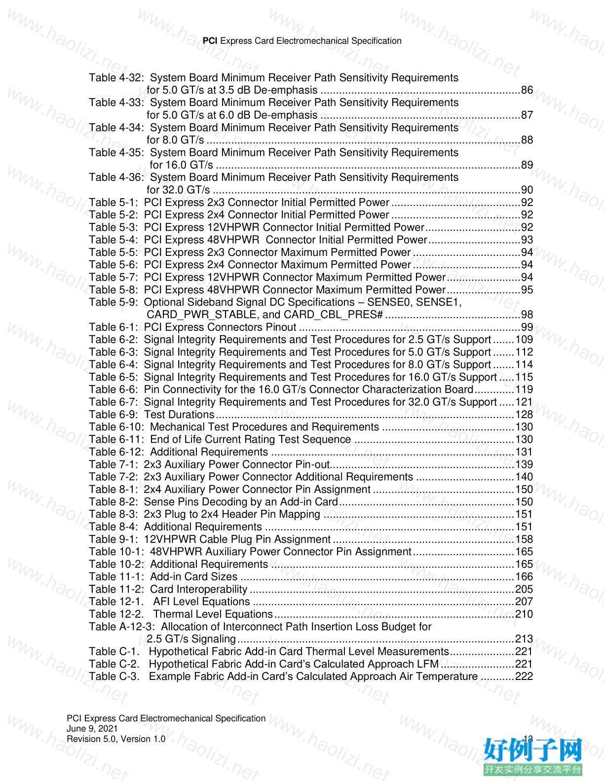
Table 4-32: System Board Minimum Receiver Path Sensitivity Requirements
for 5.0 GT/s at 3.5 dB De-emphasis ................................................................. 86
Table 4-33: System Board Minimum Receiver Path Sensitivity Requirements
for 5.0 GT/s at 6.0 dB De-emphasis ................................................................. 87
Table 4-34: System Board Minimum Receiver Path Sensitivity Requirements
for 8.0 GT/s ...................................................................................................... 88
Table 4-35: System Board Minimum Receiver Path Sensitivity Requirements
for 16.0 GT/s ................................................................................................... 89
Table 4-36: System Board Minimum Receiver Path Sensitivity Requirements
for 32.0 GT/s .................................................................................................... 90
Table 5-1: PCI Express 2x3 Connector Initial Permitted Power .......................................... 92
Table 5-2: PCI Express 2x4 Connector Initial Permitted Power .......................................... 92
Table 5-3: PCI Express 12VHPWR Connector Initial Permitted Power ............................... 92
Table 5-4: PCI Express 48VHPWR Connector Initial Permitted Power .............................. 93
Table 5-5: PCI Express 2x3 Connector Maximum Permitted Power ................................... 94
Table 5-6: PCI Express 2x4 Connector Maximum Permitted Power ................................... 94
Table 5-7: PCI Express 12VHPWR Connector Maximum Permitted Power ........................ 94
Table 5-8: PCI Express 48VHPWR Connector Maximum Permitted Power ........................ 95
Table 5-9: Optional Sideband Signal DC Specifications – SENSE0, SENSE1,
CARD_PWR_STABLE, and CARD_CBL_PRES# ............................................ 98
Table 6-1: PCI Express Connectors Pinout ........................................................................ 99
Table 6-2: Signal Integrity Requirements and Test Procedures for 2.5 GT/s Support ....... 109
Table 6-3: Signal Integrity Requirements and Test Procedures for 5.0 GT/s Support ....... 112
Table 6-4: Signal Integrity Requirements and Test Procedures for 8.0 GT/s Support ....... 114
Table 6-5: Signal Integrity Requirements and Test Procedures for 16.0 GT/s Support ..... 115
Table 6-6: Pin Connectivity for the 16.0 GT/s Connector Characterization Board ............. 119
Table 6-7: Signal Integrity Requirements and Test Procedures for 32.0 GT/s Support ..... 121
Table 6-9: Test Durations ................................................................................................. 128
Table 6-10: Mechanical Test Procedures and Requirements ........................................... 130
Table 6-11: End of Life Current Rating Test Sequence .................................................... 130
Table 6-12: Additional Requirements ............................................................................... 131
Table 7-1: 2x3 Auxiliary Power Connector Pin-out............................................................ 139
Table 7-2: 2x3 Auxiliary Power Connector Additional Requirements ................................ 140
Table 8-1: 2x4 Auxiliary Power Connector Pin Assignment .............................................. 150
Table 8-2: Sense Pins Decoding by an Add-in Card ......................................................... 150
Table 8-3: 2x3 Plug to 2x4 Header Pin Mapping .............................................................. 151
Table 8-4: Additional Requirements ................................................................................. 151
Table 9-1: 12VHPWR Cable Plug Pin Assignment ........................................................... 158
Table 10-1: 48VHPWR Auxiliary Power Connector Pin Assignment ................................. 165
Table 10-2: Additional Requirements ............................................................................... 165
Table 11-1: Add-in Card Sizes ......................................................................................... 166
Table 11-2: Card Interoperability ...................................................................................... 205
Table 12-1. AFI Level Equations ..................................................................................... 207
Table 12-2. Thermal Level Equations .............................................................................. 210
Table A-12-3: Allocation of Interconnect Path Insertion Loss Budget for
2.5 GT/s Signaling .......................................................................................... 213
Table C-1. Hypothetical Fabric Add-in Card Thermal Level Measurements ..................... 221
Table C-2. Hypothetical Fabric Add-in Card’s Calculated Approach LFM ........................ 221
Table C-3. Example Fabric Add-in Card’s Calculated Approach Air Temperature ........... 222
小贴士
感谢您为本站写下的评论,您的评论对其它用户来说具有重要的参考价值,所以请认真填写。
- 类似“顶”、“沙发”之类没有营养的文字,对勤劳贡献的楼主来说是令人沮丧的反馈信息。
- 相信您也不想看到一排文字/表情墙,所以请不要反馈意义不大的重复字符,也请尽量不要纯表情的回复。
- 提问之前请再仔细看一遍楼主的说明,或许是您遗漏了。
- 请勿到处挖坑绊人、招贴广告。既占空间让人厌烦,又没人会搭理,于人于己都无利。
关于好例子网
本站旨在为广大IT学习爱好者提供一个非营利性互相学习交流分享平台。本站所有资源都可以被免费获取学习研究。本站资源来自网友分享,对搜索内容的合法性不具有预见性、识别性、控制性,仅供学习研究,请务必在下载后24小时内给予删除,不得用于其他任何用途,否则后果自负。基于互联网的特殊性,平台无法对用户传输的作品、信息、内容的权属或合法性、安全性、合规性、真实性、科学性、完整权、有效性等进行实质审查;无论平台是否已进行审查,用户均应自行承担因其传输的作品、信息、内容而可能或已经产生的侵权或权属纠纷等法律责任。本站所有资源不代表本站的观点或立场,基于网友分享,根据中国法律《信息网络传播权保护条例》第二十二与二十三条之规定,若资源存在侵权或相关问题请联系本站客服人员,点此联系我们。关于更多版权及免责申明参见 版权及免责申明


网友评论
我要评论