实例介绍
【实例截图】

【核心代码】
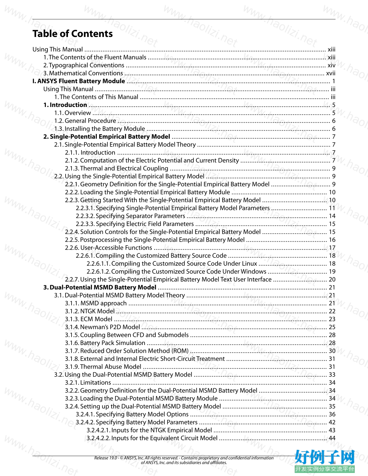
Table of Contents
Using This Manual ...................................................................................................................................... xiii
1.The Contents of the Fluent Manuals ................................................................................................... xiii
2.Typographical Conventions ............................................................................................................... xiv
3. Mathematical Conventions ............................................................................................................... xvii
I. ANSYS Fluent Battery Module ................................................................................................................. 1
Using This Manual .................................................................................................................................. iii
1.The Contents of This Manual ......................................................................................................... iii
1. Introduction ...................................................................................................................................... 5
1.1. Overview .................................................................................................................................... 5
1.2. General Procedure ...................................................................................................................... 6
1.3. Installing the Battery Module ...................................................................................................... 6
2. Single-Potential Empirical Battery Model ........................................................................................ 7
2.1. Single-Potential Empirical Battery Model Theory .......................................................................... 7
2.1.1. Introduction ...................................................................................................................... 7
2.1.2. Computation of the Electric Potential and Current Density .................................................. 7
2.1.3.Thermal and Electrical Coupling ......................................................................................... 9
2.2. Using the Single-Potential Empirical Battery Model ..................................................................... 9
2.2.1. Geometry Definition for the Single-Potential Empirical Battery Model ................................. 9
2.2.2. Loading the Single-Potential Empirical Battery Module ..................................................... 10
2.2.3. Getting Started With the Single-Potential Empirical Battery Model .................................... 10
2.2.3.1. Specifying Single-Potential Empirical Battery Model Parameters ............................... 11
2.2.3.2. Specifying Separator Parameters .............................................................................. 14
2.2.3.3. Specifying Electric Field Parameters ......................................................................... 15
2.2.4. Solution Controls for the Single-Potential Empirical Battery Model .................................... 15
2.2.5. Postprocessing the Single-Potential Empirical Battery Model ............................................. 16
2.2.6. User-Accessible Functions ................................................................................................ 17
2.2.6.1. Compiling the Customized Battery Source Code ....................................................... 18
2.2.6.1.1. Compiling the Customized Source Code Under Linux ...................................... 18
2.2.6.1.2. Compiling the Customized Source Code Under Windows ................................. 19
2.2.7. Using the Single-Potential Empirical Battery Model Text User Interface .............................. 20
3. Dual-Potential MSMD Battery Model .............................................................................................. 21
3.1. Dual-Potential MSMD Battery Model Theory .............................................................................. 21
3.1.1. MSMD approach .............................................................................................................. 21
3.1.2. NTGK Model ..................................................................................................................... 22
3.1.3. ECM Model ...................................................................................................................... 23
3.1.4. Newman’s P2D Model ....................................................................................................... 25
3.1.5. Coupling Between CFD and Submodels ............................................................................ 28
3.1.6. Battery Pack Simulation .................................................................................................... 28
3.1.7. Reduced Order Solution Method (ROM) ............................................................................ 30
3.1.8. External and Internal Electric Short-Circuit Treatment ........................................................ 31
3.1.9.Thermal Abuse Model ...................................................................................................... 31
3.2. Using the Dual-Potential MSMD Battery Model .......................................................................... 33
3.2.1. Limitations ....................................................................................................................... 34
3.2.2. Geometry Definition for the Dual-Potential MSMD Battery Model ...................................... 34
3.2.3. Loading the Dual-Potential MSMD Battery Module ............................................................ 34
3.2.4. Setting up the Dual-Potential MSMD Battery Model .......................................................... 35
3.2.4.1. Specifying Battery Model Options ............................................................................ 36
3.2.4.2. Specifying Battery Model Parameters ....................................................................... 42
3.2.4.2.1. Inputs for the NTGK Empirical Model ............................................................... 43
3.2.4.2.2. Inputs for the Equivalent Circuit Model ............................................................ 44
iii
Release 19.0 - © ANSYS, Inc. All rights reserved. - Contains proprietary and confidential information
of ANSYS, Inc. and its subsidiaries and affiliates.
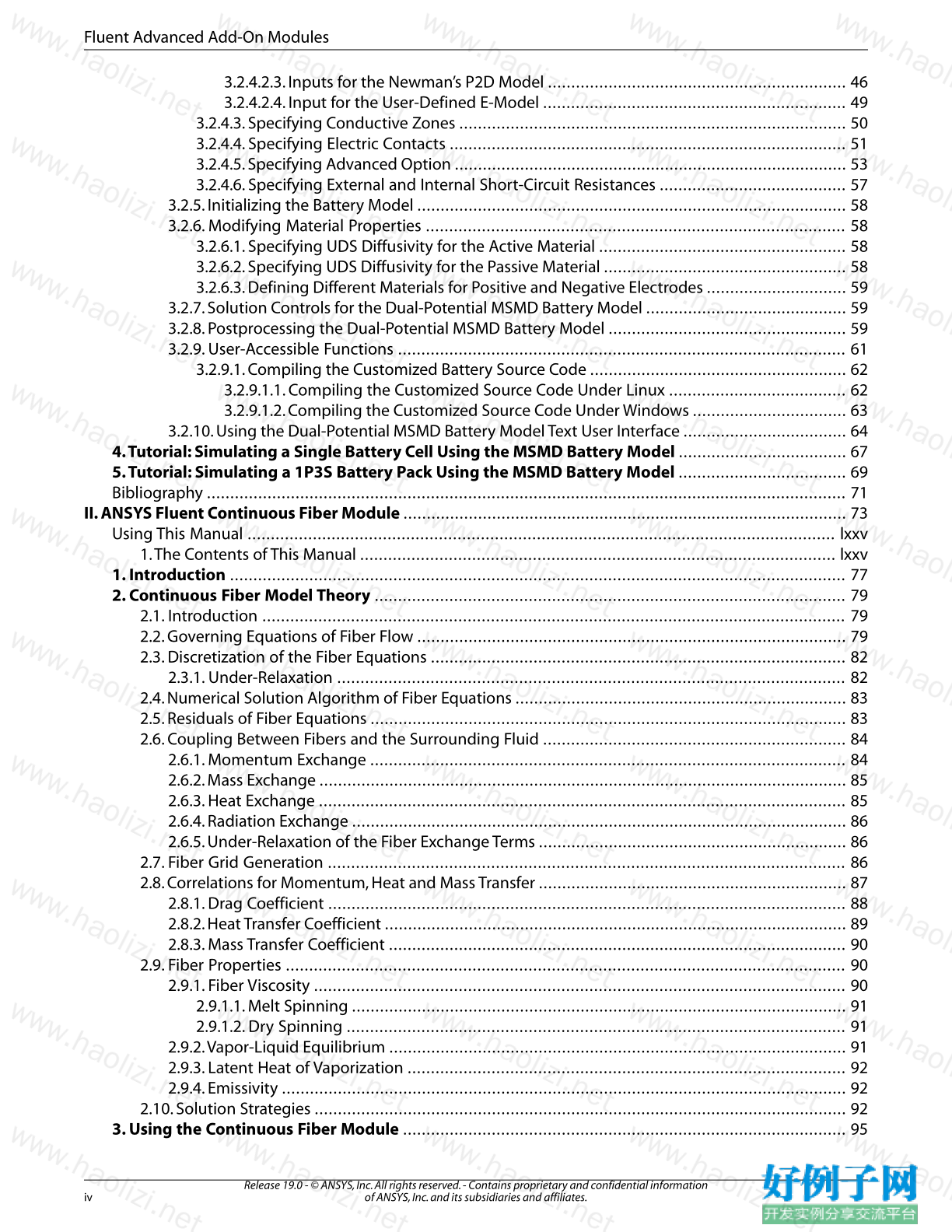
3.2.4.2.3. Inputs for the Newman’s P2D Model ................................................................ 46
3.2.4.2.4. Input for the User-Defined E-Model ................................................................. 49
3.2.4.3. Specifying Conductive Zones ................................................................................... 50
3.2.4.4. Specifying Electric Contacts ..................................................................................... 51
3.2.4.5. Specifying Advanced Option .................................................................................... 53
3.2.4.6. Specifying External and Internal Short-Circuit Resistances ........................................ 57
3.2.5. Initializing the Battery Model ............................................................................................ 58
3.2.6. Modifying Material Properties .......................................................................................... 58
3.2.6.1. Specifying UDS Diffusivity for the Active Material ..................................................... 58
3.2.6.2. Specifying UDS Diffusivity for the Passive Material .................................................... 58
3.2.6.3. Defining Different Materials for Positive and Negative Electrodes .............................. 59
3.2.7. Solution Controls for the Dual-Potential MSMD Battery Model ........................................... 59
3.2.8. Postprocessing the Dual-Potential MSMD Battery Model ................................................... 59
3.2.9. User-Accessible Functions ................................................................................................ 61
3.2.9.1. Compiling the Customized Battery Source Code ....................................................... 62
3.2.9.1.1. Compiling the Customized Source Code Under Linux ...................................... 62
3.2.9.1.2. Compiling the Customized Source Code Under Windows ................................. 63
3.2.10. Using the Dual-Potential MSMD Battery Model Text User Interface ................................... 64
4.Tutorial: Simulating a Single Battery Cell Using the MSMD Battery Model .................................... 67
5.Tutorial: Simulating a 1P3S Battery Pack Using the MSMD Battery Model .................................... 69
Bibliography ......................................................................................................................................... 71
II. ANSYS Fluent Continuous Fiber Module ............................................................................................... 73
Using This Manual .............................................................................................................................. lxxv
1.The Contents of This Manual ...................................................................................................... lxxv
1. Introduction .................................................................................................................................... 77
2. Continuous Fiber Model Theory ..................................................................................................... 79
2.1. Introduction ............................................................................................................................. 79
2.2. Governing Equations of Fiber Flow ............................................................................................ 79
2.3. Discretization of the Fiber Equations ......................................................................................... 82
2.3.1. Under-Relaxation ............................................................................................................. 82
2.4. Numerical Solution Algorithm of Fiber Equations ....................................................................... 83
2.5. Residuals of Fiber Equations ...................................................................................................... 83
2.6. Coupling Between Fibers and the Surrounding Fluid ................................................................. 84
2.6.1. Momentum Exchange ...................................................................................................... 84
2.6.2. Mass Exchange ................................................................................................................. 85
2.6.3. Heat Exchange ................................................................................................................. 85
2.6.4. Radiation Exchange .......................................................................................................... 86
2.6.5. Under-Relaxation of the Fiber Exchange Terms .................................................................. 86
2.7. Fiber Grid Generation ............................................................................................................... 86
2.8. Correlations for Momentum, Heat and Mass Transfer .................................................................. 87
2.8.1. Drag Coefficient ............................................................................................................... 88
2.8.2. Heat Transfer Coefficient ................................................................................................... 89
2.8.3. Mass Transfer Coefficient .................................................................................................. 90
2.9. Fiber Properties ........................................................................................................................ 90
2.9.1. Fiber Viscosity .................................................................................................................. 90
2.9.1.1. Melt Spinning .......................................................................................................... 91
2.9.1.2. Dry Spinning ........................................................................................................... 91
2.9.2.Vapor-Liquid Equilibrium .................................................................................................. 91
2.9.3. Latent Heat of Vaporization .............................................................................................. 92
2.9.4. Emissivity ......................................................................................................................... 92
2.10. Solution Strategies .................................................................................................................. 92
3. Using the Continuous Fiber Module ............................................................................................... 95
Release 19.0 - © ANSYS, Inc. All rights reserved. - Contains proprietary and confidential information
of ANSYS, Inc. and its subsidiaries and affiliates. iv
Fluent Advanced Add-On Modules
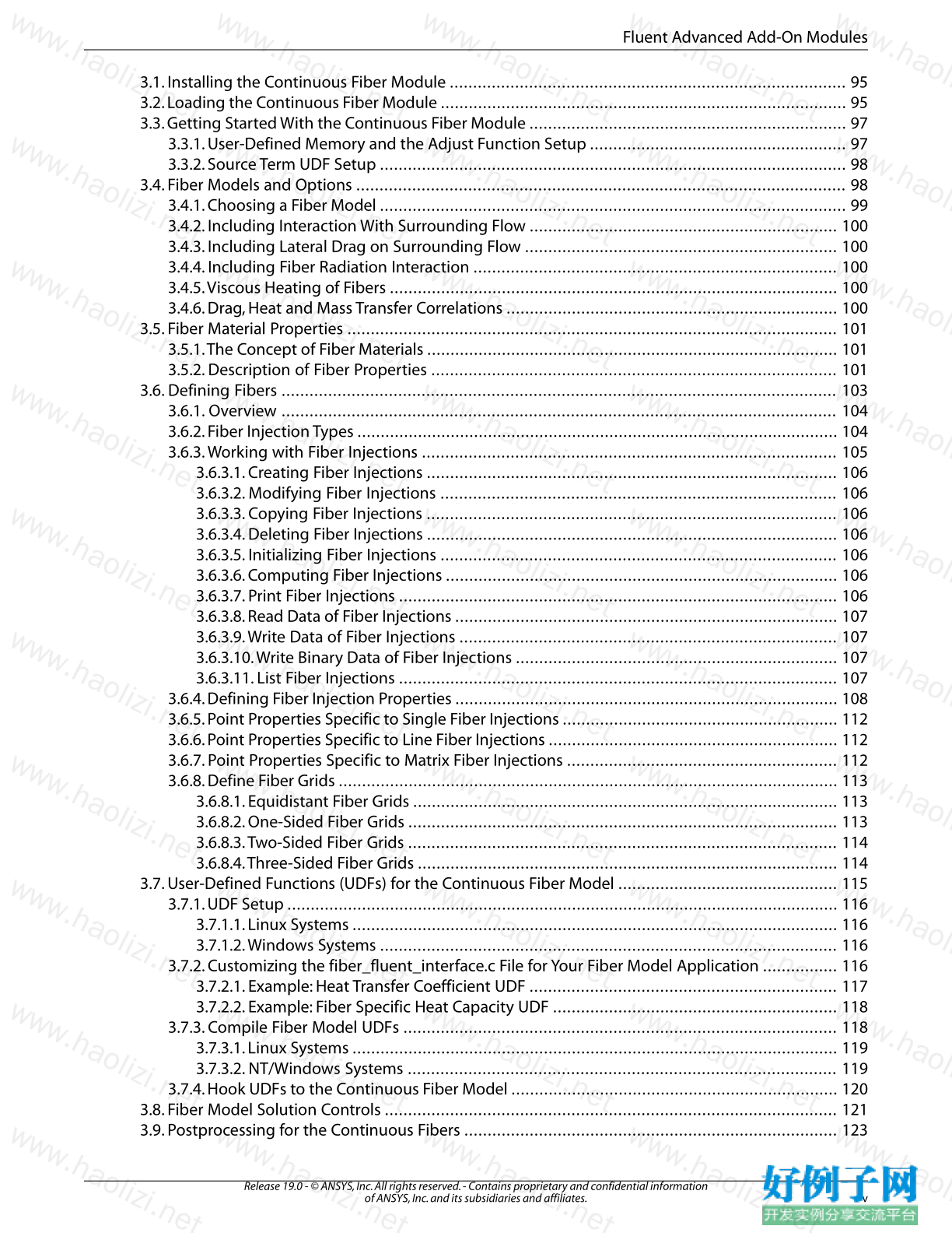
3.1. Installing the Continuous Fiber Module ..................................................................................... 95
3.2. Loading the Continuous Fiber Module ....................................................................................... 95
3.3. Getting Started With the Continuous Fiber Module .................................................................... 97
3.3.1. User-Defined Memory and the Adjust Function Setup ....................................................... 97
3.3.2. Source Term UDF Setup .................................................................................................... 98
3.4. Fiber Models and Options ......................................................................................................... 98
3.4.1. Choosing a Fiber Model .................................................................................................... 99
3.4.2. Including Interaction With Surrounding Flow .................................................................. 100
3.4.3. Including Lateral Drag on Surrounding Flow ................................................................... 100
3.4.4. Including Fiber Radiation Interaction .............................................................................. 100
3.4.5.Viscous Heating of Fibers ................................................................................................ 100
3.4.6. Drag, Heat and Mass Transfer Correlations ....................................................................... 100
3.5. Fiber Material Properties ......................................................................................................... 101
3.5.1.The Concept of Fiber Materials ........................................................................................ 101
3.5.2. Description of Fiber Properties ....................................................................................... 101
3.6. Defining Fibers ....................................................................................................................... 103
3.6.1. Overview ....................................................................................................................... 104
3.6.2. Fiber Injection Types ....................................................................................................... 104
3.6.3.Working with Fiber Injections ......................................................................................... 105
3.6.3.1. Creating Fiber Injections ........................................................................................ 106
3.6.3.2. Modifying Fiber Injections ..................................................................................... 106
3.6.3.3. Copying Fiber Injections ........................................................................................ 106
3.6.3.4. Deleting Fiber Injections ........................................................................................ 106
3.6.3.5. Initializing Fiber Injections ..................................................................................... 106
3.6.3.6. Computing Fiber Injections .................................................................................... 106
3.6.3.7. Print Fiber Injections .............................................................................................. 106
3.6.3.8. Read Data of Fiber Injections .................................................................................. 107
3.6.3.9.Write Data of Fiber Injections ................................................................................. 107
3.6.3.10.Write Binary Data of Fiber Injections ..................................................................... 107
3.6.3.11. List Fiber Injections .............................................................................................. 107
3.6.4. Defining Fiber Injection Properties .................................................................................. 108
3.6.5. Point Properties Specific to Single Fiber Injections ........................................................... 112
3.6.6. Point Properties Specific to Line Fiber Injections .............................................................. 112
3.6.7. Point Properties Specific to Matrix Fiber Injections .......................................................... 112
3.6.8. Define Fiber Grids ........................................................................................................... 113
3.6.8.1. Equidistant Fiber Grids ........................................................................................... 113
3.6.8.2. One-Sided Fiber Grids ............................................................................................ 113
3.6.8.3.Two-Sided Fiber Grids ............................................................................................ 114
3.6.8.4.Three-Sided Fiber Grids .......................................................................................... 114
3.7. User-Defined Functions (UDFs) for the Continuous Fiber Model ............................................... 115
3.7.1. UDF Setup ...................................................................................................................... 116
3.7.1.1. Linux Systems ........................................................................................................ 116
3.7.1.2.Windows Systems .................................................................................................. 116
3.7.2. Customizing the fiber_fluent_interface.c File for Your Fiber Model Application ................ 116
3.7.2.1. Example: Heat Transfer Coefficient UDF .................................................................. 117
3.7.2.2. Example: Fiber Specific Heat Capacity UDF ............................................................. 118
3.7.3. Compile Fiber Model UDFs ............................................................................................. 118
3.7.3.1. Linux Systems ........................................................................................................ 119
3.7.3.2. NT/Windows Systems ............................................................................................ 119
3.7.4. Hook UDFs to the Continuous Fiber Model ...................................................................... 120
3.8. Fiber Model Solution Controls ................................................................................................. 121
3.9. Postprocessing for the Continuous Fibers ................................................................................ 123
v
Release 19.0 - © ANSYS, Inc. All rights reserved. - Contains proprietary and confidential information
of ANSYS, Inc. and its subsidiaries and affiliates.
Fluent Advanced Add-On Modules
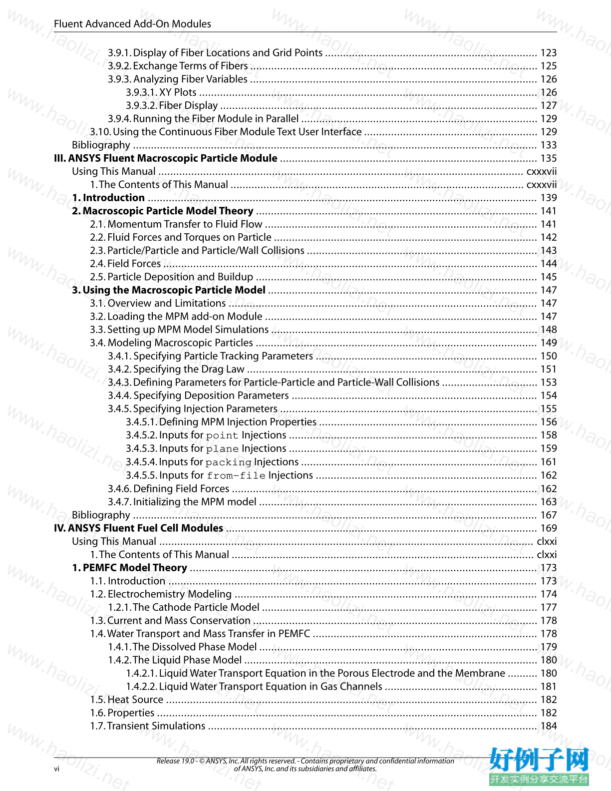
3.9.1. Display of Fiber Locations and Grid Points ....................................................................... 123
3.9.2. Exchange Terms of Fibers ................................................................................................ 125
3.9.3. Analyzing Fiber Variables ................................................................................................ 126
3.9.3.1. XY Plots ................................................................................................................. 126
3.9.3.2. Fiber Display .......................................................................................................... 127
3.9.4. Running the Fiber Module in Parallel ............................................................................... 129
3.10. Using the Continuous Fiber Module Text User Interface .......................................................... 129
Bibliography ....................................................................................................................................... 133
III. ANSYS Fluent Macroscopic Particle Module ...................................................................................... 135
Using This Manual .......................................................................................................................... cxxxvii
1.The Contents of This Manual .................................................................................................. cxxxvii
1. Introduction .................................................................................................................................. 139
2. Macroscopic Particle Model Theory .............................................................................................. 141
2.1. Momentum Transfer to Fluid Flow ........................................................................................... 141
2.2. Fluid Forces and Torques on Particle ........................................................................................ 142
2.3. Particle/Particle and Particle/Wall Collisions ............................................................................. 143
2.4. Field Forces ............................................................................................................................. 144
2.5. Particle Deposition and Buildup .............................................................................................. 145
3. Using the Macroscopic Particle Model .......................................................................................... 147
3.1. Overview and Limitations ....................................................................................................... 147
3.2. Loading the MPM add-on Module ........................................................................................... 147
3.3. Setting up MPM Model Simulations ......................................................................................... 148
3.4. Modeling Macroscopic Particles .............................................................................................. 149
3.4.1. Specifying Particle Tracking Parameters .......................................................................... 150
3.4.2. Specifying the Drag Law ................................................................................................. 151
3.4.3. Defining Parameters for Particle-Particle and Particle-Wall Collisions ................................ 153
3.4.4. Specifying Deposition Parameters .................................................................................. 154
3.4.5. Specifying Injection Parameters ...................................................................................... 155
3.4.5.1. Defining MPM Injection Properties ......................................................................... 156
3.4.5.2. Inputs for point Injections ................................................................................... 158
3.4.5.3. Inputs for plane Injections ................................................................................... 159
3.4.5.4. Inputs for packing Injections ............................................................................... 161
3.4.5.5. Inputs for from-file Injections .......................................................................... 162
3.4.6. Defining Field Forces ...................................................................................................... 162
3.4.7. Initializing the MPM model ............................................................................................. 163
Bibliography ....................................................................................................................................... 167
IV. ANSYS Fluent Fuel Cell Modules ........................................................................................................ 169
Using This Manual ............................................................................................................................. clxxi
1.The Contents of This Manual ..................................................................................................... clxxi
1. PEMFC Model Theory .................................................................................................................... 173
1.1. Introduction ........................................................................................................................... 173
1.2. Electrochemistry Modeling ..................................................................................................... 174
1.2.1.The Cathode Particle Model ............................................................................................ 177
1.3. Current and Mass Conservation ............................................................................................... 178
1.4.Water Transport and Mass Transfer in PEMFC ........................................................................... 178
1.4.1.The Dissolved Phase Model ............................................................................................. 179
1.4.2.The Liquid Phase Model .................................................................................................. 180
1.4.2.1. Liquid Water Transport Equation in the Porous Electrode and the Membrane .......... 180
1.4.2.2. Liquid Water Transport Equation in Gas Channels ................................................... 181
1.5. Heat Source ............................................................................................................................ 182
1.6. Properties ............................................................................................................................... 182
1.7.Transient Simulations .............................................................................................................. 184
Release 19.0 - © ANSYS, Inc. All rights reserved. - Contains proprietary and confidential information
of ANSYS, Inc. and its subsidiaries and affiliates. vi
Fluent Advanced Add-On Modules
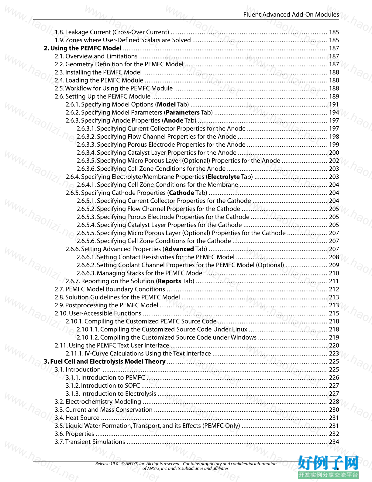
1.8. Leakage Current (Cross-Over Current) ...................................................................................... 185
1.9. Zones where User-Defined Scalars are Solved .......................................................................... 185
2. Using the PEMFC Model ................................................................................................................ 187
2.1. Overview and Limitations ....................................................................................................... 187
2.2. Geometry Definition for the PEMFC Model .............................................................................. 187
2.3. Installing the PEMFC Model ..................................................................................................... 188
2.4. Loading the PEMFC Module .................................................................................................... 188
2.5.Workflow for Using the PEMFC Module .................................................................................... 188
2.6. Setting Up the PEMFC Module ................................................................................................ 189
2.6.1. Specifying Model Options (ModelTab) ........................................................................... 191
2.6.2. Specifying Model Parameters (ParametersTab) .............................................................. 194
2.6.3. Specifying Anode Properties (AnodeTab) ....................................................................... 197
2.6.3.1. Specifying Current Collector Properties for the Anode ............................................ 197
2.6.3.2. Specifying Flow Channel Properties for the Anode ................................................. 198
2.6.3.3. Specifying Porous Electrode Properties for the Anode ............................................ 199
2.6.3.4. Specifying Catalyst Layer Properties for the Anode ................................................. 200
2.6.3.5. Specifying Micro Porous Layer (Optional) Properties for the Anode ......................... 202
2.6.3.6. Specifying Cell Zone Conditions for the Anode ....................................................... 203
2.6.4. Specifying Electrolyte/Membrane Properties (ElectrolyteTab) ........................................ 203
2.6.4.1. Specifying Cell Zone Conditions for the Membrane ................................................ 204
2.6.5. Specifying Cathode Properties (CathodeTab) ................................................................. 204
2.6.5.1. Specifying Current Collector Properties for the Cathode ......................................... 204
2.6.5.2. Specifying Flow Channel Properties for the Cathode ............................................... 205
2.6.5.3. Specifying Porous Electrode Properties for the Cathode .......................................... 205
2.6.5.4. Specifying Catalyst Layer Properties for the Cathode .............................................. 205
2.6.5.5. Specifying Micro Porous Layer (Optional) Properties for the Cathode ...................... 207
2.6.5.6. Specifying Cell Zone Conditions for the Cathode .................................................... 207
2.6.6. Setting Advanced Properties (AdvancedTab) ................................................................. 207
2.6.6.1. Setting Contact Resistivities for the PEMFC Model .................................................. 208
2.6.6.2. Setting Coolant Channel Properties for the PEMFC Model (Optional) ....................... 209
2.6.6.3. Managing Stacks for the PEMFC Model ................................................................... 210
2.6.7. Reporting on the Solution (Reports Tab) ........................................................................ 211
2.7. PEMFC Model Boundary Conditions ........................................................................................ 212
2.8. Solution Guidelines for the PEMFC Model ................................................................................ 213
2.9. Postprocessing the PEMFC Model ............................................................................................ 213
2.10. User-Accessible Functions ..................................................................................................... 215
2.10.1. Compiling the Customized PEMFC Source Code ............................................................ 218
2.10.1.1. Compiling the Customized Source Code Under Linux ........................................... 218
2.10.1.2. Compiling the Customized Source Code under Windows ...................................... 219
2.11. Using the PEMFC Text User Interface ...................................................................................... 220
2.11.1. IV-Curve Calculations Using the Text Interface ............................................................... 223
3. Fuel Cell and Electrolysis Model Theory ........................................................................................ 225
3.1. Introduction ........................................................................................................................... 225
3.1.1. Introduction to PEMFC ................................................................................................... 226
3.1.2. Introduction to SOFC ...................................................................................................... 227
3.1.3. Introduction to Electrolysis ............................................................................................. 227
3.2. Electrochemistry Modeling ..................................................................................................... 228
3.3. Current and Mass Conservation ............................................................................................... 230
3.4. Heat Source ............................................................................................................................ 231
3.5. Liquid Water Formation,Transport, and its Effects (PEMFC Only) ............................................... 231
3.6. Properties ............................................................................................................................... 232
3.7.Transient Simulations .............................................................................................................. 234
vii
Release 19.0 - © ANSYS, Inc. All rights reserved. - Contains proprietary and confidential information
of ANSYS, Inc. and its subsidiaries and affiliates.
Fluent Advanced Add-On Modules
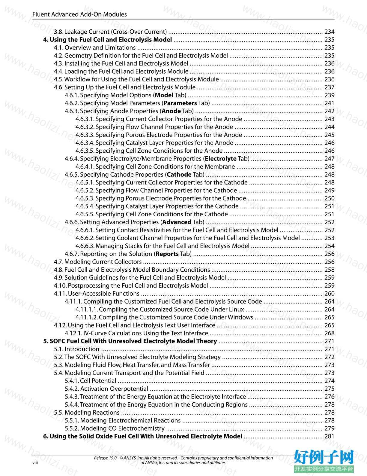
3.8. Leakage Current (Cross-Over Current) ...................................................................................... 234
4. Using the Fuel Cell and Electrolysis Model ................................................................................... 235
4.1. Overview and Limitations ....................................................................................................... 235
4.2. Geometry Definition for the Fuel Cell and Electrolysis Model .................................................... 235
4.3. Installing the Fuel Cell and Electrolysis Model .......................................................................... 236
4.4. Loading the Fuel Cell and Electrolysis Module .......................................................................... 236
4.5.Workflow for Using the Fuel Cell and Electrolysis Module ......................................................... 236
4.6. Setting Up the Fuel Cell and Electrolysis Module ...................................................................... 237
4.6.1. Specifying Model Options (ModelTab) ........................................................................... 239
4.6.2. Specifying Model Parameters (ParametersTab) .............................................................. 241
4.6.3. Specifying Anode Properties (AnodeTab) ....................................................................... 242
4.6.3.1. Specifying Current Collector Properties for the Anode ............................................ 243
4.6.3.2. Specifying Flow Channel Properties for the Anode ................................................. 244
4.6.3.3. Specifying Porous Electrode Properties for the Anode ............................................ 245
4.6.3.4. Specifying Catalyst Layer Properties for the Anode ................................................. 246
4.6.3.5. Specifying Cell Zone Conditions for the Anode ....................................................... 246
4.6.4. Specifying Electrolyte/Membrane Properties (ElectrolyteTab) ........................................ 247
4.6.4.1. Specifying Cell Zone Conditions for the Membrane ................................................ 248
4.6.5. Specifying Cathode Properties (CathodeTab) ................................................................. 248
4.6.5.1. Specifying Current Collector Properties for the Cathode ......................................... 248
4.6.5.2. Specifying Flow Channel Properties for the Cathode ............................................... 249
4.6.5.3. Specifying Porous Electrode Properties for the Cathode .......................................... 250
4.6.5.4. Specifying Catalyst Layer Properties for the Cathode .............................................. 251
4.6.5.5. Specifying Cell Zone Conditions for the Cathode .................................................... 251
4.6.6. Setting Advanced Properties (AdvancedTab) ................................................................. 252
4.6.6.1. Setting Contact Resistivities for the Fuel Cell and Electrolysis Model ........................ 252
4.6.6.2. Setting Coolant Channel Properties for the Fuel Cell and Electrolysis Model ............ 253
4.6.6.3. Managing Stacks for the Fuel Cell and Electrolysis Model ........................................ 254
4.6.7. Reporting on the Solution (Reports Tab) ........................................................................ 256
4.7. Modeling Current Collectors .................................................................................................... 256
4.8. Fuel Cell and Electrolysis Model Boundary Conditions .............................................................. 258
4.9. Solution Guidelines for the Fuel Cell and Electrolysis Model ..................................................... 259
4.10. Postprocessing the Fuel Cell and Electrolysis Model ............................................................... 259
4.11. User-Accessible Functions ..................................................................................................... 260
4.11.1. Compiling the Customized Fuel Cell and Electrolysis Source Code ................................. 264
4.11.1.1. Compiling the Customized Source Code Under Linux ........................................... 264
4.11.1.2. Compiling the Customized Source Code Under Windows ...................................... 265
4.12. Using the Fuel Cell and Electrolysis Text User Interface ........................................................... 265
4.12.1. IV-Curve Calculations Using the Text Interface ............................................................... 268
5. SOFC Fuel Cell With Unresolved Electrolyte Model Theory .......................................................... 271
5.1. Introduction ........................................................................................................................... 271
5.2.The SOFC With Unresolved Electrolyte Modeling Strategy ........................................................ 272
5.3. Modeling Fluid Flow, Heat Transfer, and Mass Transfer .............................................................. 273
5.4. Modeling Current Transport and the Potential Field ................................................................. 273
5.4.1. Cell Potential .................................................................................................................. 274
5.4.2. Activation Overpotential ................................................................................................ 275
5.4.3.Treatment of the Energy Equation at the Electrolyte Interface .......................................... 276
5.4.4.Treatment of the Energy Equation in the Conducting Regions ......................................... 278
5.5. Modeling Reactions ................................................................................................................ 278
5.5.1. Modeling Electrochemical Reactions .............................................................................. 278
5.5.2. Modeling CO Electrochemistry ....................................................................................... 279
6. Using the Solid Oxide Fuel Cell With Unresolved Electrolyte Model ............................................ 281
Release 19.0 - © ANSYS, Inc. All rights reserved. - Contains proprietary and confidential information
of ANSYS, Inc. and its subsidiaries and affiliates. viii
Fluent Advanced Add-On Modules
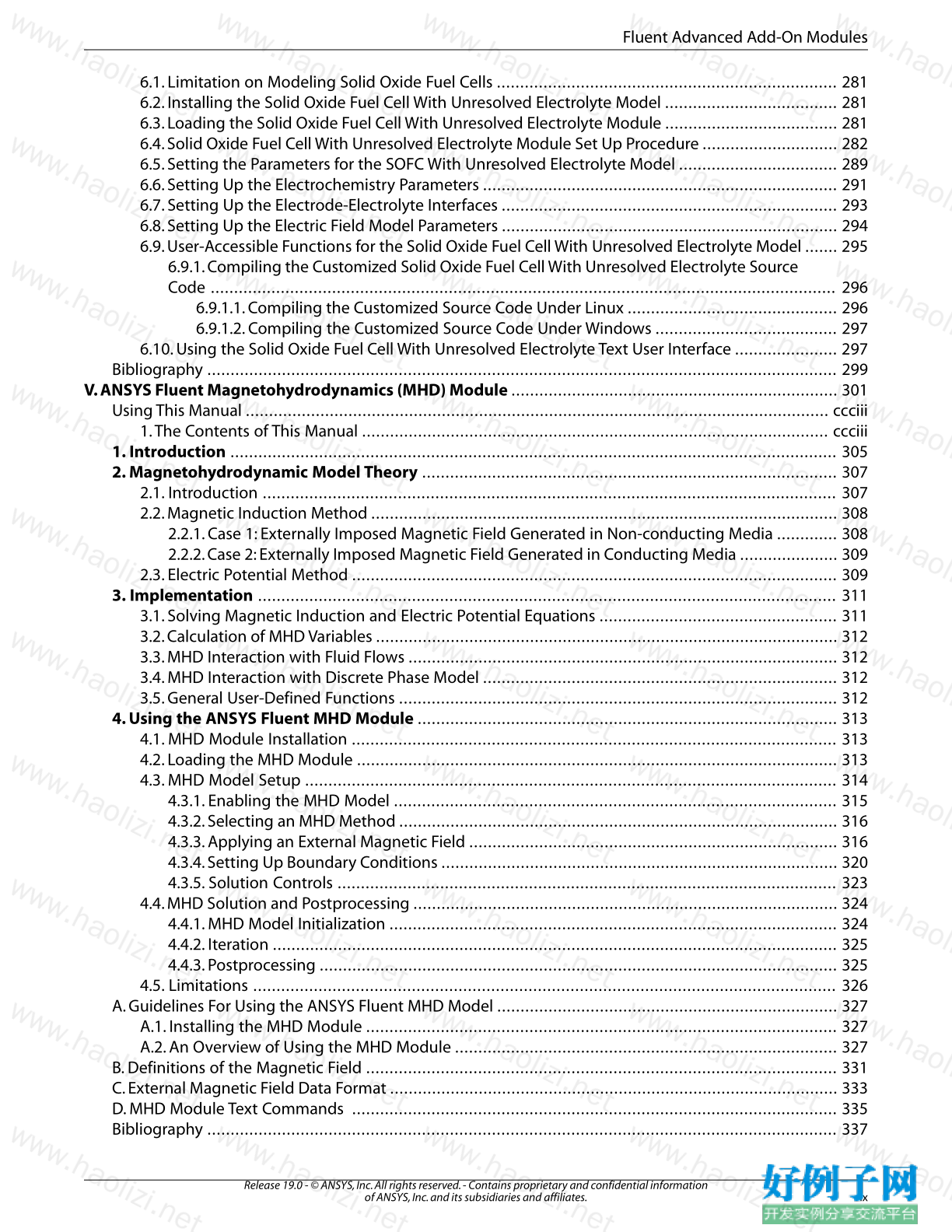
6.1. Limitation on Modeling Solid Oxide Fuel Cells ......................................................................... 281
6.2. Installing the Solid Oxide Fuel Cell With Unresolved Electrolyte Model ..................................... 281
6.3. Loading the Solid Oxide Fuel Cell With Unresolved Electrolyte Module ..................................... 281
6.4. Solid Oxide Fuel Cell With Unresolved Electrolyte Module Set Up Procedure ............................. 282
6.5. Setting the Parameters for the SOFC With Unresolved Electrolyte Model .................................. 289
6.6. Setting Up the Electrochemistry Parameters ............................................................................ 291
6.7. Setting Up the Electrode-Electrolyte Interfaces ........................................................................ 293
6.8. Setting Up the Electric Field Model Parameters ........................................................................ 294
6.9. User-Accessible Functions for the Solid Oxide Fuel Cell With Unresolved Electrolyte Model ....... 295
6.9.1. Compiling the Customized Solid Oxide Fuel Cell With Unresolved Electrolyte Source
Code ...................................................................................................................................... 296
6.9.1.1. Compiling the Customized Source Code Under Linux ............................................. 296
6.9.1.2. Compiling the Customized Source Code Under Windows ....................................... 297
6.10. Using the Solid Oxide Fuel Cell With Unresolved Electrolyte Text User Interface ...................... 297
Bibliography ....................................................................................................................................... 299
V. ANSYS Fluent Magnetohydrodynamics (MHD) Module ...................................................................... 301
Using This Manual ............................................................................................................................. ccciii
1.The Contents of This Manual .................................................................................................... ccciii
1. Introduction .................................................................................................................................. 305
2. Magnetohydrodynamic Model Theory ......................................................................................... 307
2.1. Introduction ........................................................................................................................... 307
2.2. Magnetic Induction Method .................................................................................................... 308
2.2.1. Case 1: Externally Imposed Magnetic Field Generated in Non-conducting Media ............. 308
2.2.2. Case 2: Externally Imposed Magnetic Field Generated in Conducting Media ..................... 309
2.3. Electric Potential Method ........................................................................................................ 309
3. Implementation ............................................................................................................................ 311
3.1. Solving Magnetic Induction and Electric Potential Equations ................................................... 311
3.2. Calculation of MHD Variables ................................................................................................... 312
3.3. MHD Interaction with Fluid Flows ............................................................................................ 312
3.4. MHD Interaction with Discrete Phase Model ............................................................................ 312
3.5. General User-Defined Functions .............................................................................................. 312
4. Using the ANSYS Fluent MHD Module .......................................................................................... 313
4.1. MHD Module Installation ........................................................................................................ 313
4.2. Loading the MHD Module ....................................................................................................... 313
4.3. MHD Model Setup .................................................................................................................. 314
4.3.1. Enabling the MHD Model ............................................................................................... 315
4.3.2. Selecting an MHD Method .............................................................................................. 316
4.3.3. Applying an External Magnetic Field ............................................................................... 316
4.3.4. Setting Up Boundary Conditions ..................................................................................... 320
4.3.5. Solution Controls ........................................................................................................... 323
4.4. MHD Solution and Postprocessing ........................................................................................... 324
4.4.1. MHD Model Initialization ................................................................................................ 324
4.4.2. Iteration ......................................................................................................................... 325
4.4.3. Postprocessing ............................................................................................................... 325
4.5. Limitations ............................................................................................................................. 326
A. Guidelines For Using the ANSYS Fluent MHD Model ......................................................................... 327
A.1. Installing the MHD Module ..................................................................................................... 327
A.2. An Overview of Using the MHD Module .................................................................................. 327
B. Definitions of the Magnetic Field ..................................................................................................... 331
C. External Magnetic Field Data Format ................................................................................................ 333
D. MHD Module Text Commands ........................................................................................................ 335
Bibliography ....................................................................................................................................... 337
ix
Release 19.0 - © ANSYS, Inc. All rights reserved. - Contains proprietary and confidential information
of ANSYS, Inc. and its subsidiaries and affiliates.
Fluent Advanced Add-On Modules
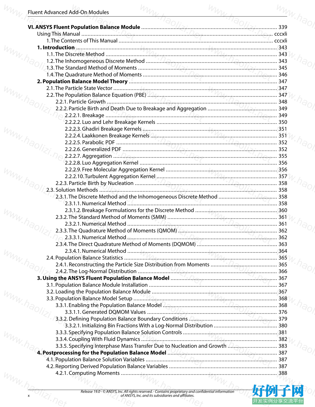
VI. ANSYS Fluent Population Balance Module ........................................................................................ 339
Using This Manual ............................................................................................................................ cccxli
1.The Contents of This Manual .................................................................................................... cccxli
1. Introduction .................................................................................................................................. 343
1.1.The Discrete Method ............................................................................................................... 343
1.2.The Inhomogeneous Discrete Method ..................................................................................... 343
1.3.The Standard Method of Moments .......................................................................................... 345
1.4.The Quadrature Method of Moments ....................................................................................... 346
2. Population Balance Model Theory ................................................................................................ 347
2.1.The Particle State Vector .......................................................................................................... 347
2.2.The Population Balance Equation (PBE) .................................................................................... 347
2.2.1. Particle Growth .............................................................................................................. 348
2.2.2. Particle Birth and Death Due to Breakage and Aggregation ............................................. 349
2.2.2.1. Breakage ............................................................................................................... 349
2.2.2.2. Luo and Lehr Breakage Kernels .............................................................................. 350
2.2.2.3. Ghadiri Breakage Kernels ....................................................................................... 351
2.2.2.4. Laakkonen Breakage Kernels .................................................................................. 351
2.2.2.5. Parabolic PDF ........................................................................................................ 352
2.2.2.6. Generalized PDF .................................................................................................... 352
2.2.2.7. Aggregation .......................................................................................................... 355
2.2.2.8. Luo Aggregation Kernel ......................................................................................... 356
2.2.2.9. Free Molecular Aggregation Kernel ........................................................................ 356
2.2.2.10.Turbulent Aggregation Kernel .............................................................................. 357
2.2.3. Particle Birth by Nucleation ............................................................................................ 358
2.3. Solution Methods ................................................................................................................... 358
2.3.1.The Discrete Method and the Inhomogeneous Discrete Method ...................................... 358
2.3.1.1. Numerical Method ................................................................................................. 358
2.3.1.2. Breakage Formulations for the Discrete Method ..................................................... 360
2.3.2.The Standard Method of Moments (SMM) ....................................................................... 361
2.3.2.1. Numerical Method ................................................................................................. 361
2.3.3.The Quadrature Method of Moments (QMOM) ................................................................ 362
2.3.3.1. Numerical Method ................................................................................................. 362
2.3.4.The Direct Quadrature Method of Moments (DQMOM) .................................................... 363
2.3.4.1. Numerical Method ................................................................................................. 364
2.4. Population Balance Statistics ................................................................................................... 365
2.4.1. Reconstructing the Particle Size Distribution from Moments ........................................... 365
2.4.2.The Log-Normal Distribution .......................................................................................... 366
3. Using the ANSYS Fluent Population Balance Model ..................................................................... 367
3.1. Population Balance Module Installation ................................................................................... 367
3.2. Loading the Population Balance Module ................................................................................. 367
3.3. Population Balance Model Setup ............................................................................................. 368
3.3.1. Enabling the Population Balance Model .......................................................................... 368
3.3.1.1. Generated DQMOM Values .................................................................................... 376
3.3.2. Defining Population Balance Boundary Conditions ......................................................... 379
3.3.2.1. Initializing Bin Fractions With a Log-Normal Distribution ......................................... 380
3.3.3. Specifying Population Balance Solution Controls ............................................................. 381
3.3.4. Coupling With Fluid Dynamics ........................................................................................ 382
3.3.5. Specifying Interphase Mass Transfer Due to Nucleation and Growth ................................ 383
4. Postprocessing for the Population Balance Model ....................................................................... 387
4.1. Population Balance Solution Variables ..................................................................................... 387
4.2. Reporting Derived Population Balance Variables ...................................................................... 387
4.2.1. Computing Moments ..................................................................................................... 388
Release 19.0 - © ANSYS, Inc. All rights reserved. - Contains proprietary and confidential information
of ANSYS, Inc. and its subsidiaries and affiliates. x
Fluent Advanced Add-On Modules
4.2.2. Displaying a Number Density Function ........................................................................... 388
5. UDFs for Population Balance Modeling ........................................................................................ 391
5.1. Population Balance Variables ................................................................................................... 391
5.2. Population Balance DEFINE Macros ....................................................................................... 391
5.2.1. DEFINE_PB_BREAK_UP_RATE_FREQ ....................................................................... 392
5.2.1.1. Usage .................................................................................................................... 392
5.2.1.2. Example ................................................................................................................ 392
5.2.2.DEFINE_PB_BREAK_UP_RATE_PDF .......................................................................... 393
5.2.2.1. Usage .................................................................................................................... 393
5.2.2.2. Example ................................................................................................................ 393
5.2.3.DEFINE_PB_COALESCENCE_RATE ............................................................................ 394
5.2.3.1. Usage .................................................................................................................... 394
5.2.3.2. Example ................................................................................................................ 394
5.2.4.DEFINE_PB_NUCLEATION_RATE .............................................................................. 395
5.2.4.1. Usage .................................................................................................................... 395
5.2.4.2. Example ................................................................................................................ 395
5.2.5.DEFINE_PB_GROWTH_RATE ....................................................................................... 396
5.2.5.1. Usage .................................................................................................................... 396
5.2.5.2. Example ................................................................................................................ 396
5.3. Hooking a Population Balance UDF to ANSYS Fluent ................................................................ 397
A.DEFINE_HET_RXN_RATE Macro ................................................................................................... 399
A.1. Description ............................................................................................................................ 399
A.2. Usage ..................................................................................................................................... 399
A.3. Example ................................................................................................................................. 400
A.4. Hooking a Heterogeneous Reaction Rate UDF to ANSYS Fluent ............................................... 401
Bibliography ....................................................................................................................................... 403
小贴士
感谢您为本站写下的评论,您的评论对其它用户来说具有重要的参考价值,所以请认真填写。
- 类似“顶”、“沙发”之类没有营养的文字,对勤劳贡献的楼主来说是令人沮丧的反馈信息。
- 相信您也不想看到一排文字/表情墙,所以请不要反馈意义不大的重复字符,也请尽量不要纯表情的回复。
- 提问之前请再仔细看一遍楼主的说明,或许是您遗漏了。
- 请勿到处挖坑绊人、招贴广告。既占空间让人厌烦,又没人会搭理,于人于己都无利。
关于好例子网
本站旨在为广大IT学习爱好者提供一个非营利性互相学习交流分享平台。本站所有资源都可以被免费获取学习研究。本站资源来自网友分享,对搜索内容的合法性不具有预见性、识别性、控制性,仅供学习研究,请务必在下载后24小时内给予删除,不得用于其他任何用途,否则后果自负。基于互联网的特殊性,平台无法对用户传输的作品、信息、内容的权属或合法性、安全性、合规性、真实性、科学性、完整权、有效性等进行实质审查;无论平台是否已进行审查,用户均应自行承担因其传输的作品、信息、内容而可能或已经产生的侵权或权属纠纷等法律责任。本站所有资源不代表本站的观点或立场,基于网友分享,根据中国法律《信息网络传播权保护条例》第二十二与二十三条之规定,若资源存在侵权或相关问题请联系本站客服人员,点此联系我们。关于更多版权及免责申明参见 版权及免责申明


网友评论
我要评论