实例介绍
【实例截图】
【核心代码】
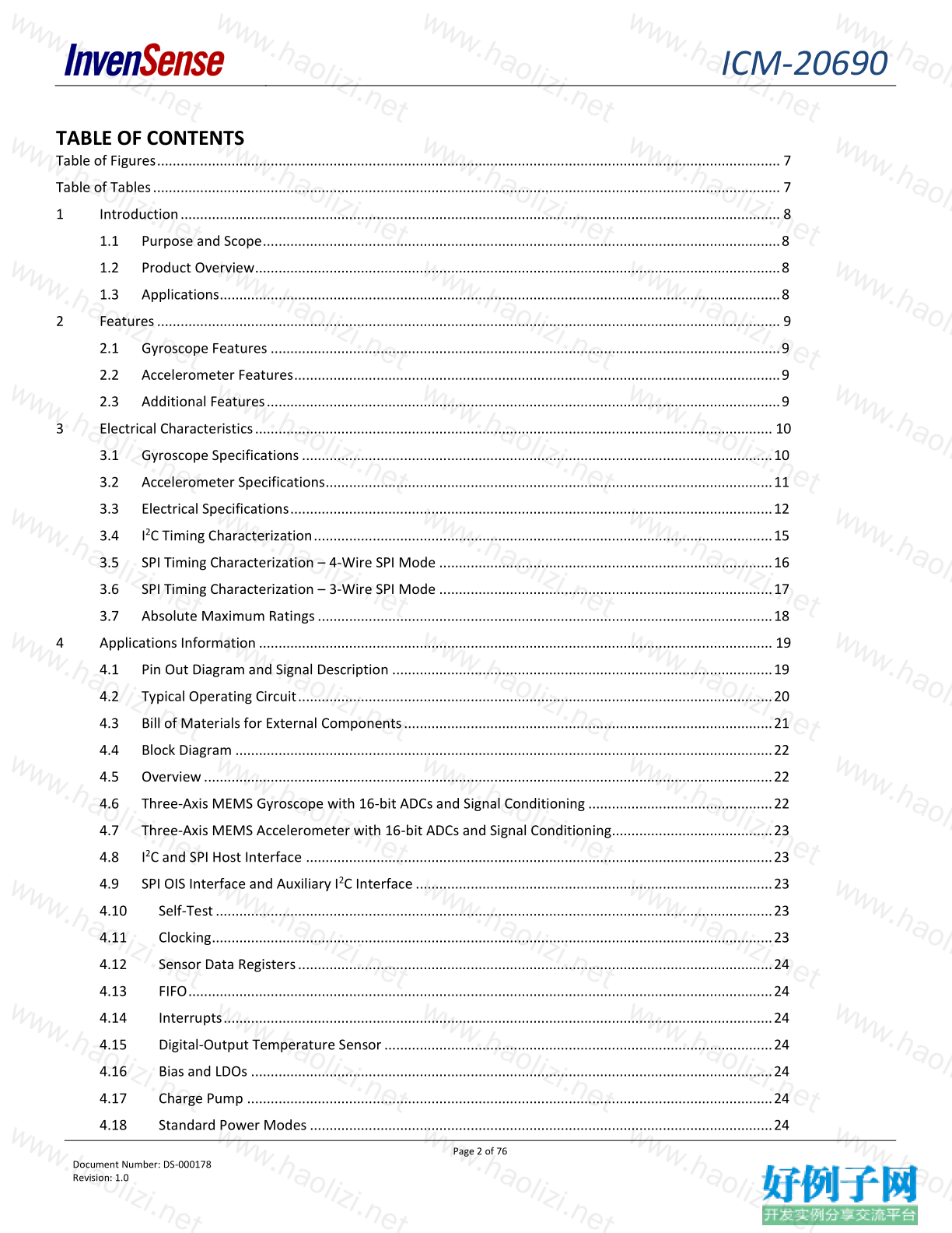
TABLE OF CONTENTS
Table of Figures ............................................................................................................................................................... 7
Table of Tables ................................................................................................................................................................ 7
1 Introduction ......................................................................................................................................................... 8
1.1 Purpose and Scope .................................................................................................................................... 8
1.2 Product Overview...................................................................................................................................... 8
1.3 Applications ............................................................................................................................................... 8
2 Features ............................................................................................................................................................... 9
2.1 Gyroscope Features .................................................................................................................................. 9
2.2 Accelerometer Features ............................................................................................................................ 9
2.3 Additional Features ................................................................................................................................... 9
3 Electrical Characteristics .................................................................................................................................... 10
3.1 Gyroscope Specifications ........................................................................................................................ 10
3.2 Accelerometer Specifications .................................................................................................................. 11
3.3 Electrical Specifications ........................................................................................................................... 12
3.4 I 2 C Timing Characterization ..................................................................................................................... 15
3.5 SPI Timing Characterization – 4-Wire SPI Mode ..................................................................................... 16
3.6 SPI Timing Characterization – 3-Wire SPI Mode ..................................................................................... 17
3.7 Absolute Maximum Ratings .................................................................................................................... 18
4 Applications Information ................................................................................................................................... 19
4.1 Pin Out Diagram and Signal Description ................................................................................................. 19
4.2 Typical Operating Circuit ......................................................................................................................... 20
4.3 Bill of Materials for External Components .............................................................................................. 21
4.4 Block Diagram ......................................................................................................................................... 22
4.5 Overview ................................................................................................................................................. 22
4.6 Three-Axis MEMS Gyroscope with 16-bit ADCs and Signal Conditioning ............................................... 22
4.7 Three-Axis MEMS Accelerometer with 16-bit ADCs and Signal Conditioning ......................................... 23
4.8 I 2 C and SPI Host Interface ....................................................................................................................... 23
4.9 SPI OIS Interface and Auxiliary I 2 C Interface ........................................................................................... 23
4.10 Self-Test .............................................................................................................................................. 23
4.11 Clocking ............................................................................................................................................... 23
4.12 Sensor Data Registers ......................................................................................................................... 24
4.13 FIFO ..................................................................................................................................................... 24
4.14 Interrupts ............................................................................................................................................ 24
4.15 Digital-Output Temperature Sensor ................................................................................................... 24
4.16 Bias and LDOs ..................................................................................................................................... 24
4.17 Charge Pump ...................................................................................................................................... 24
4.18 Standard Power Modes ...................................................................................................................... 24
ICM-20690
Page 3 of 76
Document Number: DS-000178
Revision: 1.0
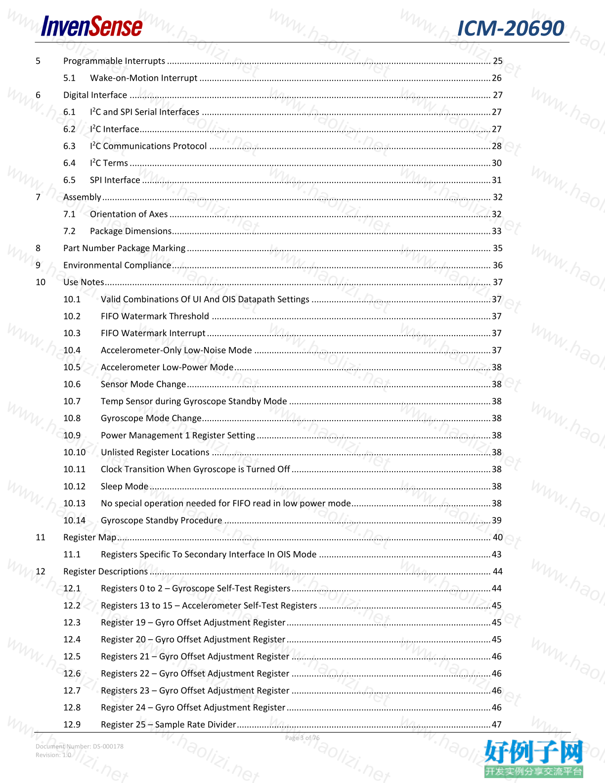
5 Programmable Interrupts .................................................................................................................................. 25
5.1 Wake-on-Motion Interrupt ..................................................................................................................... 26
6 Digital Interface ................................................................................................................................................. 27
6.1 I 2 C and SPI Serial Interfaces .................................................................................................................... 27
6.2 I 2 C Interface ............................................................................................................................................. 27
6.3 I 2 C Communications Protocol ................................................................................................................. 28
6.4 I 2 C Terms ................................................................................................................................................. 30
6.5 SPI Interface ............................................................................................................................................ 31
7 Assembly ............................................................................................................................................................ 32
7.1 Orientation of Axes ................................................................................................................................. 32
7.2 Package Dimensions ................................................................................................................................ 33
8 Part Number Package Marking .......................................................................................................................... 35
9 Environmental Compliance ................................................................................................................................ 36
10 Use Notes ........................................................................................................................................................... 37
10.1 Valid Combinations Of UI And OIS Datapath Settings ........................................................................ 37
10.2 FIFO Watermark Threshold ................................................................................................................ 37
10.3 FIFO Watermark Interrupt .................................................................................................................. 37
10.4 Accelerometer-Only Low-Noise Mode ............................................................................................... 37
10.5 Accelerometer Low-Power Mode ....................................................................................................... 38
10.6 Sensor Mode Change .......................................................................................................................... 38
10.7 Temp Sensor during Gyroscope Standby Mode ................................................................................. 38
10.8 Gyroscope Mode Change.................................................................................................................... 38
10.9 Power Management 1 Register Setting .............................................................................................. 38
10.10 Unlisted Register Locations ................................................................................................................ 38
10.11 Clock Transition When Gyroscope is Turned Off ................................................................................ 38
10.12 Sleep Mode ......................................................................................................................................... 38
10.13 No special operation needed for FIFO read in low power mode........................................................ 38
10.14 Gyroscope Standby Procedure ........................................................................................................... 39
11 Register Map ...................................................................................................................................................... 40
11.1 Registers Specific To Secondary Interface In OIS Mode ..................................................................... 43
12 Register Descriptions ......................................................................................................................................... 44
12.1 Registers 0 to 2 – Gyroscope Self-Test Registers ................................................................................ 44
12.2 Registers 13 to 15 – Accelerometer Self-Test Registers ..................................................................... 45
12.3 Register 19 – Gyro Offset Adjustment Register .................................................................................. 45
12.4 Register 20 – Gyro Offset Adjustment Register .................................................................................. 45
12.5 Registers 21 – Gyro Offset Adjustment Register ................................................................................ 46
12.6 Registers 22 – Gyro Offset Adjustment Register ................................................................................ 46
12.7 Registers 23 – Gyro Offset Adjustment Register ................................................................................ 46
12.8 Register 24 – Gyro Offset Adjustment Register .................................................................................. 46
12.9 Register 25 – Sample Rate Divider ...................................................................................................... 47
ICM-20690
Page 4 of 76
Document Number: DS-000178
Revision: 1.0
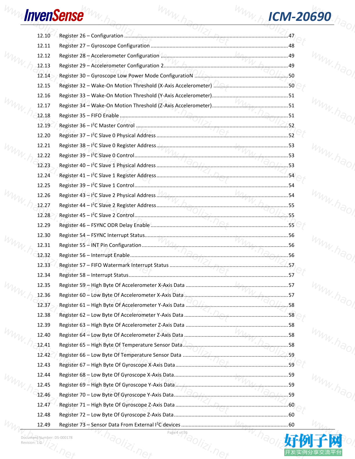
12.10 Register 26 – Configuration ................................................................................................................ 47
12.11 Register 27 – Gyroscope Configuration .............................................................................................. 48
12.12 Register 28 – Accelerometer Configuration ....................................................................................... 49
12.13 Register 29 – Accelerometer Configuration 2..................................................................................... 49
12.14 Register 30 – Gyroscope Low Power Mode ConfiguratioN ................................................................ 50
12.15 Register 32 – Wake-On Motion Threshold (X-Axis Accelerometer) ................................................... 50
12.16 Register 33 – Wake-On Motion Threshold (Y-Axis Accelerometer) .................................................... 51
12.17 Register 34 – Wake-On Motion Threshold (Z-Axis Accelerometer) .................................................... 51
12.18 Register 35 – FIFO Enable ................................................................................................................... 51
12.19 Register 36 – I 2 C Master Control ........................................................................................................ 52
12.20 Register 37 – I 2 C Slave 0 Physical Address .......................................................................................... 52
12.21 Register 38 – I 2 C Slave 0 Register Address .......................................................................................... 53
12.22 Register 39 – I 2 C Slave 0 Control ......................................................................................................... 53
12.23 Register 40 – I 2 C Slave 1 Physical Address .......................................................................................... 53
12.24 Register 41 – I 2 C Slave 1 Register Address .......................................................................................... 54
12.25 Register 39 – I 2 C Slave 1 Control ......................................................................................................... 54
12.26 Register 43 – I 2 C Slave 2 Physical Address .......................................................................................... 54
12.27 Register 44 – I 2 C Slave 2 Register Address .......................................................................................... 55
12.28 Register 45 – I 2 C Slave 2 Control ......................................................................................................... 55
12.29 Register 46 – FSYNC ODR Delay Enable .............................................................................................. 55
12.30 Register 54 – FSYNC Interrupt Status.................................................................................................. 56
12.31 Register 55 – INT Pin Configuration .................................................................................................... 56
12.32 Register 56 – Interrupt Enable ............................................................................................................ 56
12.33 Register 57 – FIFO Watermark Interrupt Status ................................................................................. 57
12.34 Register 58 – Interrupt Status ............................................................................................................. 57
12.35 Register 59 – High Byte Of Accelerometer X-Axis Data ...................................................................... 57
12.36 Register 60 – Low Byte Of Accelerometer X-Axis Data ....................................................................... 57
12.37 Register 61 – High Byte Of Accelerometer Y-Axis Data ...................................................................... 58
12.38 Register 62 – Low Byte Of Accelerometer Y-Axis Data ....................................................................... 58
12.39 Register 63 – High Byte Of Accelerometer Z-Axis Data ...................................................................... 58
12.40 Register 64 – Low Byte Of Accelerometer Z-Axis Data ....................................................................... 58
12.41 Register 65 – High Byte Of Temperature Sensor Data ........................................................................ 58
12.42 Register 66 – Low Byte Of Temperature Sensor Data ........................................................................ 59
12.43 Register 67 – High Byte Of Gyroscope X-Axis Data ............................................................................. 59
12.44 Register 68 – Low Byte Of Gyroscope X-Axis Data.............................................................................. 59
12.45 Register 69 – High Byte Of Gyroscope Y-Axis Data ............................................................................. 59
12.46 Register 70 – Low Byte Of Gyroscope Y-Axis Data .............................................................................. 59
12.47 Register 71 – High Byte Of Gyroscope Z-Axis Data ............................................................................. 60
12.48 Register 72 – Low Byte Of Gyroscope Z-Axis Data .............................................................................. 60
12.49 Register 73 – Sensor Data From External I 2 C devices ......................................................................... 60
ICM-20690
Page 5 of 76
Document Number: DS-000178
Revision: 1.0
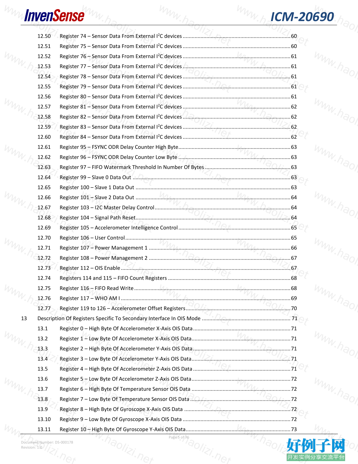
12.50 Register 74 – Sensor Data From External I 2 C devices ......................................................................... 60
12.51 Register 75 – Sensor Data From External I 2 C devices ......................................................................... 60
12.52 Register 76 – Sensor Data From External I 2 C devices ......................................................................... 61
12.53 Register 77 – Sensor Data From External I 2 C devices ......................................................................... 61
12.54 Register 78 – Sensor Data From External I 2 C devices ......................................................................... 61
12.55 Register 79 – Sensor Data From External I 2 C devices ......................................................................... 61
12.56 Register 80 – Sensor Data From External I 2 C devices ......................................................................... 61
12.57 Register 81 – Sensor Data From External I 2 C devices ......................................................................... 62
12.58 Register 82 – Sensor Data From External I 2 C devices ......................................................................... 62
12.59 Register 83 – Sensor Data From External I 2 C devices ......................................................................... 62
12.60 Register 84 – Sensor Data From External I 2 C devices ......................................................................... 62
12.61 Register 95 – FSYNC ODR Delay Counter High Byte ............................................................................ 63
12.62 Register 96 – FSYNC ODR Delay Counter Low Byte ............................................................................ 63
12.63 Register 97 – FIFO Watermark Threshold In Number Of Bytes .......................................................... 63
12.64 Register 99 – Slave 0 Data Out ........................................................................................................... 63
12.65 Register 100 – Slave 1 Data Out ......................................................................................................... 63
12.66 Register 101 – Slave 2 Data Out ......................................................................................................... 64
12.67 Register 103 – I2C Master Delay Control ............................................................................................ 64
12.68 Register 104 – Signal Path Reset ......................................................................................................... 64
12.69 Register 105 – Accelerometer Intelligence Control ............................................................................ 65
12.70 Register 106 – User Control ................................................................................................................ 65
12.71 Register 107 – Power Management 1 ................................................................................................ 66
12.72 Register 108 – Power Management 2 ................................................................................................ 67
12.73 Register 112 – OIS Enable ................................................................................................................... 67
12.74 Registers 114 and 115 – FIFO Count Registers ................................................................................... 68
12.75 Register 116 – FIFO Read Write .......................................................................................................... 68
12.76 Register 117 – WHO AM I ................................................................................................................... 69
12.77 Register 119 to 126 – Accelerometer Offset Registers ....................................................................... 70
13 Description Of Registers Specific To Secondary Interface In OIS Mode ............................................................ 71
13.1 Register 0 – High Byte Of Accelerometer X-Axis OIS Data .................................................................. 71
13.2 Register 1 – Low Byte Of Accelerometer X-Axis OIS Data................................................................... 71
13.3 Register 2 – High Byte Of Accelerometer Y-Axis OIS Data .................................................................. 71
13.4 Register 3 – Low Byte Of Accelerometer Y-Axis OIS Data ................................................................... 71
13.5 Register 4 – High Byte Of Accelerometer Z-Axis OIS Data .................................................................. 71
13.6 Register 5 – Low Byte Of Accelerometer Z-Axis OIS Data ................................................................... 72
13.7 Register 6 – High Byte Of Temperature Sensor OIS Data ................................................................... 72
13.8 Register 7 – Low Byte Of Temperature Sensor OIS Data .................................................................... 72
13.9 Register 8 – High Byte Of Gyroscope X-Axis OIS Data ........................................................................ 72
13.10 Register 9 – Low Byte Of Gyroscope X-Axis OIS Data ......................................................................... 72
13.11 Register 10 – High Byte Of Gyroscope Y-Axis OIS Data ....................................................................... 73
ICM-20690
Page 6 of 76
Document Number: DS-000178
Revision: 1.0
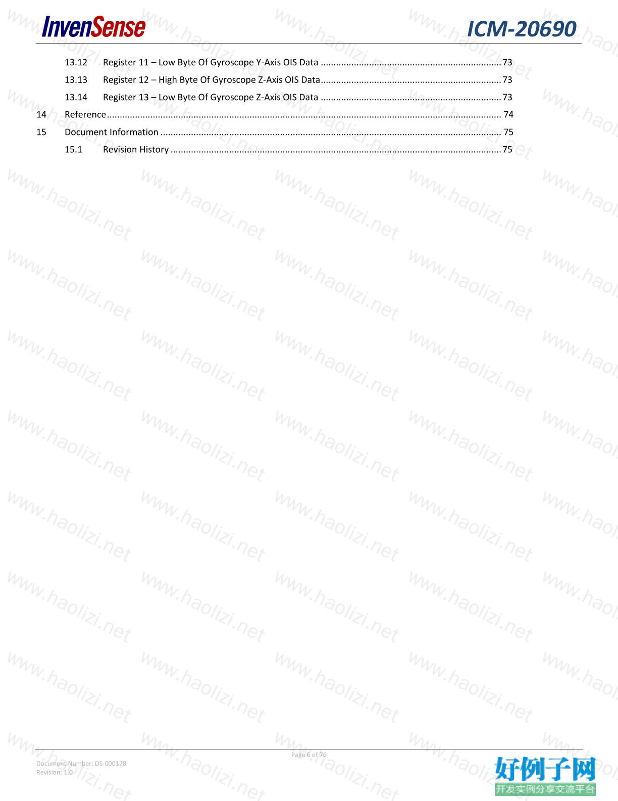
13.12 Register 11 – Low Byte Of Gyroscope Y-Axis OIS Data ....................................................................... 73
13.13 Register 12 – High Byte Of Gyroscope Z-Axis OIS Data ....................................................................... 73
13.14 Register 13 – Low Byte Of Gyroscope Z-Axis OIS Data ....................................................................... 73
14 Reference ........................................................................................................................................................... 74
15 Document Information ...................................................................................................................................... 75
15.1 Revision History .................................................................................................................................. 75
ICM-20690
Page 7 of 76
Document Number: DS-000178
Revision: 1.0
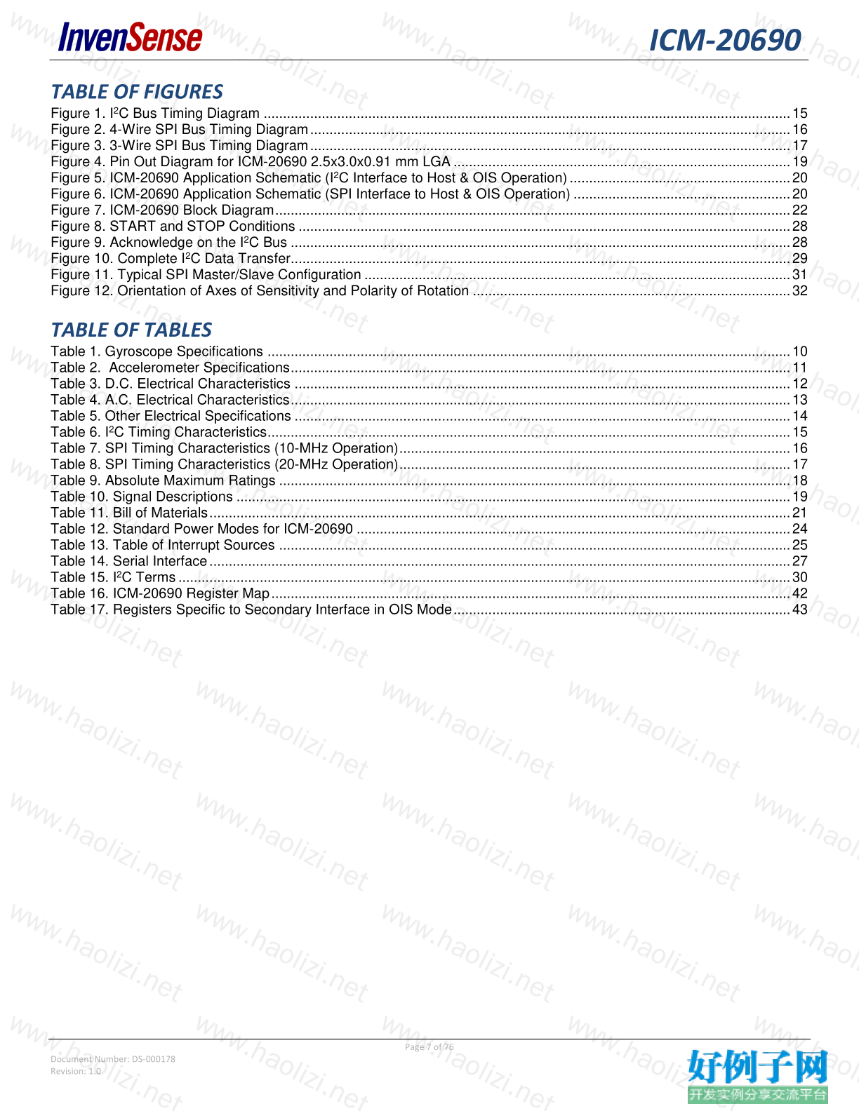
TABLE OF FIGURES
Figure 1. I 2 C Bus Timing Diagram ........................................................................................................................................ 15
Figure 2. 4-Wire SPI Bus Timing Diagram ............................................................................................................................ 16
Figure 3. 3-Wire SPI Bus Timing Diagram ............................................................................................................................ 17
Figure 4. Pin Out Diagram for ICM-20690 2.5x3.0x0.91 mm LGA ....................................................................................... 19
Figure 5. ICM-20690 Application Schematic (I 2 C Interface to Host & OIS Operation) ......................................................... 20
Figure 6. ICM-20690 Application Schematic (SPI Interface to Host & OIS Operation) ........................................................ 20
Figure 7. ICM-20690 Block Diagram ..................................................................................................................................... 22
Figure 8. START and STOP Conditions ............................................................................................................................... 28
Figure 9. Acknowledge on the I 2 C Bus ................................................................................................................................. 28
Figure 10. Complete I 2 C Data Transfer ................................................................................................................................. 29
Figure 11. Typical SPI Master/Slave Configuration .............................................................................................................. 31
Figure 12. Orientation of Axes of Sensitivity and Polarity of Rotation .................................................................................. 32
TABLE OF TABLES
Table 1. Gyroscope Specifications ....................................................................................................................................... 10
Table 2. Accelerometer Specifications ................................................................................................................................. 11
Table 3. D.C. Electrical Characteristics ................................................................................................................................ 12
Table 4. A.C. Electrical Characteristics ................................................................................................................................. 13
Table 5. Other Electrical Specifications ................................................................................................................................ 14
Table 6. I 2 C Timing Characteristics ....................................................................................................................................... 15
Table 7. SPI Timing Characteristics (10-MHz Operation) ..................................................................................................... 16
Table 8. SPI Timing Characteristics (20-MHz Operation) ..................................................................................................... 17
Table 9. Absolute Maximum Ratings .................................................................................................................................... 18
Table 10. Signal Descriptions ............................................................................................................................................... 19
Table 11. Bill of Materials ...................................................................................................................................................... 21
Table 12. Standard Power Modes for ICM-20690 ................................................................................................................ 24
Table 13. Table of Interrupt Sources .................................................................................................................................... 25
Table 14. Serial Interface ...................................................................................................................................................... 27
Table 15. I 2 C Terms .............................................................................................................................................................. 30
Table 16. ICM-20690 Register Map ...................................................................................................................................... 42
Table 17. Registers Specific to Secondary Interface in OIS Mode ....................................................................................... 43
相关软件
小贴士
感谢您为本站写下的评论,您的评论对其它用户来说具有重要的参考价值,所以请认真填写。
- 类似“顶”、“沙发”之类没有营养的文字,对勤劳贡献的楼主来说是令人沮丧的反馈信息。
- 相信您也不想看到一排文字/表情墙,所以请不要反馈意义不大的重复字符,也请尽量不要纯表情的回复。
- 提问之前请再仔细看一遍楼主的说明,或许是您遗漏了。
- 请勿到处挖坑绊人、招贴广告。既占空间让人厌烦,又没人会搭理,于人于己都无利。
关于好例子网
本站旨在为广大IT学习爱好者提供一个非营利性互相学习交流分享平台。本站所有资源都可以被免费获取学习研究。本站资源来自网友分享,对搜索内容的合法性不具有预见性、识别性、控制性,仅供学习研究,请务必在下载后24小时内给予删除,不得用于其他任何用途,否则后果自负。基于互联网的特殊性,平台无法对用户传输的作品、信息、内容的权属或合法性、安全性、合规性、真实性、科学性、完整权、有效性等进行实质审查;无论平台是否已进行审查,用户均应自行承担因其传输的作品、信息、内容而可能或已经产生的侵权或权属纠纷等法律责任。本站所有资源不代表本站的观点或立场,基于网友分享,根据中国法律《信息网络传播权保护条例》第二十二与二十三条之规定,若资源存在侵权或相关问题请联系本站客服人员,点此联系我们。关于更多版权及免责申明参见 版权及免责申明


网友评论
我要评论