实例介绍
【实例简介】MIPI-DSI-Specification
【实例截图】
【实例截图】

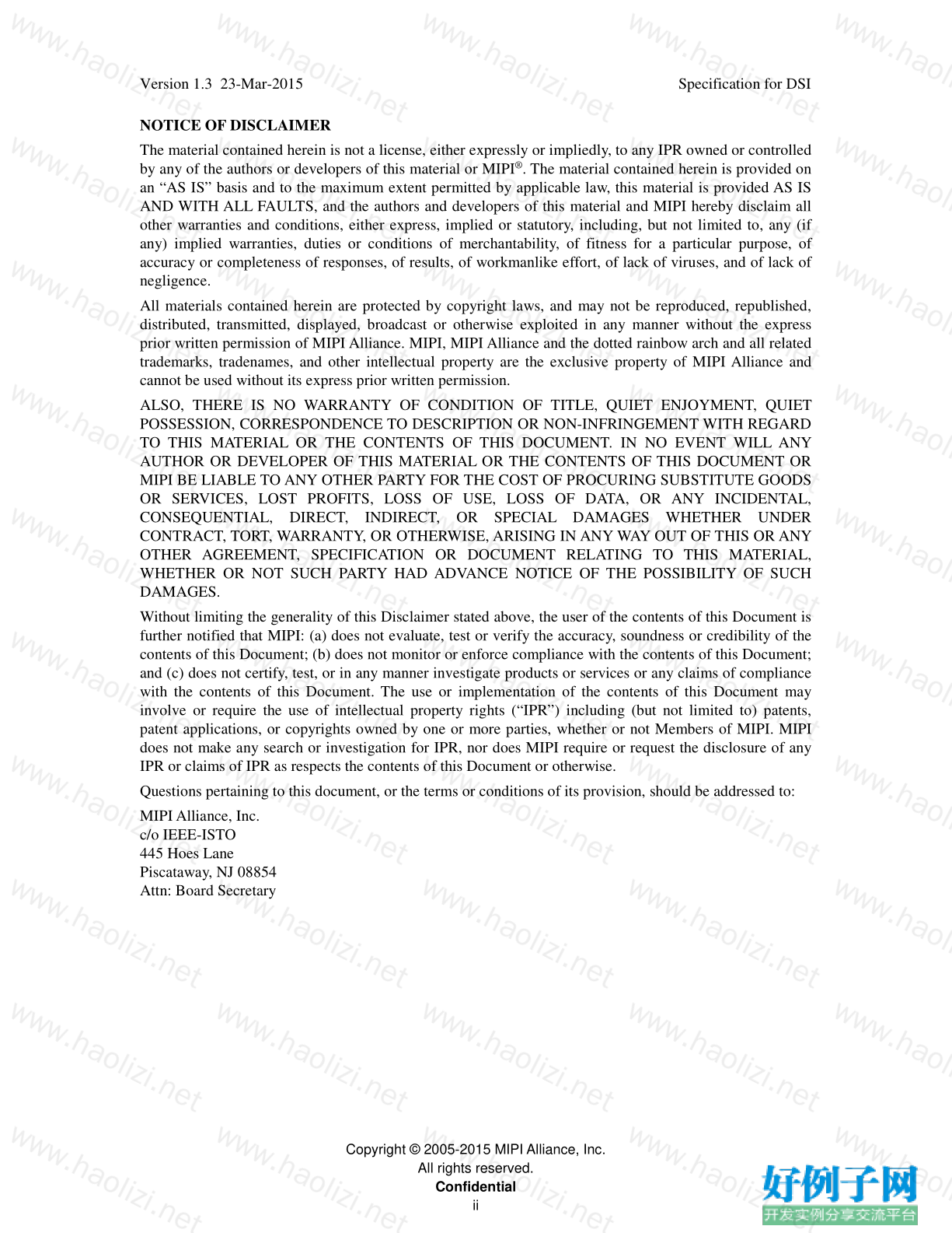
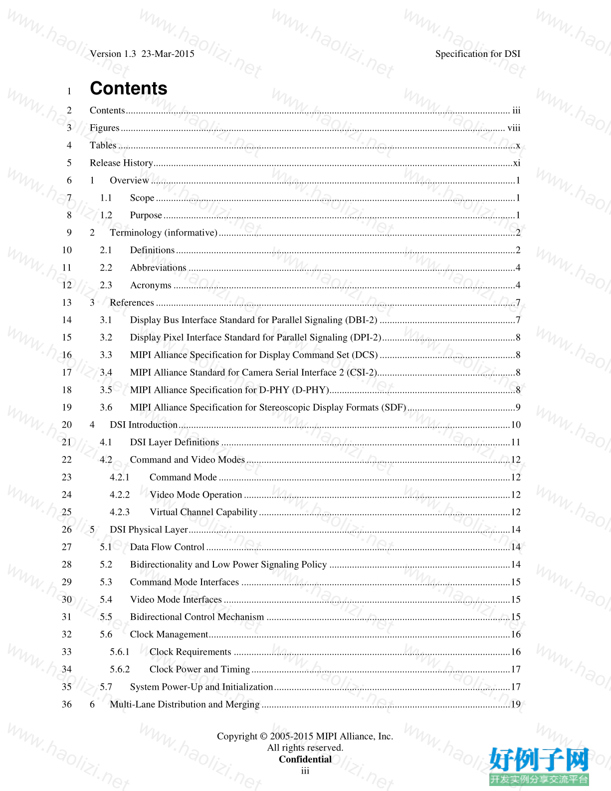
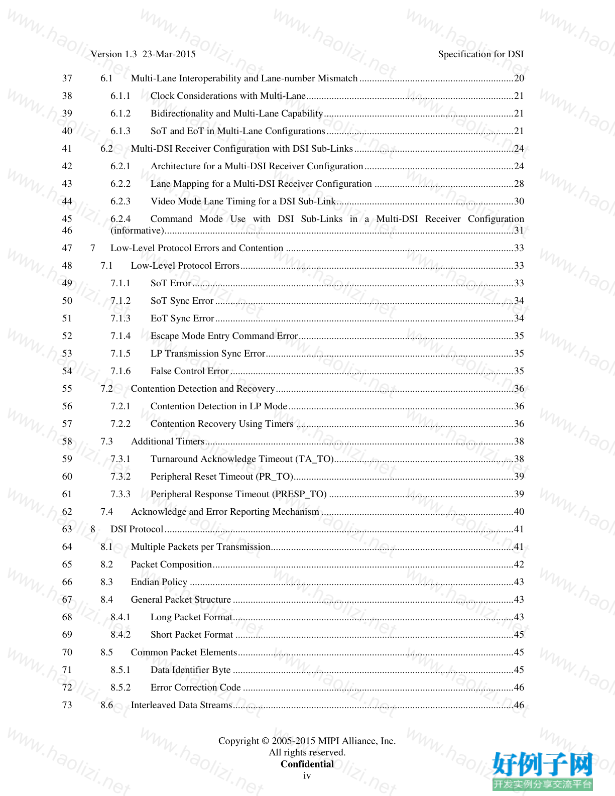
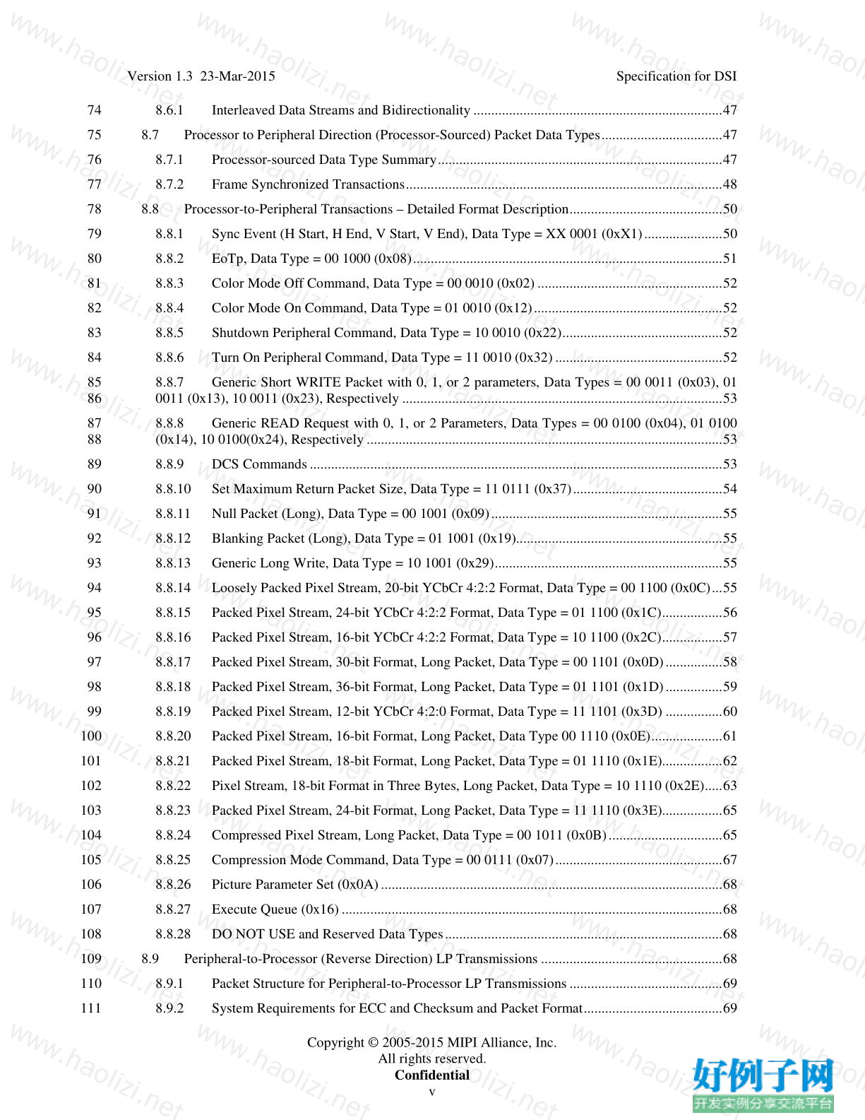
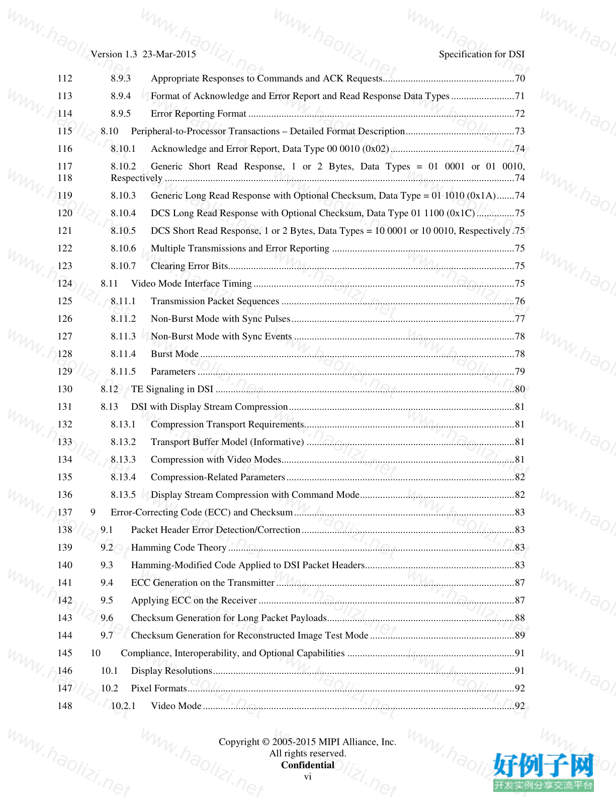
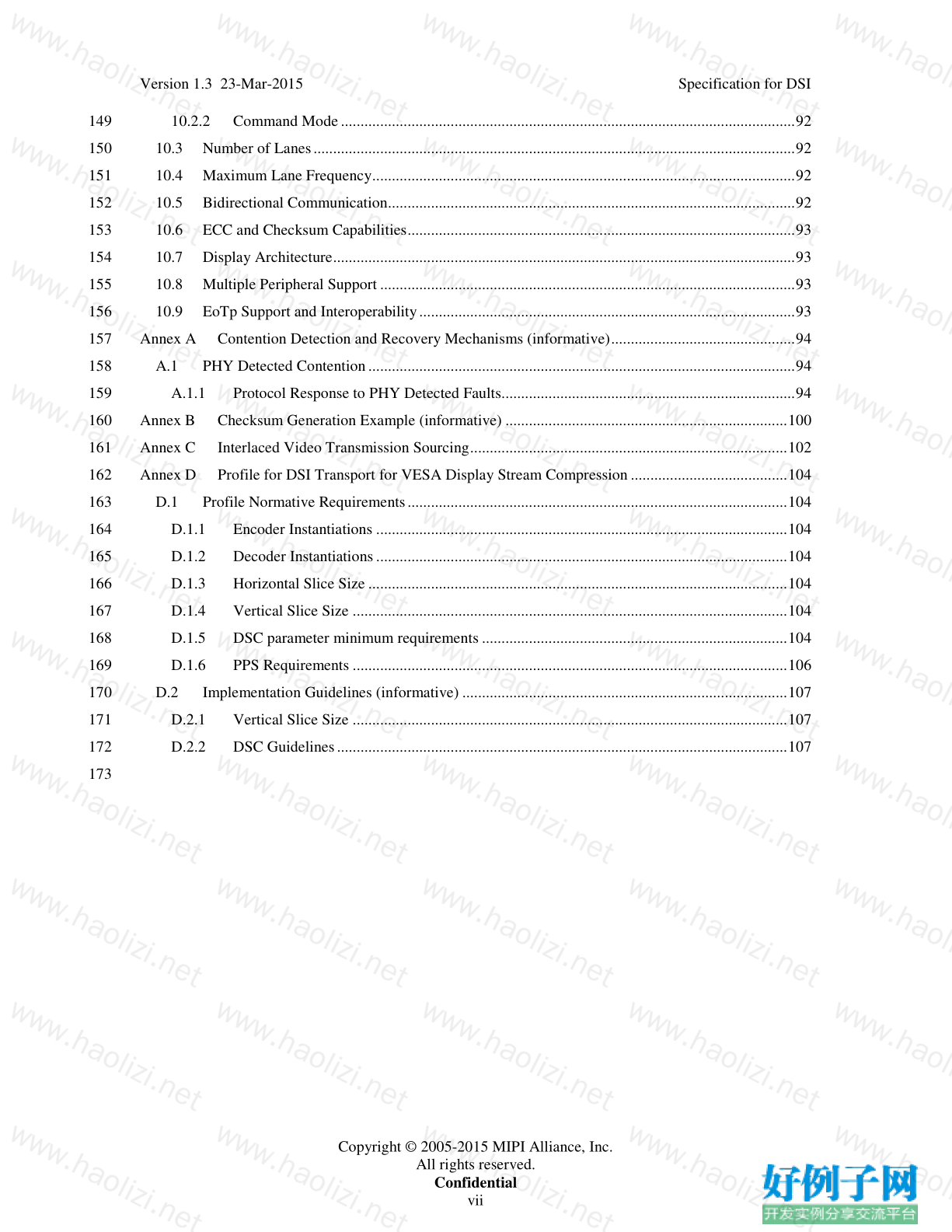
【核心代码】
Contents
Contents......................................................................................................................................................... iii
2
Figures......................................................................................................................................................... viii
3
Tables..............................................................................................................................................................x
4
Release History...............................................................................................................................................xi
5
1 Overview .................................................................................................................................................1
6
1.1
Scope ...............................................................................................................................................1
7
1.2
Purpose ............................................................................................................................................1
8
2 Terminology (informative)......................................................................................................................2
9
2.1
Definitions.......................................................................................................................................2
10
2.2
Abbreviations ..................................................................................................................................4
11
2.3
Acronyms ........................................................................................................................................4
12
3 References...............................................................................................................................................7
13
3.1
Display Bus Interface Standard for Parallel Signaling (DBI-2) ......................................................7
14
3.2
Display Pixel Interface Standard for Parallel Signaling (DPI-2).....................................................8
15
3.3
MIPI Alliance Specification for Display Command Set (DCS) ......................................................8
16
3.4
MIPI Alliance Standard for Camera Serial Interface 2 (CSI-2).......................................................8
17
3.5
MIPI Alliance Specification for D-PHY (D-PHY)..........................................................................8
18
3.6
MIPI Alliance Specification for Stereoscopic Display Formats (SDF)...........................................9
19
4 DSI Introduction....................................................................................................................................10
20
4.1
DSI Layer Definitions ...................................................................................................................11
21
4.2
Command and Video Modes.........................................................................................................12
22
4.2.1
Command Mode ....................................................................................................................12
23
4.2.2
Video Mode Operation ..........................................................................................................12
24
4.2.3
Virtual Channel Capability ....................................................................................................12
25
5 DSI Physical Layer................................................................................................................................14
26
5.1
Data Flow Control .........................................................................................................................14
27
5.2
Bidirectionality and Low Power Signaling Policy ........................................................................14
28
5.3
Command Mode Interfaces ...........................................................................................................15
29
5.4
Video Mode Interfaces..................................................................................................................15
30
5.5
Bidirectional Control Mechanism .................................................................................................15
31
5.6
Clock Management........................................................................................................................16
32
5.6.1
Clock Requirements ..............................................................................................................16
33
5.6.2
Clock Power and Timing .......................................................................................................17
34
5.7
System Power-Up and Initialization..............................................................................................17
35
6 Multi-Lane Distribution and Merging ...................................................................................................19
36
Copyright © 2005-2015 MIPI Alliance, Inc.
All rights reserved.
Confidential
iiiVersion 1.3 23-Mar-2015
Specification for DSI
6.1
Multi-Lane Interoperability and Lane-number Mismatch .............................................................20
37
6.1.1
Clock Considerations with Multi-Lane..................................................................................21
38
6.1.2
Bidirectionality and Multi-Lane Capability...........................................................................21
39
6.1.3
SoT and EoT in Multi-Lane Configurations..........................................................................21
40
6.2
Multi-DSI Receiver Configuration with DSI Sub-Links...............................................................24
41
6.2.1
Architecture for a Multi-DSI Receiver Configuration...........................................................24
42
6.2.2
Lane Mapping for a Multi-DSI Receiver Configuration .......................................................28
43
6.2.3
Video Mode Lane Timing for a DSI Sub-Link......................................................................30
44
6.2.4
Command Mode Use with DSI Sub-Links in a Multi-DSI Receiver Configuration
45
(informative)..........................................................................................................................................31
46
7 Low-Level Protocol Errors and Contention ..........................................................................................33
47
7.1
Low-Level Protocol Errors............................................................................................................33
48
7.1.1
SoT Error...............................................................................................................................33
49
7.1.2
SoT Sync Error......................................................................................................................34
50
7.1.3
EoT Sync Error......................................................................................................................34
51
7.1.4
Escape Mode Entry Command Error.....................................................................................35
52
7.1.5
LP Transmission Sync Error..................................................................................................35
53
7.1.6
False Control Error................................................................................................................35
54
7.2
Contention Detection and Recovery..............................................................................................36
55
7.2.1
Contention Detection in LP Mode.........................................................................................36
56
7.2.2
Contention Recovery Using Timers ......................................................................................36
57
7.3
Additional Timers..........................................................................................................................38
58
7.3.1
Turnaround Acknowledge Timeout (TA_TO).......................................................................38
59
7.3.2
Peripheral Reset Timeout (PR_TO).......................................................................................39
60
7.3.3
Peripheral Response Timeout (PRESP_TO) .........................................................................39
61
7.4
Acknowledge and Error Reporting Mechanism ............................................................................40
62
8 DSI Protocol..........................................................................................................................................41
63
8.1
Multiple Packets per Transmission................................................................................................41
64
8.2
Packet Composition.......................................................................................................................42
65
8.3
Endian Policy ................................................................................................................................43
66
8.4
General Packet Structure ...............................................................................................................43
67
8.4.1
Long Packet Format...............................................................................................................43
68
8.4.2
Short Packet Format ..............................................................................................................45
69
8.5
Common Packet Elements.............................................................................................................45
70
8.5.1
Data Identifier Byte ...............................................................................................................45
71
8.5.2
Error Correction Code ...........................................................................................................46
72
8.6
Interleaved Data Streams...............................................................................................................46
73
Copyright © 2005-2015 MIPI Alliance, Inc.
All rights reserved.
Confidential
ivVersion 1.3 23-Mar-2015
Specification for DSI
8.6.1
Interleaved Data Streams and Bidirectionality ......................................................................47
74
8.7
Processor to Peripheral Direction (Processor-Sourced) Packet Data Types..................................47
75
8.7.1
Processor-sourced Data Type Summary................................................................................47
76
8.7.2
Frame Synchronized Transactions.........................................................................................48
77
8.8
Processor-to-Peripheral Transactions – Detailed Format Description...........................................50
78
8.8.1
Sync Event (H Start, H End, V Start, V End), Data Type = XX 0001 (0xX1)......................50
79
8.8.2
EoTp, Data Type = 00 1000 (0x08).......................................................................................51
80
8.8.3
Color Mode Off Command, Data Type = 00 0010 (0x02) ....................................................52
81
8.8.4
Color Mode On Command, Data Type = 01 0010 (0x12).....................................................52
82
8.8.5
Shutdown Peripheral Command, Data Type = 10 0010 (0x22).............................................52
83
8.8.6
Turn On Peripheral Command, Data Type = 11 0010 (0x32) ...............................................52
84
8.8.7
Generic Short WRITE Packet with 0, 1, or 2 parameters, Data Types = 00 0011 (0x03), 01
85
0011 (0x13), 10 0011 (0x23), Respectively ..........................................................................................53
86
8.8.8
Generic READ Request with 0, 1, or 2 Parameters, Data Types = 00 0100 (0x04), 01 0100
87
(0x14), 10 0100(0x24), Respectively ....................................................................................................53
88
8.8.9
DCS Commands....................................................................................................................53
89
8.8.10 Set Maximum Return Packet Size, Data Type = 11 0111 (0x37)..........................................54
90
8.8.11 Null Packet (Long), Data Type = 00 1001 (0x09).................................................................55
91
8.8.12 Blanking Packet (Long), Data Type = 01 1001 (0x19)..........................................................55
92
8.8.13 Generic Long Write, Data Type = 10 1001 (0x29)................................................................55
93
8.8.14 Loosely Packed Pixel Stream, 20-bit YCbCr 4:2:2 Format, Data Type = 00 1100 (0x0C)...55
94
8.8.15 Packed Pixel Stream, 24-bit YCbCr 4:2:2 Format, Data Type = 01 1100 (0x1C).................56
95
8.8.16 Packed Pixel Stream, 16-bit YCbCr 4:2:2 Format, Data Type = 10 1100 (0x2C).................57
96
8.8.17 Packed Pixel Stream, 30-bit Format, Long Packet, Data Type = 00 1101 (0x0D)................58
97
8.8.18 Packed Pixel Stream, 36-bit Format, Long Packet, Data Type = 01 1101 (0x1D)................59
98
8.8.19 Packed Pixel Stream, 12-bit YCbCr 4:2:0 Format, Data Type = 11 1101 (0x3D) ................60
99
8.8.20 Packed Pixel Stream, 16-bit Format, Long Packet, Data Type 00 1110 (0x0E)....................61
100
8.8.21 Packed Pixel Stream, 18-bit Format, Long Packet, Data Type = 01 1110 (0x1E).................62
101
8.8.22 Pixel Stream, 18-bit Format in Three Bytes, Long Packet, Data Type = 10 1110 (0x2E).....63
102
8.8.23 Packed Pixel Stream, 24-bit Format, Long Packet, Data Type = 11 1110 (0x3E).................65
103
8.8.24 Compressed Pixel Stream, Long Packet, Data Type = 00 1011 (0x0B)................................65
104
8.8.25 Compression Mode Command, Data Type = 00 0111 (0x07)...............................................67
105
8.8.26 Picture Parameter Set (0x0A) ................................................................................................68
106
8.8.27 Execute Queue (0x16) ...........................................................................................................68
107
8.8.28 DO NOT USE and Reserved Data Types..............................................................................68
108
8.9
Peripheral-to-Processor (Reverse Direction) LP Transmissions ...................................................68
109
8.9.1
Packet Structure for Peripheral-to-Processor LP Transmissions...........................................69
110
8.9.2
System Requirements for ECC and Checksum and Packet Format.......................................69
111
Copyright © 2005-2015 MIPI Alliance, Inc.
All rights reserved.
Confidential
vVersion 1.3 23-Mar-2015
Specification for DSI
8.9.3
Appropriate Responses to Commands and ACK Requests....................................................70
112
8.9.4
Format of Acknowledge and Error Report and Read Response Data Types.........................71
113
8.9.5
Error Reporting Format .........................................................................................................72
114
8.10 Peripheral-to-Processor Transactions – Detailed Format Description...........................................73
115
8.10.1 Acknowledge and Error Report, Data Type 00 0010 (0x02).................................................74
116
8.10.2 Generic Short Read Response, 1 or 2 Bytes, Data Types = 01 0001 or 01 0010,
117
Respectively ..........................................................................................................................................74
118
8.10.3 Generic Long Read Response with Optional Checksum, Data Type = 01 1010 (0x1A).......74
119
8.10.4 DCS Long Read Response with Optional Checksum, Data Type 01 1100 (0x1C)...............75
120
8.10.5 DCS Short Read Response, 1 or 2 Bytes, Data Types = 10 0001 or 10 0010, Respectively .75
121
8.10.6 Multiple Transmissions and Error Reporting ........................................................................75
122
8.10.7 Clearing Error Bits.................................................................................................................75
123
8.11 Video Mode Interface Timing .......................................................................................................75
124
8.11.1 Transmission Packet Sequences ............................................................................................76
125
8.11.2 Non-Burst Mode with Sync Pulses........................................................................................77
126
8.11.3 Non-Burst Mode with Sync Events.......................................................................................78
127
8.11.4 Burst Mode ............................................................................................................................78
128
8.11.5 Parameters .............................................................................................................................79
129
8.12 TE Signaling in DSI ......................................................................................................................80
130
8.13 DSI with Display Stream Compression.........................................................................................81
131
8.13.1 Compression Transport Requirements...................................................................................81
132
8.13.2 Transport Buffer Model (Informative) ..................................................................................81
133
8.13.3 Compression with Video Modes............................................................................................81
134
8.13.4 Compression-Related Parameters..........................................................................................82
135
8.13.5 Display Stream Compression with Command Mode.............................................................82
136
9 Error-Correcting Code (ECC) and Checksum.......................................................................................83
137
9.1
Packet Header Error Detection/Correction....................................................................................83
138
9.2
Hamming Code Theory .................................................................................................................83
139
9.3
Hamming-Modified Code Applied to DSI Packet Headers...........................................................83
140
9.4
ECC Generation on the Transmitter ..............................................................................................87
141
9.5
Applying ECC on the Receiver .....................................................................................................87
142
9.6
Checksum Generation for Long Packet Payloads..........................................................................88
143
9.7
Checksum Generation for Reconstructed Image Test Mode .........................................................89
144
10
Compliance, Interoperability, and Optional Capabilities ..................................................................91
145
10.1 Display Resolutions.......................................................................................................................91
146
10.2 Pixel Formats.................................................................................................................................92
147
10.2.1 Video Mode ...........................................................................................................................92
148
Copyright © 2005-2015 MIPI Alliance, Inc.
All rights reserved.
Confidential
viVersion 1.3 23-Mar-2015
Specification for DSI
10.2.2 Command Mode ....................................................................................................................92
149
10.3 Number of Lanes...........................................................................................................................92
150
10.4 Maximum Lane Frequency............................................................................................................92
151
10.5 Bidirectional Communication........................................................................................................92
152
10.6 ECC and Checksum Capabilities...................................................................................................93
153
10.7 Display Architecture......................................................................................................................93
154
10.8 Multiple Peripheral Support ..........................................................................................................93
155
10.9 EoTp Support and Interoperability ................................................................................................93
156
Annex A Contention Detection and Recovery Mechanisms (informative)...............................................94
157
A.1 PHY Detected Contention .............................................................................................................94
158
A.1.1
Protocol Response to PHY Detected Faults...........................................................................94
159
Annex B Checksum Generation Example (informative) ........................................................................100
160
Annex C Interlaced Video Transmission Sourcing.................................................................................102
161
Annex D Profile for DSI Transport for VESA Display Stream Compression ........................................104
162
D.1 Profile Normative Requirements.................................................................................................104
163
D.1.1
Encoder Instantiations .........................................................................................................104
164
D.1.2
Decoder Instantiations.........................................................................................................104
165
D.1.3
Horizontal Slice Size ...........................................................................................................104
166
D.1.4
Vertical Slice Size ...............................................................................................................104
167
D.1.5
DSC parameter minimum requirements ..............................................................................104
168
D.1.6
PPS Requirements ...............................................................................................................106
169
D.2 Implementation Guidelines (informative) ...................................................................................107
170
D.2.1
Vertical Slice Size ...............................................................................................................107
171
D.2.2
DSC Guidelines...................................................................................................................107
172
173
Copyright © 2005-2015 MIPI Alliance, Inc.
All rights reserved.
Confidential
viiVersion 1.3 23-Mar-2015
Specification for DSI
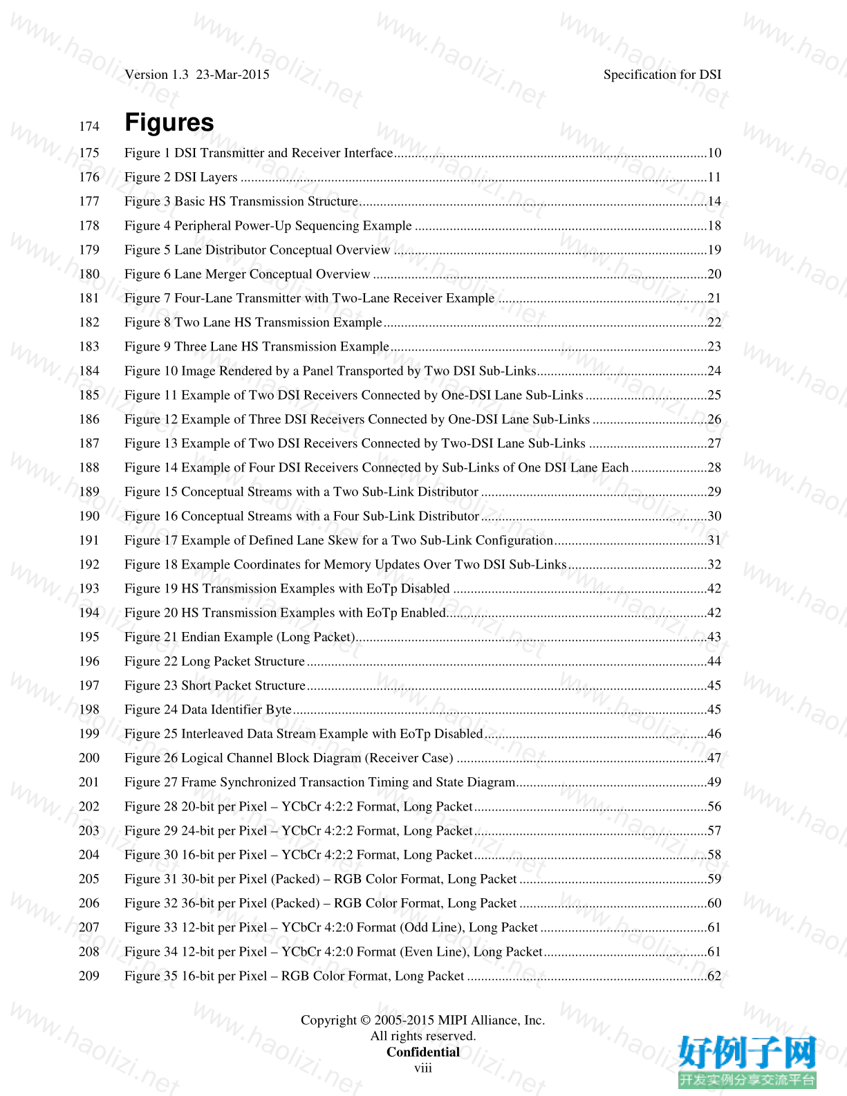
174 Figures
Figure 1 DSI Transmitter and Receiver Interface..........................................................................................10
175
Figure 2 DSI Layers ......................................................................................................................................11
176
Figure 3 Basic HS Transmission Structure....................................................................................................14
177
Figure 4 Peripheral Power-Up Sequencing Example ....................................................................................18
178
Figure 5 Lane Distributor Conceptual Overview ..........................................................................................19
179
Figure 6 Lane Merger Conceptual Overview ................................................................................................20
180
Figure 7 Four-Lane Transmitter with Two-Lane Receiver Example ............................................................21
181
Figure 8 Two Lane HS Transmission Example.............................................................................................22
182
Figure 9 Three Lane HS Transmission Example...........................................................................................23
183
Figure 10 Image Rendered by a Panel Transported by Two DSI Sub-Links.................................................24
184
Figure 11 Example of Two DSI Receivers Connected by One-DSI Lane Sub-Links...................................25
185
Figure 12 Example of Three DSI Receivers Connected by One-DSI Lane Sub-Links.................................26
186
Figure 13 Example of Two DSI Receivers Connected by Two-DSI Lane Sub-Links ..................................27
187
Figure 14 Example of Four DSI Receivers Connected by Sub-Links of One DSI Lane Each ......................28
188
Figure 15 Conceptual Streams with a Two Sub-Link Distributor .................................................................29
189
Figure 16 Conceptual Streams with a Four Sub-Link Distributor.................................................................30
190
Figure 17 Example of Defined Lane Skew for a Two Sub-Link Configuration............................................31
191
Figure 18 Example Coordinates for Memory Updates Over Two DSI Sub-Links........................................32
192
Figure 19 HS Transmission Examples with EoTp Disabled .........................................................................42
193
Figure 20 HS Transmission Examples with EoTp Enabled...........................................................................42
194
Figure 21 Endian Example (Long Packet).....................................................................................................43
195
Figure 22 Long Packet Structure ...................................................................................................................44
196
Figure 23 Short Packet Structure...................................................................................................................45
197
Figure 24 Data Identifier Byte.......................................................................................................................45
198
Figure 25 Interleaved Data Stream Example with EoTp Disabled................................................................46
199
Figure 26 Logical Channel Block Diagram (Receiver Case) ........................................................................47
200
Figure 27 Frame Synchronized Transaction Timing and State Diagram.......................................................49
201
Figure 28 20-bit per Pixel – YCbCr 4:2:2 Format, Long Packet...................................................................56
202
Figure 29 24-bit per Pixel – YCbCr 4:2:2 Format, Long Packet...................................................................57
203
Figure 30 16-bit per Pixel – YCbCr 4:2:2 Format, Long Packet...................................................................58
204
Figure 31 30-bit per Pixel (Packed) – RGB Color Format, Long Packet ......................................................59
205
Figure 32 36-bit per Pixel (Packed) – RGB Color Format, Long Packet ......................................................60
206
Figure 33 12-bit per Pixel – YCbCr 4:2:0 Format (Odd Line), Long Packet ................................................61
207
Figure 34 12-bit per Pixel – YCbCr 4:2:0 Format (Even Line), Long Packet...............................................61
208
Figure 35 16-bit per Pixel – RGB Color Format, Long Packet .....................................................................62
209
Copyright © 2005-2015 MIPI Alliance, Inc.
All rights reserved.
Confidential
viiiVersion 1.3 23-Mar-2015
Specification for DSI
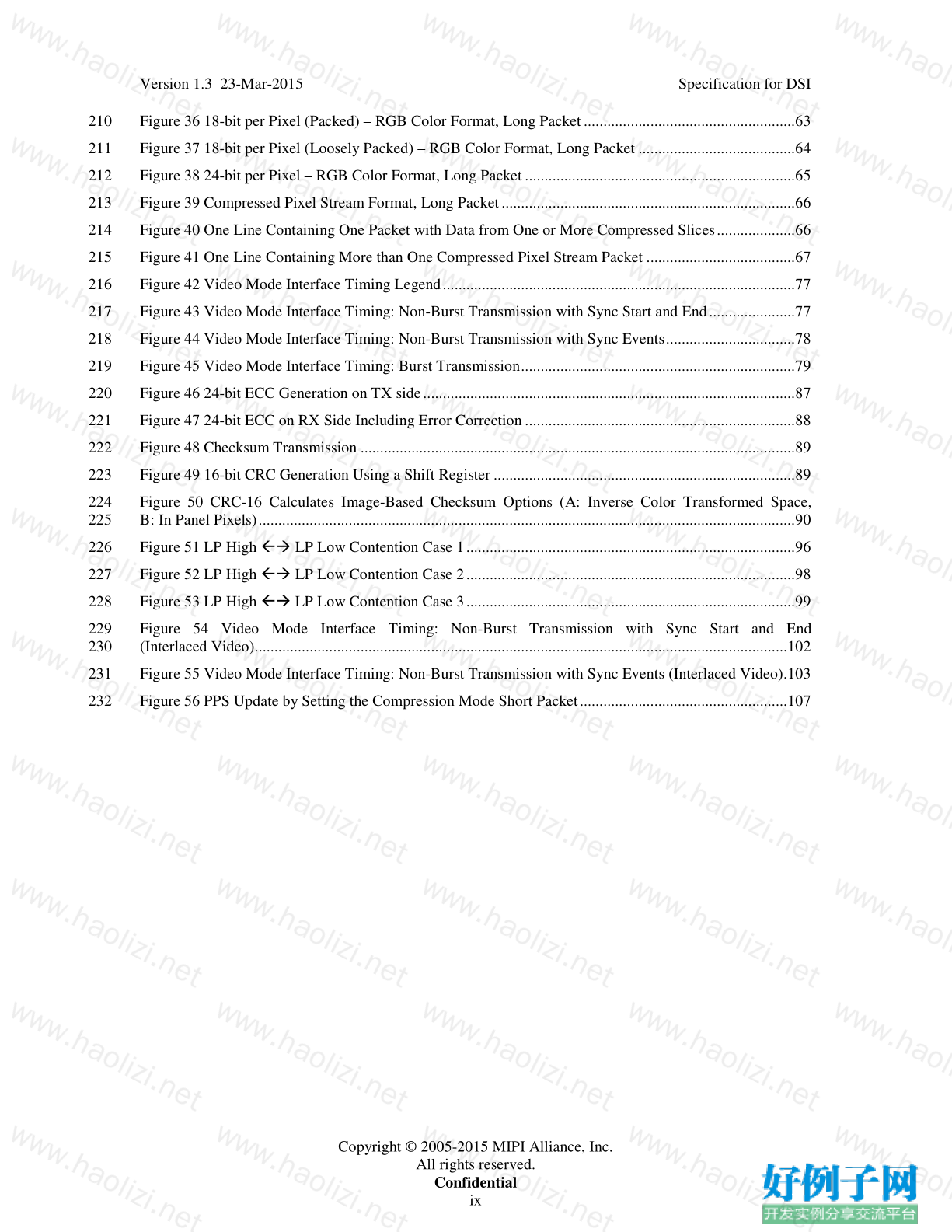
Figure 36 18-bit per Pixel (Packed) – RGB Color Format, Long Packet ......................................................63
210
Figure 37 18-bit per Pixel (Loosely Packed) – RGB Color Format, Long Packet ........................................64
211
Figure 38 24-bit per Pixel – RGB Color Format, Long Packet .....................................................................65
212
Figure 39 Compressed Pixel Stream Format, Long Packet ...........................................................................66
213
Figure 40 One Line Containing One Packet with Data from One or More Compressed Slices....................66
214
Figure 41 One Line Containing More than One Compressed Pixel Stream Packet ......................................67
215
Figure 42 Video Mode Interface Timing Legend..........................................................................................77
216
Figure 43 Video Mode Interface Timing: Non-Burst Transmission with Sync Start and End ......................77
217
Figure 44 Video Mode Interface Timing: Non-Burst Transmission with Sync Events.................................78
218
Figure 45 Video Mode Interface Timing: Burst Transmission......................................................................79
219
Figure 46 24-bit ECC Generation on TX side ...............................................................................................87
220
Figure 47 24-bit ECC on RX Side Including Error Correction .....................................................................88
221
Figure 48 Checksum Transmission ...............................................................................................................89
222
Figure 49 16-bit CRC Generation Using a Shift Register .............................................................................89
223
Figure 50 CRC-16 Calculates Image-Based Checksum Options (A: Inverse Color Transformed Space,
224
B: In Panel Pixels).........................................................................................................................................90
225
Figure 51 LP High ß LP Low Contention Case 1 ....................................................................................96
226
Figure 52 LP High ß LP Low Contention Case 2 ....................................................................................98
227
Figure 53 LP High ß LP Low Contention Case 3 ....................................................................................99
228
Figure 54 Video Mode Interface Timing: Non-Burst Transmission with Sync Start and End
229
(Interlaced Video)........................................................................................................................................102
230
Figure 55 Video Mode Interface Timing: Non-Burst Transmission with Sync Events (Interlaced Video).103
231
Figure 56 PPS Update by Setting the Compression Mode Short Packet.....................................................107
232
Copyright © 2005-2015 MIPI Alliance, Inc.
All rights reserved.
Confidential
ixVersion 1.3 23-Mar-2015
Specification for DSI
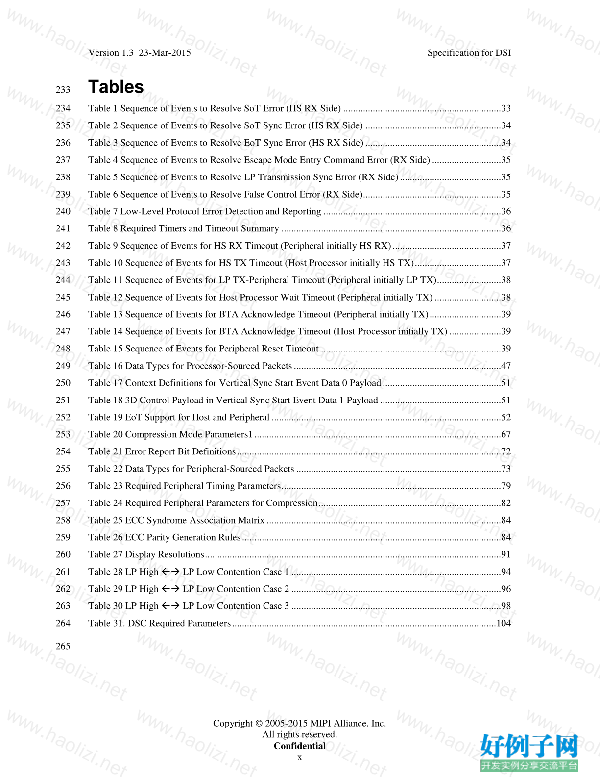
233 Tables
Table 1 Sequence of Events to Resolve SoT Error (HS RX Side) ................................................................33
234
Table 2 Sequence of Events to Resolve SoT Sync Error (HS RX Side) .......................................................34
235
Table 3 Sequence of Events to Resolve EoT Sync Error (HS RX Side) .......................................................34
236
Table 4 Sequence of Events to Resolve Escape Mode Entry Command Error (RX Side) ............................35
237
Table 5 Sequence of Events to Resolve LP Transmission Sync Error (RX Side).........................................35
238
Table 6 Sequence of Events to Resolve False Control Error (RX Side)........................................................35
239
Table 7 Low-Level Protocol Error Detection and Reporting ........................................................................36
240
Table 8 Required Timers and Timeout Summary .........................................................................................36
241
Table 9 Sequence of Events for HS RX Timeout (Peripheral initially HS RX)............................................37
242
Table 10 Sequence of Events for HS TX Timeout (Host Processor initially HS TX)...................................37
243
Table 11 Sequence of Events for LP TX-Peripheral Timeout (Peripheral initially LP TX)..........................38
244
Table 12 Sequence of Events for Host Processor Wait Timeout (Peripheral initially TX) ...........................38
245
Table 13 Sequence of Events for BTA Acknowledge Timeout (Peripheral initially TX).............................39
246
Table 14 Sequence of Events for BTA Acknowledge Timeout (Host Processor initially TX) .....................39
247
Table 15 Sequence of Events for Peripheral Reset Timeout .........................................................................39
248
Table 16 Data Types for Processor-Sourced Packets....................................................................................47
249
Table 17 Context Definitions for Vertical Sync Start Event Data 0 Payload ................................................51
250
Table 18 3D Control Payload in Vertical Sync Start Event Data 1 Payload .................................................51
251
Table 19 EoT Support for Host and Peripheral .............................................................................................52
252
Table 20 Compression Mode Parameters1 ....................................................................................................67
253
Table 21 Error Report Bit Definitions...........................................................................................................72
254
Table 22 Data Types for Peripheral-Sourced Packets ...................................................................................73
255
Table 23 Required Peripheral Timing Parameters.........................................................................................79
256
Table 24 Required Peripheral Parameters for Compression..........................................................................82
257
Table 25 ECC Syndrome Association Matrix ...............................................................................................84
258
Table 26 ECC Parity Generation Rules.........................................................................................................84
259
Table 27 Display Resolutions........................................................................................................................91
260
Table 28 LP High ß LP Low Contention Case 1 .....................................................................................94
261
Table 29 LP High ß LP Low Contention Case 2 .....................................................................................96
262
Table 30 LP High ß LP Low Contention Case 3 .....................................................................................98
263
Table 31. DSC Required Parameters...........................................................................................................104
264
265
好例子网口号:伸出你的我的手 — 分享!
小贴士
感谢您为本站写下的评论,您的评论对其它用户来说具有重要的参考价值,所以请认真填写。
- 类似“顶”、“沙发”之类没有营养的文字,对勤劳贡献的楼主来说是令人沮丧的反馈信息。
- 相信您也不想看到一排文字/表情墙,所以请不要反馈意义不大的重复字符,也请尽量不要纯表情的回复。
- 提问之前请再仔细看一遍楼主的说明,或许是您遗漏了。
- 请勿到处挖坑绊人、招贴广告。既占空间让人厌烦,又没人会搭理,于人于己都无利。
关于好例子网
本站旨在为广大IT学习爱好者提供一个非营利性互相学习交流分享平台。本站所有资源都可以被免费获取学习研究。本站资源来自网友分享,对搜索内容的合法性不具有预见性、识别性、控制性,仅供学习研究,请务必在下载后24小时内给予删除,不得用于其他任何用途,否则后果自负。基于互联网的特殊性,平台无法对用户传输的作品、信息、内容的权属或合法性、安全性、合规性、真实性、科学性、完整权、有效性等进行实质审查;无论平台是否已进行审查,用户均应自行承担因其传输的作品、信息、内容而可能或已经产生的侵权或权属纠纷等法律责任。本站所有资源不代表本站的观点或立场,基于网友分享,根据中国法律《信息网络传播权保护条例》第二十二与二十三条之规定,若资源存在侵权或相关问题请联系本站客服人员,点此联系我们。关于更多版权及免责申明参见 版权及免责申明


网友评论
我要评论