

实例介绍
【实例简介】MIPI-DPHY-Specification
【实例截图】

【核心代码】
Contents
Draft Version 1.00.00 – 14 May 2009.............................................................................................................. i
43
1
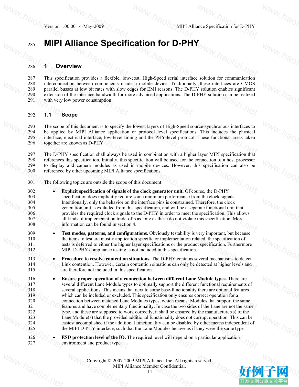
Overview ............................................................................................................................................... 14
44
1.1
Scope ............................................................................................................................................. 14
45
1.2
Purpose .......................................................................................................................................... 15
46
2
Terminology .......................................................................................................................................... 16
47
2.1
Definitions ..................................................................................................................................... 16
48
2.2
Abbreviations ................................................................................................................................ 17
49
2.3
Acronyms ...................................................................................................................................... 17
50
3
D-PHY Introduction .............................................................................................................................. 20
51
3.1
Summary of PHY Functionality .................................................................................................... 20
52
3.2
Mandatory Functionality ............................................................................................................... 20
53
4
Architecture ........................................................................................................................................... 21
54
4.1
Lane Modules ................................................................................................................................ 21
55
4.2
Master and Slave ........................................................................................................................... 22
56
4.3
High Frequency Clock Generation ................................................................................................ 22
57
4.4
Clock Lane, Data Lanes and the PHY-Protocol Interface ............................................................. 22
58
4.5
Selectable Lane Options ................................................................................................................ 23
59
4.6
Lane Module Types ....................................................................................................................... 25
60
4.6.1
Unidirectional Data Lane ....................................................................................................... 26
61
4.6.2
Bi-directional Data Lanes ...................................................................................................... 26
62
4.6.3
Clock Lane ............................................................................................................................. 27
63
4.7
Configurations ............................................................................................................................... 27
64
4.7.1
Unidirectional Configurations ............................................................................................... 29
65
4.7.2
Bi-Directional Half-Duplex Configurations .......................................................................... 31
66
4.7.3
Mixed Data Lane Configurations .......................................................................................... 32
67
5
Global Operation ................................................................................................................................... 33
68 Version 1.00.00 14-May-2009
MIPI Alliance Specification for D-PHY
Copyright © 2007-2009 MIPI Alliance, Inc. All rights reserved.
MIPI Alliance Member Confidential.
iv
5.1
Transmission Data Structure ......................................................................................................... 33
69
5.1.1
Data Units .............................................................................................................................. 33
70
5.1.2
Bit order, Serialization, and De-Serialization ........................................................................ 33
71
5.1.3
Encoding and Decoding ........................................................................................................ 33
72
5.1.4
Data Buffering ....................................................................................................................... 33
73
5.2
Lane States and Line Levels .......................................................................................................... 33
74
5.3
Operating Modes: Control, High-Speed, and Escape .................................................................... 34
75
5.4
High-Speed Data Transmission ..................................................................................................... 35
76
5.4.1
Burst Payload Data ................................................................................................................ 35
77
5.4.2
Start-of-Transmission ............................................................................................................ 35
78
5.4.3
End-of-Transmission ............................................................................................................. 36
79
5.4.4
HS Data Transmission Burst ................................................................................................. 36
80
5.5
Bi-directional Data Lane Turnaround ............................................................................................ 38
81
5.6
Escape Mode ................................................................................................................................. 41
82
5.6.1
Remote Triggers .................................................................................................................... 42
83
5.6.2
Low-Power Data Transmission ............................................................................................. 43
84
5.6.3
Ultra-Low Power State .......................................................................................................... 43
85
5.6.4
Escape Mode State Machine .................................................................................................. 43
86
5.7
High-Speed Clock Transmission ................................................................................................... 45
87
5.8
Clock Lane Ultra-Low Power State ............................................................................................... 50
88
5.9
Global Operation Timing Parameters ............................................................................................52
89
5.10 System Power States ...................................................................................................................... 56
90
5.11 Initialization ................................................................................................................................... 56
91
5.12 Calibration ..................................................................................................................................... 56
92
5.13 Global Operation Flow Diagram ................................................................................................... 57
93
5.14 Data Rate Dependent Parameters (informative) ............................................................................ 58
94
5.14.1
Parameters Containing Only UI Values ................................................................................ 59
95
5.14.2
Parameters Containing Time and UI values .......................................................................... 59
96 Version 1.00.00 14-May-2009
MIPI Alliance Specification for D-PHY
Copyright © 2007-2009 MIPI Alliance, Inc. All rights reserved.
MIPI Alliance Member Confidential.
v
5.14.3
Parameters Containing Only Time Values ............................................................................ 59
97
5.14.4
Parameters Containing Only Time Values That Are Not Data Rate Dependent ................... 60
98
6
Fault Detection ...................................................................................................................................... 61
99
6.1
Contention Detection ..................................................................................................................... 61
100
6.2
Sequence Error Detection .............................................................................................................. 61
101
6.2.1
SoT Error ............................................................................................................................... 62
102
6.2.2
SoT Sync Error ...................................................................................................................... 62
103
6.2.3
EoT Sync Error ...................................................................................................................... 62
104
6.2.4
Escape Mode Entry Command Error ..................................................................................... 62
105
6.2.5
LP Transmission Sync Error .................................................................................................. 62
106
6.2.6
False Control Error ................................................................................................................ 62
107
6.3
Protocol Watchdog Timers (informative) ...................................................................................... 62
108
6.3.1
HS RX Timeout ..................................................................................................................... 62
109
6.3.2
HS TX Timeout ..................................................................................................................... 62
110
6.3.3
Escape Mode Timeout ...........................................................................................................62
111
6.3.4
Escape Mode Silence Timeout .............................................................................................. 63
112
6.3.5
Turnaround Errors ................................................................................................................. 63
113
7
Interconnect and Lane Configuration .................................................................................................... 64
114
7.1
Lane Configuration ........................................................................................................................ 64
115
7.2
Boundary Conditions ..................................................................................................................... 64
116
7.3
Definitions ..................................................................................................................................... 64
117
7.4
S-parameter Specifications ............................................................................................................ 65
118
7.5
Characterization Conditions .......................................................................................................... 65
119
7.6
Interconnect Specifications ........................................................................................................... 66
120
7.6.1
Differential Characteristics .................................................................................................... 66
121
7.6.2
Common-mode Characteristics.............................................................................................. 67
122
7.6.3
Intra-Lane Cross-Coupling .................................................................................................... 67
123
7.6.4
Mode-Conversion Limits ....................................................................................................... 67
124 Version 1.00.00 14-May-2009
MIPI Alliance Specification for D-PHY
Copyright © 2007-2009 MIPI Alliance, Inc. All rights reserved.
MIPI Alliance Member Confidential.
vi
7.6.5
Inter-Lane Cross-Coupling .................................................................................................... 67
125
7.6.6
Inter-Lane Static Skew .......................................................................................................... 68
126
7.7
Driver and Receiver Characteristics .............................................................................................. 68
127
7.7.1
Differential Characteristics .................................................................................................... 68
128
7.7.2
Common-Mode Characteristics ............................................................................................. 69
129
7.7.3
Mode-Conversion Limits ....................................................................................................... 69
130
7.7.4
Inter-Lane Matching .............................................................................................................. 69
131
8
Electrical Characteristics ....................................................................................................................... 70
132
8.1
Driver Characteristics .................................................................................................................... 71
133
8.1.1
High-Speed Transmitter ........................................................................................................71
134
8.1.2
Low-Power Transmitter .........................................................................................................75
135
8.2
Receiver Characteristics ................................................................................................................ 80
136
8.2.1
High-Speed Receiver ............................................................................................................. 80
137
8.2.2
Low-Power Receiver ............................................................................................................. 82
138
8.3
Line Contention Detection ............................................................................................................ 83
139
8.4
Input Characteristics ...................................................................................................................... 84
140
9
High-Speed Data-Clock Timing ............................................................................................................ 86
141
9.1
High-Speed Clock Timing ............................................................................................................. 86
142
9.2
Forward High-Speed Data Transmission Timing .......................................................................... 87
143
9.2.1
Data-Clock Timing Specifications ........................................................................................ 88
144
9.3
Reverse High-Speed Data Transmission Timing .......................................................................... 89
145
10
Regulatory Requirements .................................................................................................................. 91
146
Annex A Logical PHY-Protocol Interface Description (informative) .......................................................... 92
147
A.1
Signal Description ......................................................................................................................... 92
148
A.2
High-Speed Transmit from the Master Side ................................................................................ 100
149
A.3
High-Speed Receive at the Slave Side ........................................................................................ 100
150
A.4
High-Speed Transmit from the Slave Side .................................................................................. 101
151
A.5
High-Speed Receive at the Master Side ...................................................................................... 101
152 Version 1.00.00 14-May-2009
MIPI Alliance Specification for D-PHY
Copyright © 2007-2009 MIPI Alliance, Inc. All rights reserved.
MIPI Alliance Member Confidential.
vii
A.6
Low-Power Data Transmission ...................................................................................................102
153
A.7
Low-Power Data Reception ........................................................................................................ 103
154
A.8
Turn-around ................................................................................................................................. 103
155
Annex B Interconnect Design Guidelines (informative) ............................................................................. 105
156
B.1
Practical Distances ....................................................................................................................... 105
157
B.2
RF Frequency Bands: Interference ..............................................................................................105
158
B.3
Transmission Line Design ........................................................................................................... 105
159
B.4
Reference Layer ........................................................................................................................... 106
160
B.5
Printed-Circuit Board .................................................................................................................. 106
161
B.6
Flex-foils ..................................................................................................................................... 106
162
B.7
Series Resistance ......................................................................................................................... 106
163
B.8
Connectors ................................................................................................................................... 106
164
Annex C 8b9b Line Coding for D-PHY (normative) .................................................................................. 107
165
C.1
Line Coding Features .................................................................................................................. 108
166
C.1.1
Enabled Features for the Protocol ....................................................................................... 108
167
C.1.2
Enabled Features for the PHY ............................................................................................. 108
168
C.2
Coding Scheme ............................................................................................................................ 108
169
C.2.1
8b9b Coding Properties ....................................................................................................... 108
170
C.2.2
Data Codes: Basic Code Set ................................................................................................ 109
171
C.2.3
Comma Codes: Unique Exception Codes ............................................................................ 110
172
C.2.4
Control Codes: Regular Exception Codes ........................................................................... 110
173
C.2.5
Complete Coding Scheme ................................................................................................... 111
174
C.3
Operation with the D-PHY .......................................................................................................... 111
175
C.3.1
Payload: Data and Control ................................................................................................... 111
176
C.3.2
Details for HS Transmission ................................................................................................ 112
177
C.3.3
Details for LP Transmission ................................................................................................ 112
178
C.4
Error Signaling ............................................................................................................................ 113
179
C.5
Extended PPI ............................................................................................................................... 113
180 Version 1.00.00 14-May-2009
MIPI Alliance Specification for D-PHY
Copyright © 2007-2009 MIPI Alliance, Inc. All rights reserved.
MIPI Alliance Member Confidential.
viii
C.6
Complete Code Set ...................................................................................................................... 115
181
182 Version 1.00.00 14-May-2009
MIPI Alliance Specification for D-PHY
Copyright © 2007-2009 MIPI Alliance, Inc. All rights reserved.
MIPI Alliance Member Confidential.
9
183 Figures
Figure 1 Universal Lane Module Functions ................................................................................................. 21
184
Figure 2 Two Data Lane PHY Configuration .............................................................................................. 23
185
Figure 3 Option Selection Flow Graph ........................................................................................................ 24
186
Figure 4 Universal Lane Module Architecture ............................................................................................. 25
187
Figure 5 Lane Symbol Macros and Symbols Legend ................................................................................... 28
188
Figure 6 All Possible Data Lane Types and a Basic Unidirectional Clock Lane ......................................... 29
189
Figure 7 Unidirectional Single Data Lane Configuration ............................................................................ 30
190
Figure 8 Unidirectional Multiple Data Lane Configuration without LPDT ................................................. 30
191
Figure 9 Two Directions Using Two Independent Unidirectional PHYs without LPDT ............................ 31
192
Figure 10 Bidirectional Single Data Lane Configuration ............................................................................. 31
193
Figure 11 Bi-directional Multiple Data Lane Configuration ........................................................................ 32
194
Figure 12 Mixed Type Multiple Data Lane Configuration .......................................................................... 32
195
Figure 13 Line Levels................................................................................................................................... 34
196
Figure 14 High-Speed Data Transmission in Bursts .................................................................................... 36
197
Figure 15 TX and RX State Machines for High-Speed Data Transmission ................................................. 37
198
Figure 16 Turnaround Procedure ................................................................................................................. 39
199
Figure 17 Turnaround State Machine ........................................................................................................... 40
200
Figure 18 Trigger-Reset Command in Escape Mode ................................................................................... 42
201
Figure 19 Two Data Byte Low-Power Data Transmission Example ........................................................... 43
202
Figure 20 Escape Mode State Machine ........................................................................................................ 44
203
Figure 21 Switching the Clock Lane between Clock Transmission and Low-Power Mode ........................ 47
204
Figure 22 High-Speed Clock Transmission State Machine .......................................................................... 49
205
Figure 23 Clock Lane Ultra-Low Power State State Machine ..................................................................... 51
206
Figure 24 Data Lane Module State Diagram ................................................................................................ 57
207
Figure 25 Clock Lane Module State Diagram .............................................................................................. 58
208
Figure 26 Point-to-point Interconnect .......................................................................................................... 64
209 Version 1.00.00 14-May-2009
MIPI Alliance Specification for D-PHY
Copyright © 2007-2009 MIPI Alliance, Inc. All rights reserved.
MIPI Alliance Member Confidential.
10
Figure 27 Set-up for S-parameter Characterization of RX, TX and TLIS ................................................... 65
210
Figure 28 Template for Differential Insertion Losses .................................................................................. 66
211
Figure 29 Template for Differential Reflection at Both Ports ...................................................................... 66
212
Figure 30 Inter-Lane Common-mode Cross-Coupling Template................................................................. 67
213
Figure 31 Inter-Lane Differential Cross-Coupling Template ....................................................................... 68
214
Figure 32 Differential Reflection Template for Lane Module Receivers ..................................................... 68
215
Figure 33 Differential Reflection Template for Lane Module Transmitters ................................................ 69
216
Figure 34 Template for RX Common-Mode Return Loss ............................................................................ 69
217
Figure 35 Electrical Functions of a Fully Featured D-PHY Transceiver ..................................................... 70
218
Figure 36 D-PHY Signaling Levels ............................................................................................................. 71
219
Figure 37 Example HS Transmitter .............................................................................................................. 72
220
Figure 38 Ideal Single-ended and Resulting Differential HS Signals .......................................................... 73
221
Figure 39 Possible ΔVCMTX and ΔVOD Distortions of the Single-ended HS Signals .................................... 74
222
Figure 40 Example Circuit for VCMTX and VOD Measurements .................................................................... 74
223
Figure 41 Example LP Transmitter .............................................................................................................. 76
224
Figure 42 V-I Characteristic for LP Transmitter Driving Logic High ......................................................... 76
225
Figure 43 V-I Characteristic for LP Transmitter Driving Logic Low .......................................................... 77
226
Figure 44 LP Transmitter V-I Characteristic Measurement Setup ............................................................... 77
227
Figure 45 Slew Rate vs. CLOAD (Falling Edge) ............................................................................................. 79
228
Figure 46 Slew Rate vs. CLOAD (Rising Edge) .............................................................................................. 80
229
Figure 47 HS Receiver Implementation Example ........................................................................................ 80
230
Figure 48 Input Glitch Rejection of Low-Power Receivers ......................................................................... 82
231
Figure 49 Signaling and Contention Voltage Levels ................................................................................... 84
232
Figure 50 Pin Leakage Measurement Example Circuit ................................................................................ 85
233
Figure 51 Conceptual D-PHY Data and Clock Timing Compliance Measurement Planes.......................... 86
234
Figure 52 DDR Clock Definition ................................................................................................................. 87
235
Figure 53 Data to Clock Timing Definitions ................................................................................................ 88
236
Figure 54 Conceptual View of HS Data Transmission in Reverse Direction .............................................. 89
237 Version 1.00.00 14-May-2009
MIPI Alliance Specification for D-PHY
Copyright © 2007-2009 MIPI Alliance, Inc. All rights reserved.
MIPI Alliance Member Confidential.
11
Figure 55 Reverse High-Speed Data Transmission Timing at Slave Side ................................................... 90
238
Figure 56 Example High-Speed Transmission from the Master Side ........................................................ 100
239
Figure 57 Example High-Speed Receive at the Slave Side ........................................................................ 101
240
Figure 58 Example High-Speed Transmit from the Slave Side ................................................................. 101
241
Figure 59 Example High-Speed Receive at the Master Side ...................................................................... 102
242
Figure 60 Low-Power Data Transmission .................................................................................................. 102
243
Figure 61 Example Low-Power Data Reception ........................................................................................ 103
244
Figure 62 Example Turn-around Actions Transmit-to-Receive and Back to Transmit .............................. 104
245
Figure 63 Line Coding Layer ..................................................................................................................... 107
246
247
248 Version 1.00.00 14-May-2009
MIPI Alliance Specification for D-PHY
Copyright © 2007-2009 MIPI Alliance, Inc. All rights reserved.
MIPI Alliance Member Confidential.
12
249 Tables
Table 1 Lane Type Descriptors .................................................................................................................... 26
250
Table 2 Lane State Descriptions ................................................................................................................... 34
251
Table 3 Start-of-Transmission Sequence ...................................................................................................... 35
252
Table 4 End-of-Transmission Sequence ....................................................................................................... 36
253
Table 5 High-Speed Data Transmission State Machine Description ........................................................... 37
254
Table 6 Link Turnaround Sequence ............................................................................................................. 38
255
Table 7 Turnaround State Machine Description .......................................................................................... 40
256
Table 8 Escape Entry Codes ......................................................................................................................... 42
257
Table 9 Escape Mode State Machine Description ........................................................................................ 44
258
Table 10 Procedure to Switch Clock Lane to Low-Power Mode ................................................................. 48
259
Table 11 Procedure to Initiate High-Speed Clock Transmission ................................................................. 48
260
Table 12 Description of High-Speed Clock Transmission State Machine ................................................... 49
261
Table 13 Clock Lane Ultra-Low Power State State Machine Description ................................................... 51
262
Table 14 Global Operation Timing Parameters ............................................................................................ 53
263
Table 15 Initialization States ........................................................................................................................ 56
264
Table 16 HS Transmitter DC Specifications ................................................................................................ 75
265
Table 17 HS Transmitter AC Specifications ................................................................................................ 75
266
Table 18 LP Transmitter DC Specifications ................................................................................................. 77
267
Table 19 LP Transmitter AC Specifications ................................................................................................. 78
268
Table 20 HS Receiver DC Specifications .................................................................................................... 81
269
Table 21 HS Receiver AC Specifications .................................................................................................... 81
270
Table 22 LP Receiver DC specifications ...................................................................................................... 82
271
Table 23 LP Receiver AC Specifications ..................................................................................................... 83
272
Table 24 Contention Detector (LP-CD) DC Specifications ......................................................................... 84
273
Table 25 Pin Characteristic Specifications ................................................................................................... 85
274
Table 26 Clock Signal Specification ............................................................................................................ 87
275 Version 1.00.00 14-May-2009
MIPI Alliance Specification for D-PHY
Copyright © 2007-2009 MIPI Alliance, Inc. All rights reserved.
MIPI Alliance Member Confidential.
13
Table 27 Data-Clock Timing Specifications ................................................................................................ 88
276
Table 28 PPI Signals .................................................................................................................................... 92
277
Table 29 Encoding Table for 8b9b Line Coding of Data Words ............................................................... 109
278
Table 30 Comma Codes ............................................................................................................................. 110
279
Table 31 Regular Exception Code Structure .............................................................................................. 111
280
Table 32 Additional Signals for (Functional) PPI ...................................................................................... 113
281
Table 33 Code Set (8b9b Line Coding) ...................................................................................................... 115
好例子网口号:伸出你的我的手 — 分享!
小贴士
感谢您为本站写下的评论,您的评论对其它用户来说具有重要的参考价值,所以请认真填写。
- 类似“顶”、“沙发”之类没有营养的文字,对勤劳贡献的楼主来说是令人沮丧的反馈信息。
- 相信您也不想看到一排文字/表情墙,所以请不要反馈意义不大的重复字符,也请尽量不要纯表情的回复。
- 提问之前请再仔细看一遍楼主的说明,或许是您遗漏了。
- 请勿到处挖坑绊人、招贴广告。既占空间让人厌烦,又没人会搭理,于人于己都无利。
关于好例子网
本站旨在为广大IT学习爱好者提供一个非营利性互相学习交流分享平台。本站所有资源都可以被免费获取学习研究。本站资源来自网友分享,对搜索内容的合法性不具有预见性、识别性、控制性,仅供学习研究,请务必在下载后24小时内给予删除,不得用于其他任何用途,否则后果自负。基于互联网的特殊性,平台无法对用户传输的作品、信息、内容的权属或合法性、安全性、合规性、真实性、科学性、完整权、有效性等进行实质审查;无论平台是否已进行审查,用户均应自行承担因其传输的作品、信息、内容而可能或已经产生的侵权或权属纠纷等法律责任。本站所有资源不代表本站的观点或立场,基于网友分享,根据中国法律《信息网络传播权保护条例》第二十二与二十三条之规定,若资源存在侵权或相关问题请联系本站客服人员,点此联系我们。关于更多版权及免责申明参见 版权及免责申明

网友评论
我要评论