实例介绍
【实例截图】



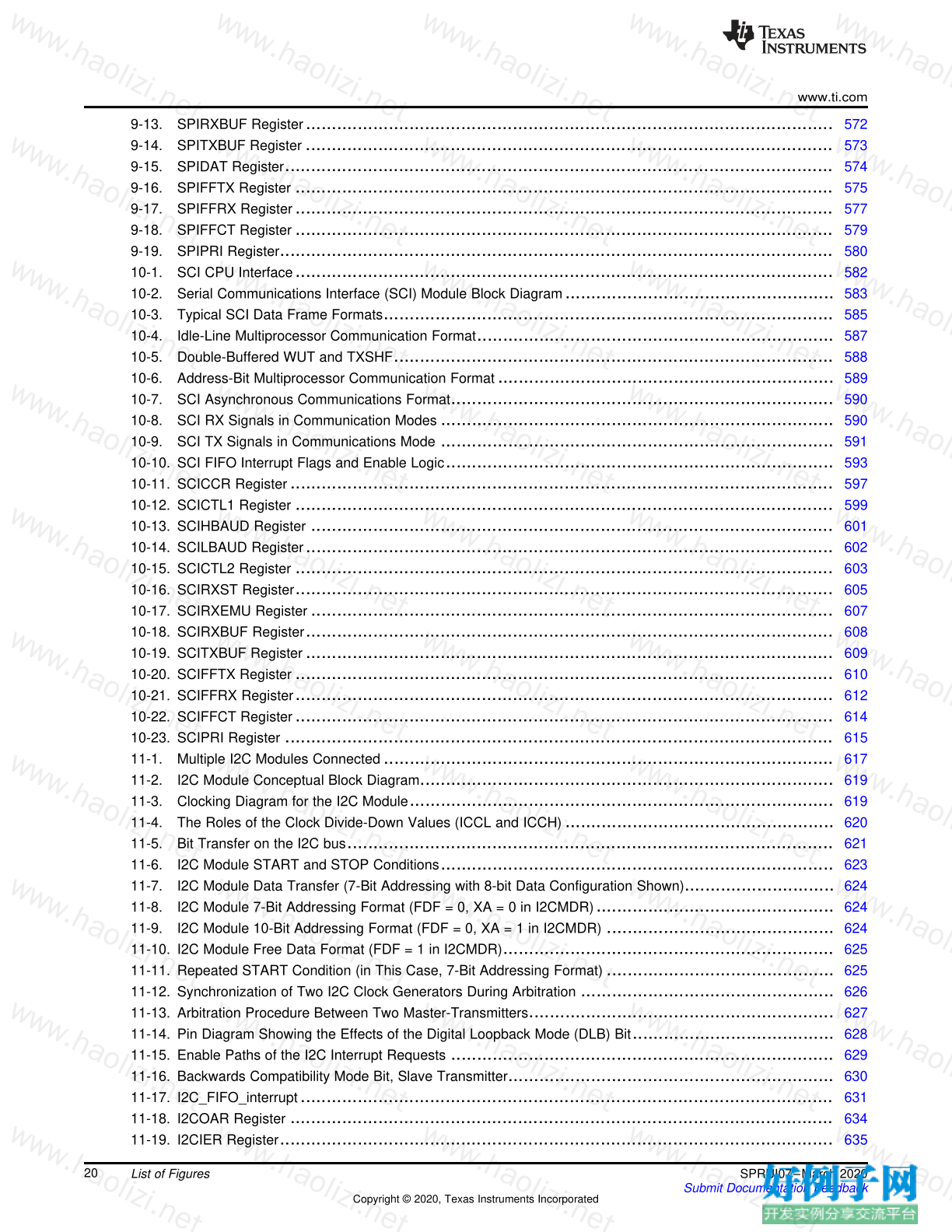
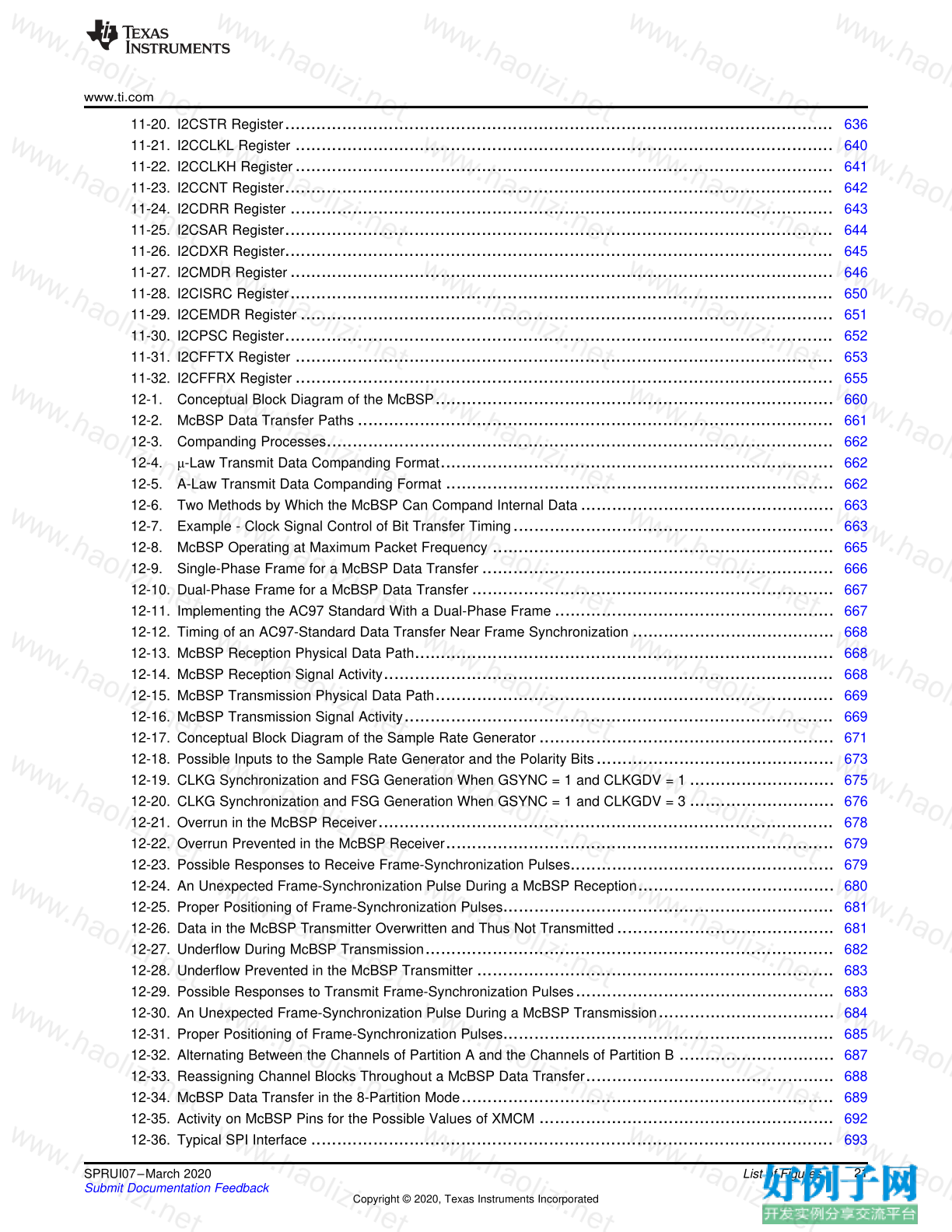
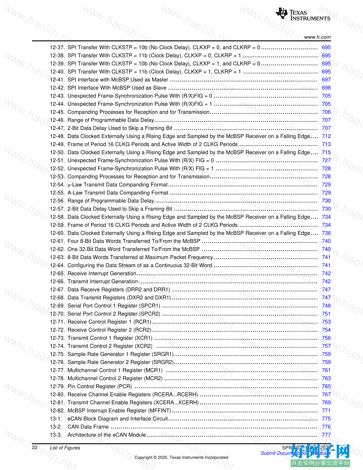
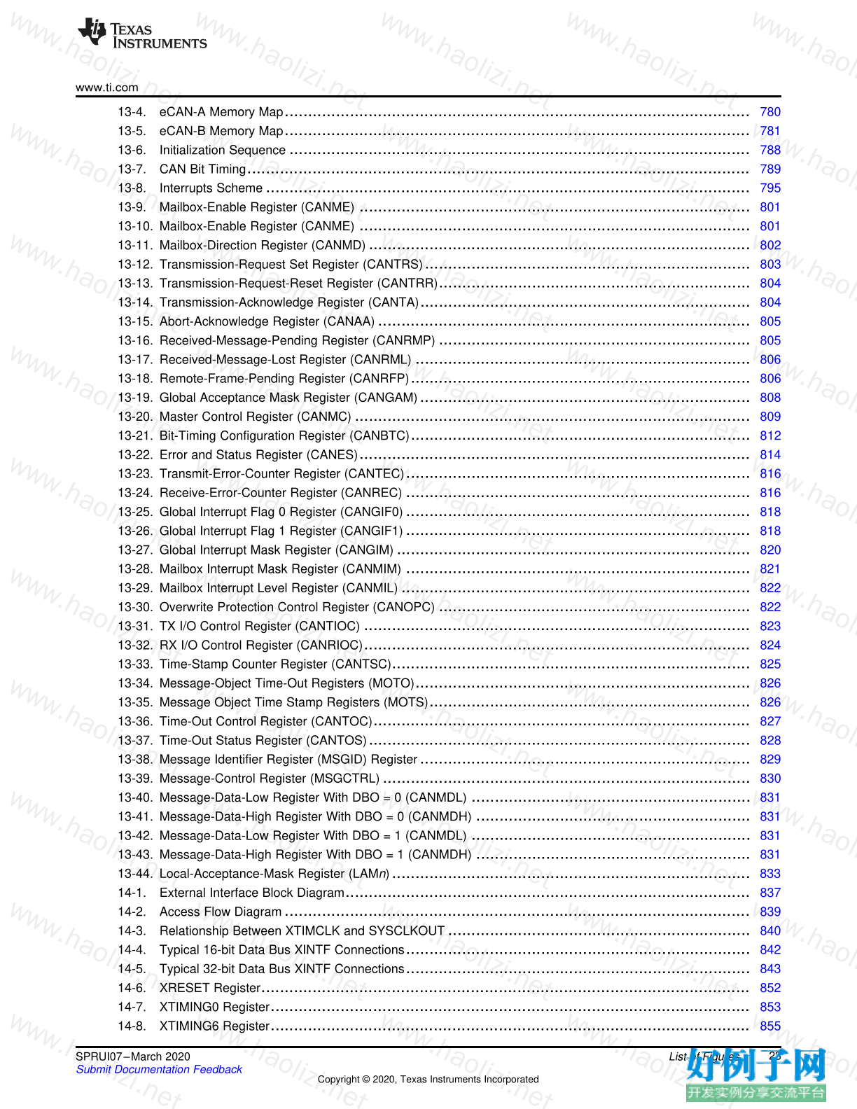
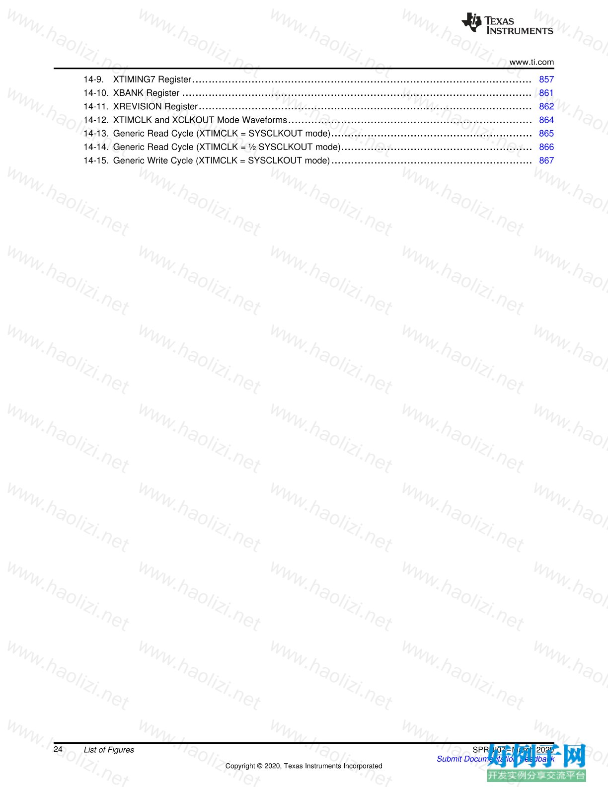
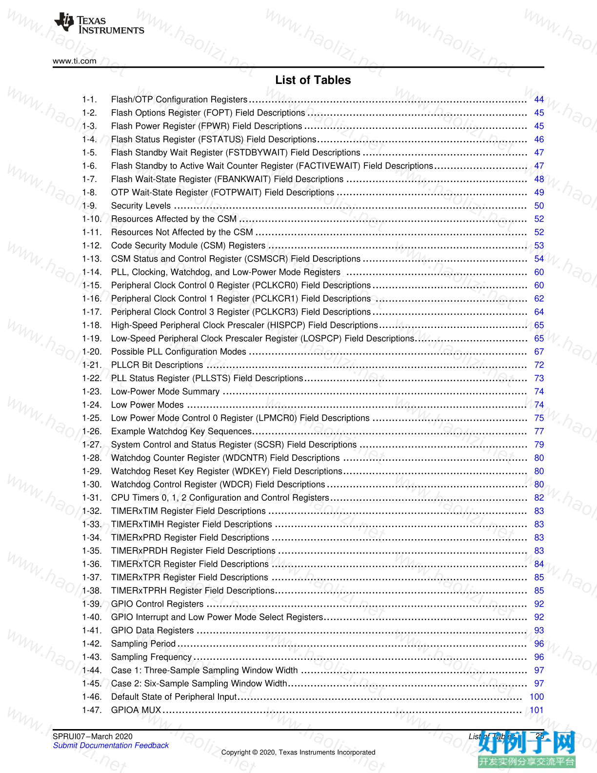


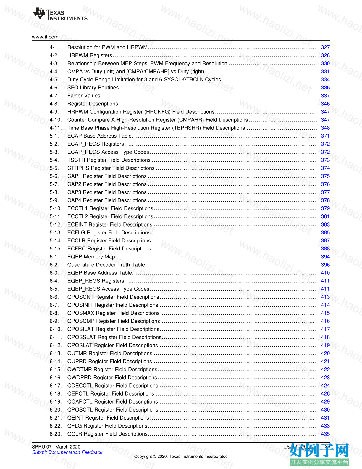
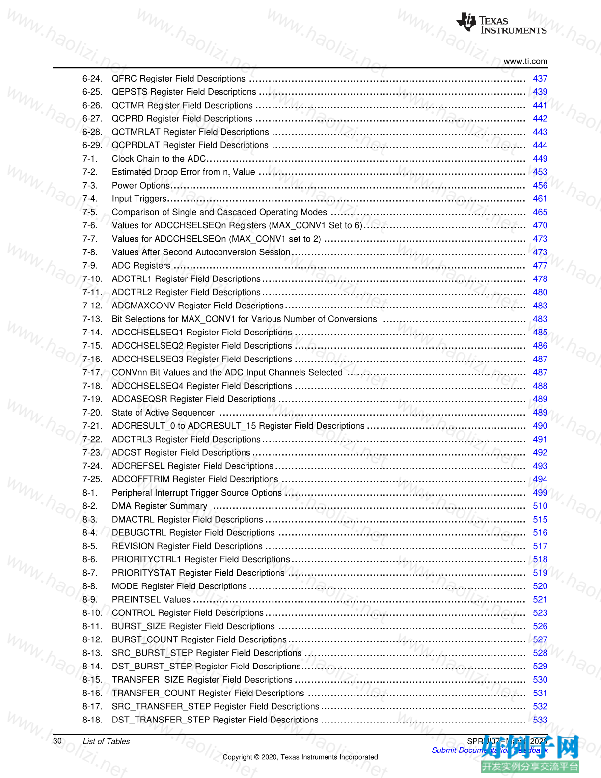
【核心代码】
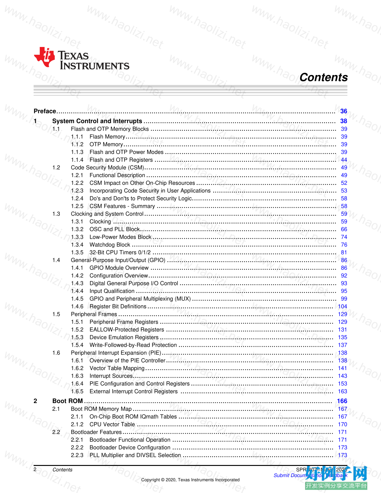
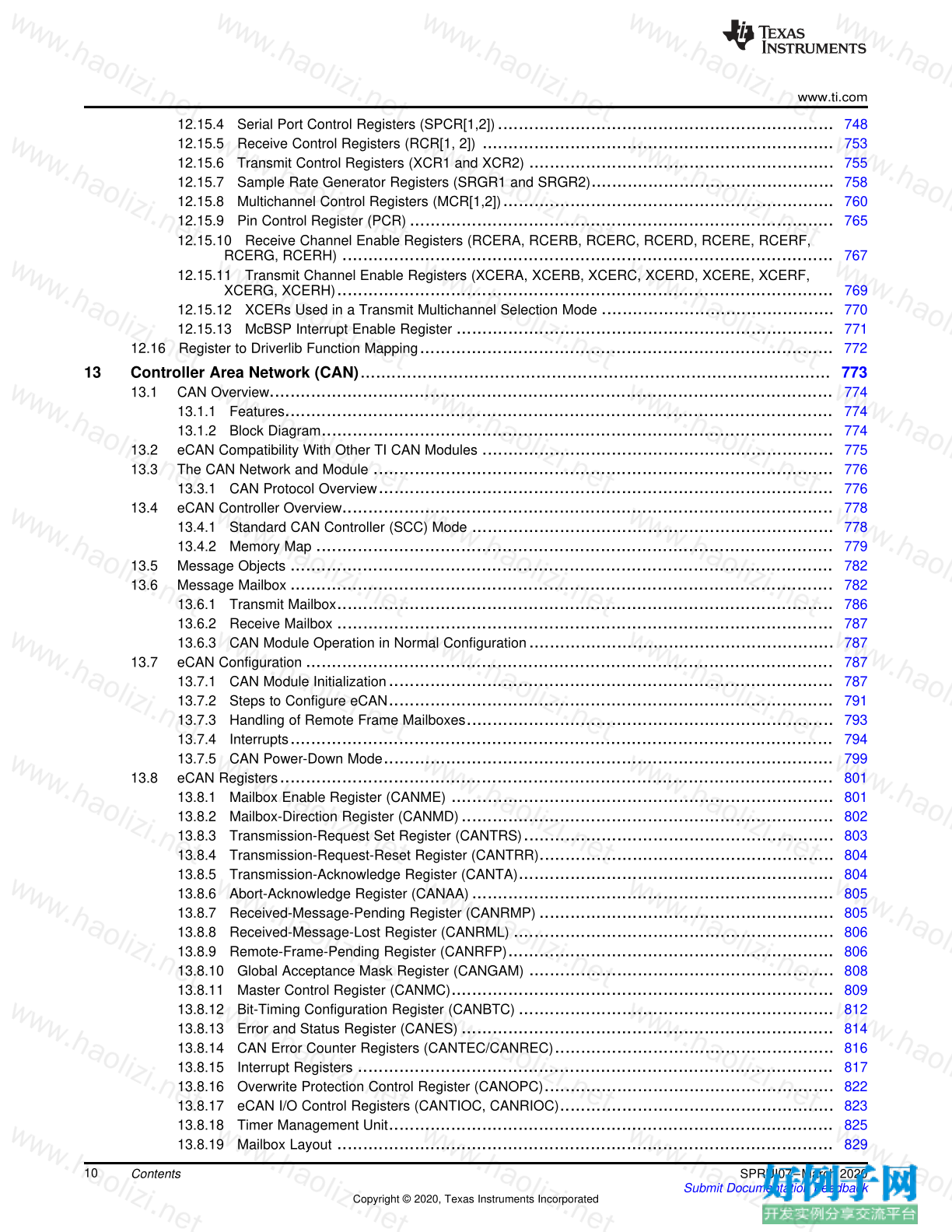
Contents
Preface ....................................................................................................................................... 36
1 System Control and Interrupts ............................................................................................. 38
1.1 Flash and OTP Memory Blocks .......................................................................................... 39
1.1.1 Flash Memory ...................................................................................................... 39
1.1.2 OTP Memory ....................................................................................................... 39
1.1.3 Flash and OTP Power Modes ................................................................................... 39
1.1.4 Flash and OTP Registers ........................................................................................ 44
1.2 Code Security Module (CSM) ............................................................................................. 49
1.2.1 Functional Description ............................................................................................ 49
1.2.2 CSM Impact on Other On-Chip Resources .................................................................... 52
1.2.3 Incorporating Code Security in User Applications ............................................................ 53
1.2.4 Do's and Don'ts to Protect Security Logic ...................................................................... 58
1.2.5 CSM Features - Summary ....................................................................................... 58
1.3 Clocking and System Control ............................................................................................. 59
1.3.1 Clocking ............................................................................................................ 59
1.3.2 OSC and PLL Block ............................................................................................... 66
1.3.3 Low-Power Modes Block ......................................................................................... 74
1.3.4 Watchdog Block ................................................................................................... 76
1.3.5 32-Bit CPU Timers 0/1/2 ......................................................................................... 81
1.4 General-Purpose Input/Output (GPIO) .................................................................................. 86
1.4.1 GPIO Module Overview .......................................................................................... 86
1.4.2 Configuration Overview ........................................................................................... 92
1.4.3 Digital General Purpose I/O Control ............................................................................ 93
1.4.4 Input Qualification ................................................................................................. 95
1.4.5 GPIO and Peripheral Multiplexing (MUX) ...................................................................... 99
1.4.6 Register Bit Definitions .......................................................................................... 104
1.5 Peripheral Frames ........................................................................................................ 129
1.5.1 Peripheral Frame Registers .................................................................................... 129
1.5.2 EALLOW-Protected Registers ................................................................................. 131
1.5.3 Device Emulation Registers .................................................................................... 135
1.5.4 Write-Followed-by-Read Protection ........................................................................... 137
1.6 Peripheral Interrupt Expansion (PIE) ................................................................................... 138
1.6.1 Overview of the PIE Controller ................................................................................. 138
1.6.2 Vector Table Mapping ........................................................................................... 141
1.6.3 Interrupt Sources ................................................................................................. 143
1.6.4 PIE Configuration and Control Registers ..................................................................... 153
1.6.5 External Interrupt Control Registers .......................................................................... 163
2 Boot ROM ........................................................................................................................ 166
2.1 Boot ROM Memory Map ................................................................................................. 167
2.1.1 On-Chip Boot ROM IQmath Tables ........................................................................... 167
2.1.2 CPU Vector Table ............................................................................................... 170
2.2 Bootloader Features ...................................................................................................... 171
2.2.1 Bootloader Functional Operation .............................................................................. 171
2.2.2 Bootloader Device Configuration .............................................................................. 173
2.2.3 PLL Multiplier and DIVSEL Selection ......................................................................... 173
www.ti.com
3 SPRUI07–March 2020
Submit Documentation Feedback
Copyright © 2020, Texas Instruments Incorporated
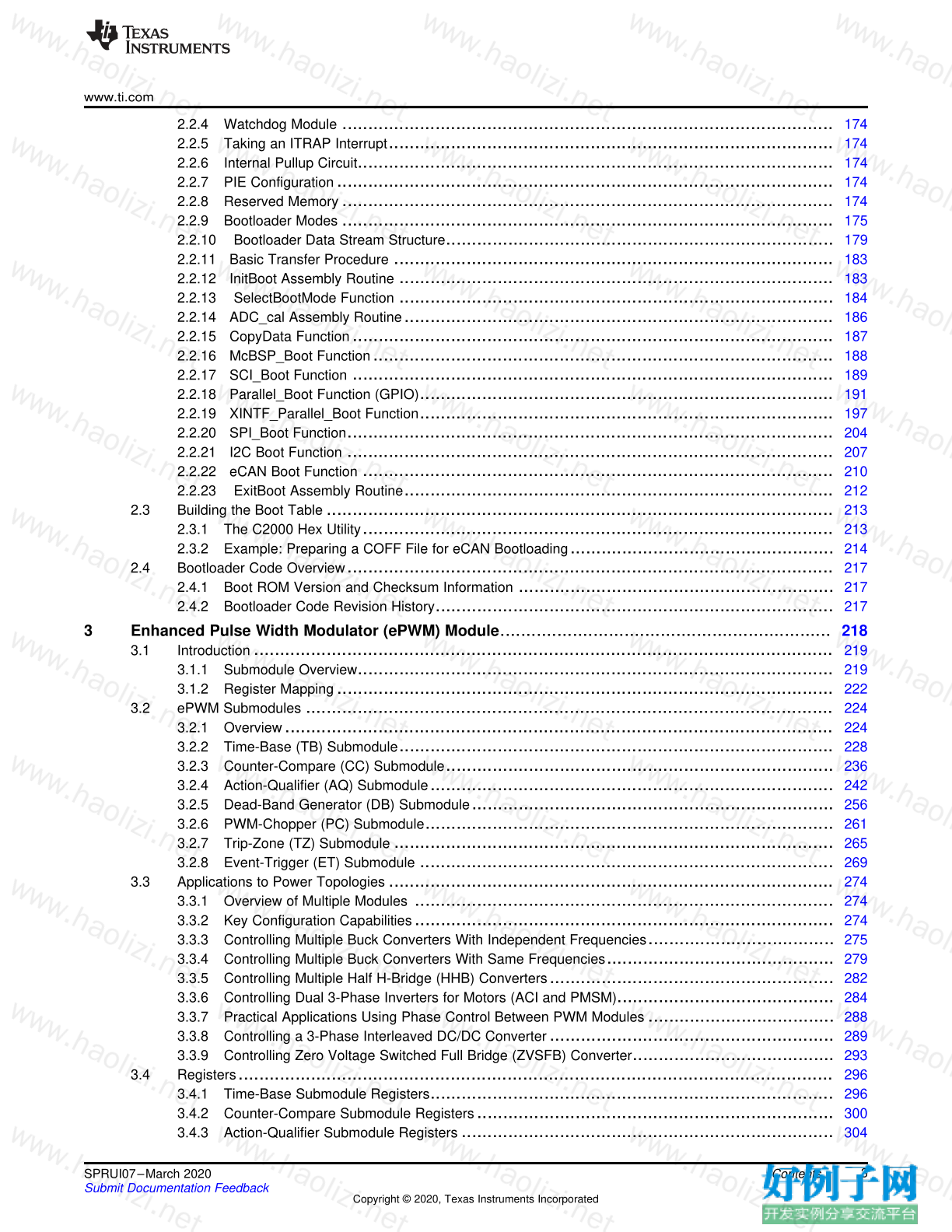
Contents
2.2.4 Watchdog Module ............................................................................................... 174
2.2.5 Taking an ITRAP Interrupt ...................................................................................... 174
2.2.6 Internal Pullup Circuit ............................................................................................ 174
2.2.7 PIE Configuration ................................................................................................ 174
2.2.8 Reserved Memory ............................................................................................... 174
2.2.9 Bootloader Modes ............................................................................................... 175
2.2.10 Bootloader Data Stream Structure ........................................................................... 179
2.2.11 Basic Transfer Procedure ..................................................................................... 183
2.2.12 InitBoot Assembly Routine .................................................................................... 183
2.2.13 SelectBootMode Function .................................................................................... 184
2.2.14 ADC_cal Assembly Routine ................................................................................... 186
2.2.15 CopyData Function ............................................................................................. 187
2.2.16 McBSP_Boot Function ......................................................................................... 188
2.2.17 SCI_Boot Function ............................................................................................. 189
2.2.18 Parallel_Boot Function (GPIO) ................................................................................ 191
2.2.19 XINTF_Parallel_Boot Function ................................................................................ 197
2.2.20 SPI_Boot Function .............................................................................................. 204
2.2.21 I2C Boot Function .............................................................................................. 207
2.2.22 eCAN Boot Function ........................................................................................... 210
2.2.23 ExitBoot Assembly Routine ................................................................................... 212
2.3 Building the Boot Table .................................................................................................. 213
2.3.1 The C2000 Hex Utility ........................................................................................... 213
2.3.2 Example: Preparing a COFF File for eCAN Bootloading ................................................... 214
2.4 Bootloader Code Overview .............................................................................................. 217
2.4.1 Boot ROM Version and Checksum Information ............................................................. 217
2.4.2 Bootloader Code Revision History ............................................................................. 217
3 Enhanced Pulse Width Modulator (ePWM) Module ................................................................ 218
3.1 Introduction ................................................................................................................ 219
3.1.1 Submodule Overview ............................................................................................ 219
3.1.2 Register Mapping ................................................................................................ 222
3.2 ePWM Submodules ...................................................................................................... 224
3.2.1 Overview .......................................................................................................... 224
3.2.2 Time-Base (TB) Submodule .................................................................................... 228
3.2.3 Counter-Compare (CC) Submodule ........................................................................... 236
3.2.4 Action-Qualifier (AQ) Submodule .............................................................................. 242
3.2.5 Dead-Band Generator (DB) Submodule ...................................................................... 256
3.2.6 PWM-Chopper (PC) Submodule ............................................................................... 261
3.2.7 Trip-Zone (TZ) Submodule ..................................................................................... 265
3.2.8 Event-Trigger (ET) Submodule ................................................................................ 269
3.3 Applications to Power Topologies ...................................................................................... 274
3.3.1 Overview of Multiple Modules ................................................................................. 274
3.3.2 Key Configuration Capabilities ................................................................................. 274
3.3.3 Controlling Multiple Buck Converters With Independent Frequencies .................................... 275
3.3.4 Controlling Multiple Buck Converters With Same Frequencies ............................................ 279
3.3.5 Controlling Multiple Half H-Bridge (HHB) Converters ....................................................... 282
3.3.6 Controlling Dual 3-Phase Inverters for Motors (ACI and PMSM) .......................................... 284
3.3.7 Practical Applications Using Phase Control Between PWM Modules .................................... 288
3.3.8 Controlling a 3-Phase Interleaved DC/DC Converter ....................................................... 289
3.3.9 Controlling Zero Voltage Switched Full Bridge (ZVSFB) Converter ....................................... 293
3.4 Registers ................................................................................................................... 296
3.4.1 Time-Base Submodule Registers .............................................................................. 296
3.4.2 Counter-Compare Submodule Registers ..................................................................... 300
3.4.3 Action-Qualifier Submodule Registers ........................................................................ 304
www.ti.com
4 SPRUI07–March 2020
Submit Documentation Feedback
Copyright © 2020, Texas Instruments Incorporated
Contents
3.4.4 Dead-Band Submodule Registers ............................................................................. 308
3.4.5 PWM-Chopper Submodule Control Register ................................................................. 311
3.4.6 Trip-Zone Submodule Control and Status Registers ........................................................ 313
3.4.7 Event-Trigger Submodule Registers .......................................................................... 320
3.4.8 Proper Interrupt Initialization Procedure ...................................................................... 325
4 High-Resolution Pulse Width Modulator (HRPWM) ................................................................ 326
4.1 Introduction ................................................................................................................ 327
4.2 Operational Description of HRPWM .................................................................................... 328
4.2.1 Controlling the HRPWM Capabilities .......................................................................... 328
4.2.2 Configuring the HRPWM ........................................................................................ 330
4.2.3 Principle of Operation ........................................................................................... 330
4.2.4 Scale Factor Optimizing Software (SFO) ..................................................................... 335
4.2.5 HRPWM Examples Using Optimized Assembly Code ...................................................... 339
4.3 HRPWM Registers ........................................................................................................ 346
4.3.1 Register Summary ............................................................................................... 346
4.3.2 Registers and Field Descriptions .............................................................................. 347
5 Enhanced Capture (eCAP) ................................................................................................. 349
5.1 Introduction ................................................................................................................ 350
5.2 Features .................................................................................................................... 350
5.3 Description ................................................................................................................. 351
5.4 Capture and APWM Operating Mode .................................................................................. 353
5.5 Capture Mode Description ............................................................................................... 355
5.5.1 Event Prescaler .................................................................................................. 356
5.5.2 Edge Polarity Select and Qualifier ............................................................................. 356
5.5.3 Continuous/One-Shot Control .................................................................................. 358
5.5.4 32-Bit Counter and Phase Control ............................................................................. 359
5.5.5 CAP1-CAP4 Registers .......................................................................................... 359
5.5.6 Interrupt Control .................................................................................................. 359
5.5.7 Shadow Load and Lockout Control ............................................................................ 361
5.5.8 APWM Mode Operation ......................................................................................... 361
5.6 Application of the eCAP Module ....................................................................................... 364
5.6.1 Example 1 - Absolute Time-Stamp Operation Rising Edge Trigger ....................................... 364
5.6.2 Example 2 - Absolute Time-Stamp Operation Rising and Falling Edge Trigger ........................ 365
5.6.3 Example 3 - Time Difference (Delta) Operation Rising Edge Trigger ..................................... 366
5.6.4 Example 4 - Time Difference (Delta) Operation Rising and Falling Edge Trigger ...................... 367
5.7 Application of the APWM Mode ......................................................................................... 368
5.7.1 Example 1 - Simple PWM Generation (Independent Channel/s) .......................................... 368
5.7.2 Example 2 - Multi-channel PWM Generation With Phase Control ........................................ 368
5.8 eCAP Registers ........................................................................................................... 371
5.8.1 eCAP Base Addresses .......................................................................................... 371
5.8.2 ECAP_REGS Registers ......................................................................................... 372
6 Enhanced Quadrature Encoder Pulse (eQEP) ....................................................................... 389
6.1 Introduction ................................................................................................................ 390
6.2 Configuring Device Pins ................................................................................................. 392
6.3 Description ................................................................................................................. 392
6.3.1 EQEP Inputs ...................................................................................................... 392
6.3.2 Functional Description ........................................................................................... 393
6.3.3 eQEP Memory Map ............................................................................................. 394
6.4 Quadrature Decoder Unit (QDU) ....................................................................................... 395
6.4.1 Position Counter Input Modes .................................................................................. 395
6.4.2 eQEP Input Polarity Selection .................................................................................. 398
6.4.3 Position-Compare Sync Output ................................................................................ 398
6.5 Position Counter and Control Unit (PCCU) ............................................................................ 398
www.ti.com
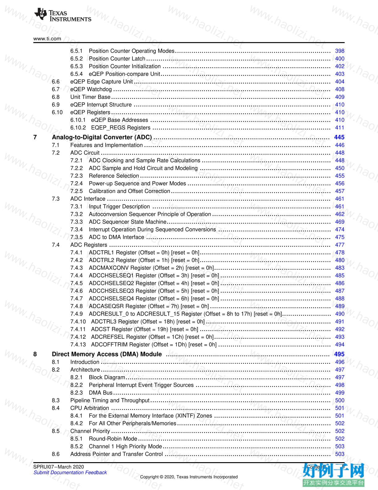
5 SPRUI07–March 2020
Submit Documentation Feedback
Copyright © 2020, Texas Instruments Incorporated
Contents
6.5.1 Position Counter Operating Modes ............................................................................ 398
6.5.2 Position Counter Latch .......................................................................................... 400
6.5.3 Position Counter Initialization .................................................................................. 402
6.5.4 eQEP Position-compare Unit ................................................................................... 403
6.6 eQEP Edge Capture Unit ................................................................................................ 404
6.7 eQEP Watchdog .......................................................................................................... 408
6.8 Unit Timer Base ........................................................................................................... 409
6.9 eQEP Interrupt Structure ................................................................................................ 410
6.10 eQEP Registers ........................................................................................................... 410
6.10.1 eQEP Base Addresses ........................................................................................ 410
6.10.2 EQEP_REGS Registers ....................................................................................... 411
7 Analog-to-Digital Converter (ADC) ...................................................................................... 445
7.1 Features and Implementation ........................................................................................... 446
7.2 ADC Circuit ................................................................................................................ 448
7.2.1 ADC Clocking and Sample Rate Calculations ............................................................... 448
7.2.2 ADC Sample and Hold Circuit and Modeling ................................................................ 450
7.2.3 Reference Selection ............................................................................................. 455
7.2.4 Power-up Sequence and Power Modes ...................................................................... 456
7.2.5 Calibration and Offset Correction .............................................................................. 457
7.3 ADC Interface ............................................................................................................. 461
7.3.1 Input Trigger Description ....................................................................................... 461
7.3.2 Autoconversion Sequencer Principle of Operation .......................................................... 462
7.3.3 ADC Sequencer State Machine ................................................................................ 469
7.3.4 Interrupt Operation During Sequenced Conversions ....................................................... 474
7.3.5 ADC to DMA Interface .......................................................................................... 475
7.4 ADC Registers ............................................................................................................ 477
7.4.1 ADCTRL1 Register (Offset = 0h) [reset = 0h] ................................................................ 478
7.4.2 ADCTRL2 Register (Offset = 1h) [reset = 0h] ................................................................ 480
7.4.3 ADCMAXCONV Register (Offset = 2h) [reset = 0h] ......................................................... 483
7.4.4 ADCCHSELSEQ1 Register (Offset = 3h) [reset = 0h] ...................................................... 485
7.4.5 ADCCHSELSEQ2 Register (Offset = 4h) [reset = 0h] ...................................................... 486
7.4.6 ADCCHSELSEQ3 Register (Offset = 5h) [reset = 0h] ...................................................... 487
7.4.7 ADCCHSELSEQ4 Register (Offset = 6h) [reset = 0h] ...................................................... 488
7.4.8 ADCASEQSR Register (Offset = 7h) [reset = 0h] ........................................................... 489
7.4.9 ADCRESULT_0 to ADCRESULT_15 Register (Offset = 8h to 17h) [reset = 0h] ........................ 490
7.4.10 ADCTRL3 Register (Offset = 18h) [reset = 0h] ............................................................. 491
7.4.11 ADCST Register (Offset = 19h) [reset = 0h] ................................................................ 492
7.4.12 ADCREFSEL Register (Offset = 1Ch) [reset = 0h] ......................................................... 493
7.4.13 ADCOFFTRIM Register (Offset = 1Dh) [reset = 0h] ....................................................... 494
8 Direct Memory Access (DMA) Module ................................................................................ 495
8.1 Introduction ................................................................................................................ 496
8.2 Architecture ................................................................................................................ 497
8.2.1 Block Diagram .................................................................................................... 497
8.2.2 Peripheral Interrupt Event Trigger Sources .................................................................. 498
8.2.3 DMA Bus .......................................................................................................... 499
8.3 Pipeline Timing and Throughput ........................................................................................ 500
8.4 CPU Arbitration ........................................................................................................... 501
8.4.1 For the External Memory Interface (XINTF) Zones ......................................................... 501
8.4.2 For All Other Peripherals/Memories ........................................................................... 502
8.5 Channel Priority ........................................................................................................... 502
8.5.1 Round-Robin Mode .............................................................................................. 502
8.5.2 Channel 1 High Priority Mode .................................................................................. 503
8.6 Address Pointer and Transfer Control ................................................................................. 503
www.ti.com
6 SPRUI07–March 2020
Submit Documentation Feedback
Copyright © 2020, Texas Instruments Incorporated
Contents
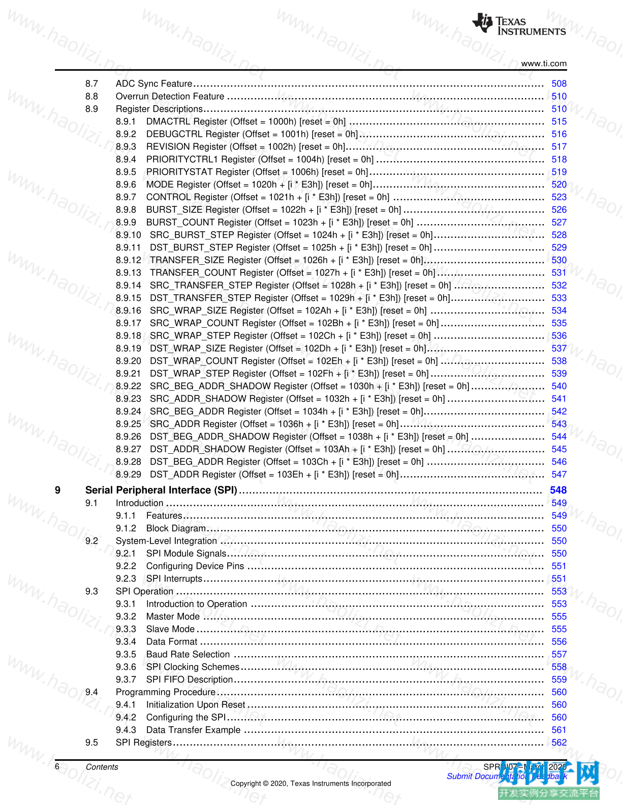
8.7 ADC Sync Feature ........................................................................................................ 508
8.8 Overrun Detection Feature .............................................................................................. 510
8.9 Register Descriptions ..................................................................................................... 510
8.9.1 DMACTRL Register (Offset = 1000h) [reset = 0h] .......................................................... 515
8.9.2 DEBUGCTRL Register (Offset = 1001h) [reset = 0h] ....................................................... 516
8.9.3 REVISION Register (Offset = 1002h) [reset = 0h] ........................................................... 517
8.9.4 PRIORITYCTRL1 Register (Offset = 1004h) [reset = 0h] .................................................. 518
8.9.5 PRIORITYSTAT Register (Offset = 1006h) [reset = 0h] .................................................... 519
8.9.6 MODE Register (Offset = 1020h [i * E3h]) [reset = 0h] ................................................... 520
8.9.7 CONTROL Register (Offset = 1021h [i * E3h]) [reset = 0h] ............................................. 523
8.9.8 BURST_SIZE Register (Offset = 1022h [i * E3h]) [reset = 0h] .......................................... 526
8.9.9 BURST_COUNT Register (Offset = 1023h [i * E3h]) [reset = 0h] ...................................... 527
8.9.10 SRC_BURST_STEP Register (Offset = 1024h [i * E3h]) [reset = 0h] ................................. 528
8.9.11 DST_BURST_STEP Register (Offset = 1025h [i * E3h]) [reset = 0h] ................................. 529
8.9.12 TRANSFER_SIZE Register (Offset = 1026h [i * E3h]) [reset = 0h] .................................... 530
8.9.13 TRANSFER_COUNT Register (Offset = 1027h [i * E3h]) [reset = 0h] ................................ 531
8.9.14 SRC_TRANSFER_STEP Register (Offset = 1028h [i * E3h]) [reset = 0h] ........................... 532
8.9.15 DST_TRANSFER_STEP Register (Offset = 1029h [i * E3h]) [reset = 0h] ............................ 533
8.9.16 SRC_WRAP_SIZE Register (Offset = 102Ah [i * E3h]) [reset = 0h] .................................. 534
8.9.17 SRC_WRAP_COUNT Register (Offset = 102Bh [i * E3h]) [reset = 0h] ............................... 535
8.9.18 SRC_WRAP_STEP Register (Offset = 102Ch [i * E3h]) [reset = 0h] ................................. 536
8.9.19 DST_WRAP_SIZE Register (Offset = 102Dh [i * E3h]) [reset = 0h] ................................... 537
8.9.20 DST_WRAP_COUNT Register (Offset = 102Eh [i * E3h]) [reset = 0h] ............................... 538
8.9.21 DST_WRAP_STEP Register (Offset = 102Fh [i * E3h]) [reset = 0h] .................................. 539
8.9.22 SRC_BEG_ADDR_SHADOW Register (Offset = 1030h [i * E3h]) [reset = 0h] ...................... 540
8.9.23 SRC_ADDR_SHADOW Register (Offset = 1032h [i * E3h]) [reset = 0h] ............................. 541
8.9.24 SRC_BEG_ADDR Register (Offset = 1034h [i * E3h]) [reset = 0h] .................................... 542
8.9.25 SRC_ADDR Register (Offset = 1036h [i * E3h]) [reset = 0h] ........................................... 543
8.9.26 DST_BEG_ADDR_SHADOW Register (Offset = 1038h [i * E3h]) [reset = 0h] ...................... 544
8.9.27 DST_ADDR_SHADOW Register (Offset = 103Ah [i * E3h]) [reset = 0h] ............................. 545
8.9.28 DST_BEG_ADDR Register (Offset = 103Ch [i * E3h]) [reset = 0h] ................................... 546
8.9.29 DST_ADDR Register (Offset = 103Eh [i * E3h]) [reset = 0h] ........................................... 547
9 Serial Peripheral Interface (SPI) .......................................................................................... 548
9.1 Introduction ................................................................................................................ 549
9.1.1 Features ........................................................................................................... 549
9.1.2 Block Diagram .................................................................................................... 550
9.2 System-Level Integration ................................................................................................ 550
9.2.1 SPI Module Signals .............................................................................................. 550
9.2.2 Configuring Device Pins ........................................................................................ 551
9.2.3 SPI Interrupts ..................................................................................................... 551
9.3 SPI Operation ............................................................................................................. 553
9.3.1 Introduction to Operation ....................................................................................... 553
9.3.2 Master Mode ..................................................................................................... 555
9.3.3 Slave Mode ....................................................................................................... 555
9.3.4 Data Format ...................................................................................................... 556
9.3.5 Baud Rate Selection ............................................................................................ 557
9.3.6 SPI Clocking Schemes .......................................................................................... 558
9.3.7 SPI FIFO Description ............................................................................................ 559
9.4 Programming Procedure ................................................................................................. 560
9.4.1 Initialization Upon Reset ........................................................................................ 560
9.4.2 Configuring the SPI .............................................................................................. 560
9.4.3 Data Transfer Example ......................................................................................... 561
9.5 SPI Registers .............................................................................................................. 562
www.ti.com
7 SPRUI07–March 2020
Submit Documentation Feedback
Copyright © 2020, Texas Instruments Incorporated
Contents
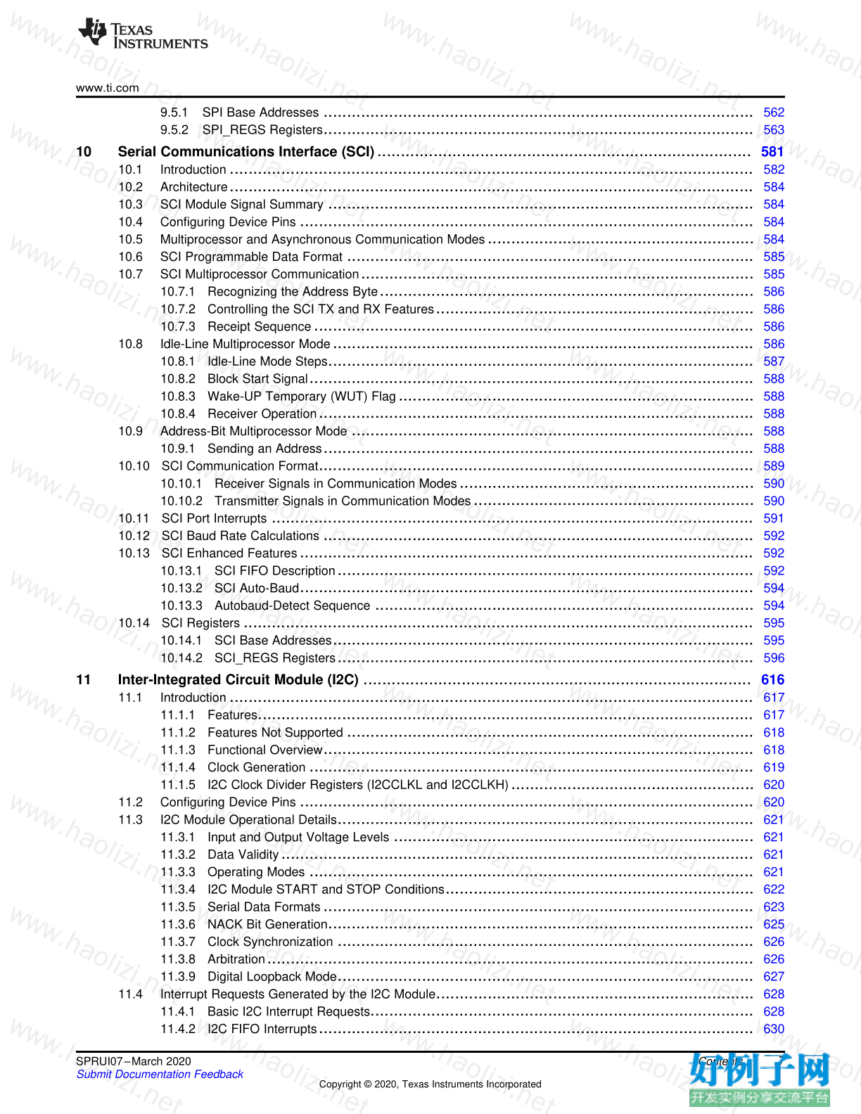
9.5.1 SPI Base Addresses ............................................................................................ 562
9.5.2 SPI_REGS Registers ............................................................................................ 563
10 Serial Communications Interface (SCI) ................................................................................ 581
10.1 Introduction ................................................................................................................ 582
10.2 Architecture ................................................................................................................ 584
10.3 SCI Module Signal Summary ........................................................................................... 584
10.4 Configuring Device Pins ................................................................................................. 584
10.5 Multiprocessor and Asynchronous Communication Modes ......................................................... 584
10.6 SCI Programmable Data Format ....................................................................................... 585
10.7 SCI Multiprocessor Communication .................................................................................... 585
10.7.1 Recognizing the Address Byte ................................................................................ 586
10.7.2 Controlling the SCI TX and RX Features .................................................................... 586
10.7.3 Receipt Sequence .............................................................................................. 586
10.8 Idle-Line Multiprocessor Mode .......................................................................................... 586
10.8.1 Idle-Line Mode Steps ........................................................................................... 587
10.8.2 Block Start Signal ............................................................................................... 588
10.8.3 Wake-UP Temporary (WUT) Flag ............................................................................ 588
10.8.4 Receiver Operation ............................................................................................. 588
10.9 Address-Bit Multiprocessor Mode ...................................................................................... 588
10.9.1 Sending an Address ............................................................................................ 588
10.10 SCI Communication Format ............................................................................................. 589
10.10.1 Receiver Signals in Communication Modes ............................................................... 590
10.10.2 Transmitter Signals in Communication Modes ............................................................ 590
10.11 SCI Port Interrupts ....................................................................................................... 591
10.12 SCI Baud Rate Calculations ............................................................................................ 592
10.13 SCI Enhanced Features ................................................................................................. 592
10.13.1 SCI FIFO Description ......................................................................................... 592
10.13.2 SCI Auto-Baud ................................................................................................. 594
10.13.3 Autobaud-Detect Sequence ................................................................................. 594
10.14 SCI Registers ............................................................................................................. 595
10.14.1 SCI Base Addresses .......................................................................................... 595
10.14.2 SCI_REGS Registers ......................................................................................... 596
11 Inter-Integrated Circuit Module (I2C) ................................................................................... 616
11.1 Introduction ................................................................................................................ 617
11.1.1 Features .......................................................................................................... 617
11.1.2 Features Not Supported ....................................................................................... 618
11.1.3 Functional Overview ............................................................................................ 618
11.1.4 Clock Generation ............................................................................................... 619
11.1.5 I2C Clock Divider Registers (I2CCLKL and I2CCLKH) .................................................... 620
11.2 Configuring Device Pins ................................................................................................. 620
11.3 I2C Module Operational Details ......................................................................................... 621
11.3.1 Input and Output Voltage Levels ............................................................................. 621
11.3.2 Data Validity ..................................................................................................... 621
11.3.3 Operating Modes ............................................................................................... 621
11.3.4 I2C Module START and STOP Conditions .................................................................. 622
11.3.5 Serial Data Formats ............................................................................................ 623
11.3.6 NACK Bit Generation ........................................................................................... 625
11.3.7 Clock Synchronization ......................................................................................... 626
11.3.8 Arbitration ........................................................................................................ 626
11.3.9 Digital Loopback Mode ......................................................................................... 627
11.4 Interrupt Requests Generated by the I2C Module .................................................................... 628
11.4.1 Basic I2C Interrupt Requests .................................................................................. 628
11.4.2 I2C FIFO Interrupts ............................................................................................. 630
www.ti.com
8 SPRUI07–March 2020
Submit Documentation Feedback
Copyright © 2020, Texas Instruments Incorporated
Contents
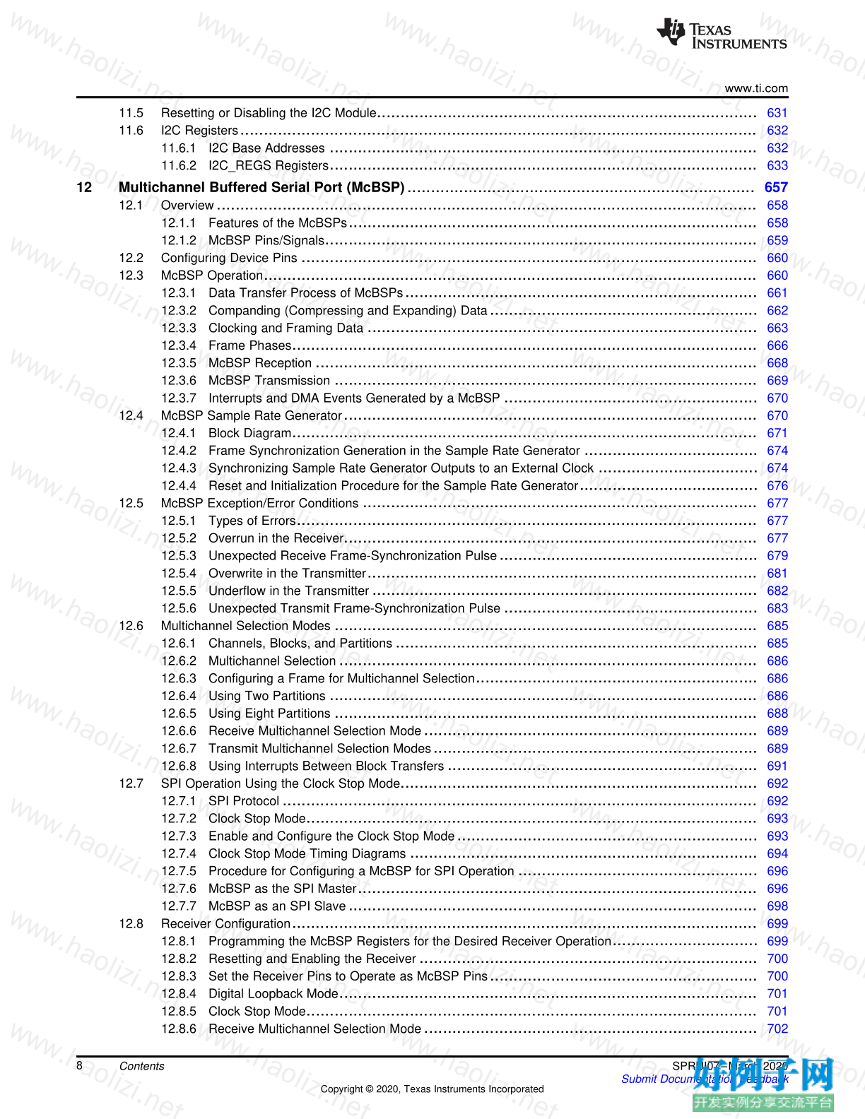
11.5 Resetting or Disabling the I2C Module ................................................................................. 631
11.6 I2C Registers .............................................................................................................. 632
11.6.1 I2C Base Addresses ........................................................................................... 632
11.6.2 I2C_REGS Registers ........................................................................................... 633
12 Multichannel Buffered Serial Port (McBSP) .......................................................................... 657
12.1 Overview ................................................................................................................... 658
12.1.1 Features of the McBSPs ....................................................................................... 658
12.1.2 McBSP Pins/Signals ............................................................................................ 659
12.2 Configuring Device Pins ................................................................................................. 660
12.3 McBSP Operation ......................................................................................................... 660
12.3.1 Data Transfer Process of McBSPs ........................................................................... 661
12.3.2 Companding (Compressing and Expanding) Data ......................................................... 662
12.3.3 Clocking and Framing Data ................................................................................... 663
12.3.4 Frame Phases ................................................................................................... 666
12.3.5 McBSP Reception .............................................................................................. 668
12.3.6 McBSP Transmission .......................................................................................... 669
12.3.7 Interrupts and DMA Events Generated by a McBSP ...................................................... 670
12.4 McBSP Sample Rate Generator ........................................................................................ 670
12.4.1 Block Diagram ................................................................................................... 671
12.4.2 Frame Synchronization Generation in the Sample Rate Generator ..................................... 674
12.4.3 Synchronizing Sample Rate Generator Outputs to an External Clock .................................. 674
12.4.4 Reset and Initialization Procedure for the Sample Rate Generator ...................................... 676
12.5 McBSP Exception/Error Conditions .................................................................................... 677
12.5.1 Types of Errors .................................................................................................. 677
12.5.2 Overrun in the Receiver ........................................................................................ 677
12.5.3 Unexpected Receive Frame-Synchronization Pulse ....................................................... 679
12.5.4 Overwrite in the Transmitter ................................................................................... 681
12.5.5 Underflow in the Transmitter .................................................................................. 682
12.5.6 Unexpected Transmit Frame-Synchronization Pulse ...................................................... 683
12.6 Multichannel Selection Modes .......................................................................................... 685
12.6.1 Channels, Blocks, and Partitions ............................................................................. 685
12.6.2 Multichannel Selection ......................................................................................... 686
12.6.3 Configuring a Frame for Multichannel Selection ............................................................ 686
12.6.4 Using Two Partitions ........................................................................................... 686
12.6.5 Using Eight Partitions .......................................................................................... 688
12.6.6 Receive Multichannel Selection Mode ....................................................................... 689
12.6.7 Transmit Multichannel Selection Modes ..................................................................... 689
12.6.8 Using Interrupts Between Block Transfers .................................................................. 691
12.7 SPI Operation Using the Clock Stop Mode ............................................................................ 692
12.7.1 SPI Protocol ..................................................................................................... 692
12.7.2 Clock Stop Mode ................................................................................................ 693
12.7.3 Enable and Configure the Clock Stop Mode ................................................................ 693
12.7.4 Clock Stop Mode Timing Diagrams .......................................................................... 694
12.7.5 Procedure for Configuring a McBSP for SPI Operation ................................................... 696
12.7.6 McBSP as the SPI Master ..................................................................................... 696
12.7.7 McBSP as an SPI Slave ....................................................................................... 698
12.8 Receiver Configuration ................................................................................................... 699
12.8.1 Programming the McBSP Registers for the Desired Receiver Operation ............................... 699
12.8.2 Resetting and Enabling the Receiver ........................................................................ 700
12.8.3 Set the Receiver Pins to Operate as McBSP Pins ......................................................... 700
12.8.4 Digital Loopback Mode ......................................................................................... 701
12.8.5 Clock Stop Mode ................................................................................................ 701
12.8.6 Receive Multichannel Selection Mode ....................................................................... 702
www.ti.com
9 SPRUI07–March 2020
Submit Documentation Feedback
Copyright © 2020, Texas Instruments Incorporated
Contents
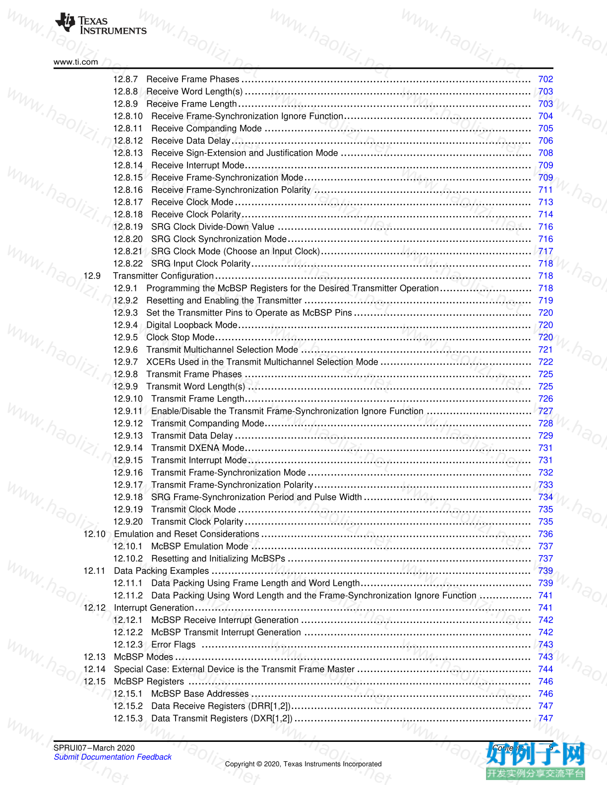
12.8.7 Receive Frame Phases ........................................................................................ 702
12.8.8 Receive Word Length(s) ....................................................................................... 703
12.8.9 Receive Frame Length ......................................................................................... 703
12.8.10 Receive Frame-Synchronization Ignore Function ......................................................... 704
12.8.11 Receive Companding Mode ................................................................................. 705
12.8.12 Receive Data Delay ........................................................................................... 706
12.8.13 Receive Sign-Extension and Justification Mode .......................................................... 708
12.8.14 Receive Interrupt Mode ....................................................................................... 709
12.8.15 Receive Frame-Synchronization Mode ..................................................................... 709
12.8.16 Receive Frame-Synchronization Polarity .................................................................. 711
12.8.17 Receive Clock Mode .......................................................................................... 713
12.8.18 Receive Clock Polarity ........................................................................................ 714
12.8.19 SRG Clock Divide-Down Value ............................................................................. 716
12.8.20 SRG Clock Synchronization Mode .......................................................................... 716
12.8.21 SRG Clock Mode (Choose an Input Clock) ................................................................ 717
12.8.22 SRG Input Clock Polarity ..................................................................................... 718
12.9 Transmitter Configuration ................................................................................................ 718
12.9.1 Programming the McBSP Registers for the Desired Transmitter Operation ............................ 718
12.9.2 Resetting and Enabling the Transmitter ..................................................................... 719
12.9.3 Set the Transmitter Pins to Operate as McBSP Pins ...................................................... 720
12.9.4 Digital Loopback Mode ......................................................................................... 720
12.9.5 Clock Stop Mode ................................................................................................ 720
12.9.6 Transmit Multichannel Selection Mode ...................................................................... 721
12.9.7 XCERs Used in the Transmit Multichannel Selection Mode .............................................. 722
12.9.8 Transmit Frame Phases ....................................................................................... 725
12.9.9 Transmit Word Length(s) ...................................................................................... 725
12.9.10 Transmit Frame Length ....................................................................................... 726
12.9.11 Enable/Disable the Transmit Frame-Synchronization Ignore Function ................................ 727
12.9.12 Transmit Companding Mode ................................................................................. 728
12.9.13 Transmit Data Delay .......................................................................................... 729
12.9.14 Transmit DXENA Mode ....................................................................................... 731
12.9.15 Transmit Interrupt Mode ...................................................................................... 731
12.9.16 Transmit Frame-Synchronization Mode .................................................................... 732
12.9.17 Transmit Frame-Synchronization Polarity .................................................................. 733
12.9.18 SRG Frame-Synchronization Period and Pulse Width ................................................... 734
12.9.19 Transmit Clock Mode ......................................................................................... 735
12.9.20 Transmit Clock Polarity ....................................................................................... 735
12.10 Emulation and Reset Considerations .................................................................................. 736
12.10.1 McBSP Emulation Mode ..................................................................................... 737
12.10.2 Resetting and Initializing McBSPs .......................................................................... 737
12.11 Data Packing Examples ................................................................................................. 739
12.11.1 Data Packing Using Frame Length and Word Length .................................................... 739
12.11.2 Data Packing Using Word Length and the Frame-Synchronization Ignore Function ................ 741
12.12 Interrupt Generation ...................................................................................................... 741
12.12.1 McBSP Receive Interrupt Generation ...................................................................... 742
12.12.2 McBSP Transmit Interrupt Generation ..................................................................... 742
12.12.3 Error Flags .................................................................................................... 743
12.13 McBSP Modes ............................................................................................................ 743
12.14 Special Case: External Device is the Transmit Frame Master ..................................................... 744
12.15 McBSP Registers ........................................................................................................ 746
12.15.1 McBSP Base Addresses ..................................................................................... 746
12.15.2 Data Receive Registers (DRR[1,2]) ......................................................................... 747
12.15.3 Data Transmit Registers (DXR[1,2]) ........................................................................ 747
www.ti.com
10 SPRUI07–March 2020
Submit Documentation Feedback
Copyright © 2020, Texas Instruments Incorporated
Contents
12.15.4 Serial Port Control Registers (SPCR[1,2]) ................................................................. 748
12.15.5 Receive Control Registers (RCR[1, 2]) .................................................................... 753
12.15.6 Transmit Control Registers (XCR1 and XCR2) ........................................................... 755
12.15.7 Sample Rate Generator Registers (SRGR1 and SRGR2) ............................................... 758
12.15.8 Multichannel Control Registers (MCR[1,2]) ................................................................ 760
12.15.9 Pin Control Register (PCR) .................................................................................. 765
12.15.10 Receive Channel Enable Registers (RCERA, RCERB, RCERC, RCERD, RCERE, RCERF,
RCERG, RCERH) ............................................................................................... 767
12.15.11 Transmit Channel Enable Registers (XCERA, XCERB, XCERC, XCERD, XCERE, XCERF,
XCERG, XCERH) ................................................................................................ 769
12.15.12 XCERs Used in a Transmit Multichannel Selection Mode ............................................. 770
12.15.13 McBSP Interrupt Enable Register ......................................................................... 771
12.16 Register to Driverlib Function Mapping ................................................................................ 772
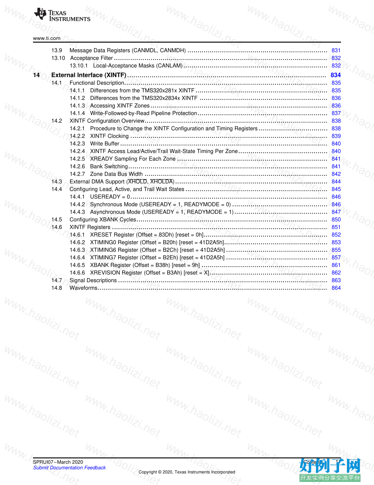
13 Controller Area Network (CAN) ........................................................................................... 773
13.1 CAN Overview ............................................................................................................. 774
13.1.1 Features .......................................................................................................... 774
13.1.2 Block Diagram ................................................................................................... 774
13.2 eCAN Compatibility With Other TI CAN Modules .................................................................... 775
13.3 The CAN Network and Module ......................................................................................... 776
13.3.1 CAN Protocol Overview ........................................................................................ 776
13.4 eCAN Controller Overview ............................................................................................... 778
13.4.1 Standard CAN Controller (SCC) Mode ...................................................................... 778
13.4.2 Memory Map .................................................................................................... 779
13.5 Message Objects ......................................................................................................... 782
13.6 Message Mailbox ......................................................................................................... 782
13.6.1 Transmit Mailbox ................................................................................................ 786
13.6.2 Receive Mailbox ................................................................................................ 787
13.6.3 CAN Module Operation in Normal Configuration ........................................................... 787
13.7 eCAN Configuration ...................................................................................................... 787
13.7.1 CAN Module Initialization ...................................................................................... 787
13.7.2 Steps to Configure eCAN ...................................................................................... 791
13.7.3 Handling of Remote Frame Mailboxes ....................................................................... 793
13.7.4 Interrupts ......................................................................................................... 794
13.7.5 CAN Power-Down Mode ....................................................................................... 799
13.8 eCAN Registers ........................................................................................................... 801
13.8.1 Mailbox Enable Register (CANME) .......................................................................... 801
13.8.2 Mailbox-Direction Register (CANMD) ........................................................................ 802
13.8.3 Transmission-Request Set Register (CANTRS) ............................................................ 803
13.8.4 Transmission-Request-Reset Register (CANTRR) ......................................................... 804
13.8.5 Transmission-Acknowledge Register (CANTA) ............................................................. 804
13.8.6 Abort-Acknowledge Register (CANAA) ...................................................................... 805
13.8.7 Received-Message-Pending Register (CANRMP) ......................................................... 805
13.8.8 Received-Message-Lost Register (CANRML) .............................................................. 806
13.8.9 Remote-Frame-Pending Register (CANRFP) ............................................................... 806
13.8.10 Global Acceptance Mask Register (CANGAM) ........................................................... 808
13.8.11 Master Control Register (CANMC) .......................................................................... 809
13.8.12 Bit-Timing Configuration Register (CANBTC) ............................................................. 812
13.8.13 Error and Status Register (CANES) ........................................................................ 814
13.8.14 CAN Error Counter Registers (CANTEC/CANREC) ...................................................... 816
13.8.15 Interrupt Registers ............................................................................................ 817
13.8.16 Overwrite Protection Control Register (CANOPC) ........................................................ 822
13.8.17 eCAN I/O Control Registers (CANTIOC, CANRIOC) ..................................................... 823
13.8.18 Timer Management Unit ...................................................................................... 825
13.8.19 Mailbox Layout ................................................................................................ 829
www.ti.com
11 SPRUI07–March 2020
Submit Documentation Feedback
Copyright © 2020, Texas Instruments Incorporated
Contents
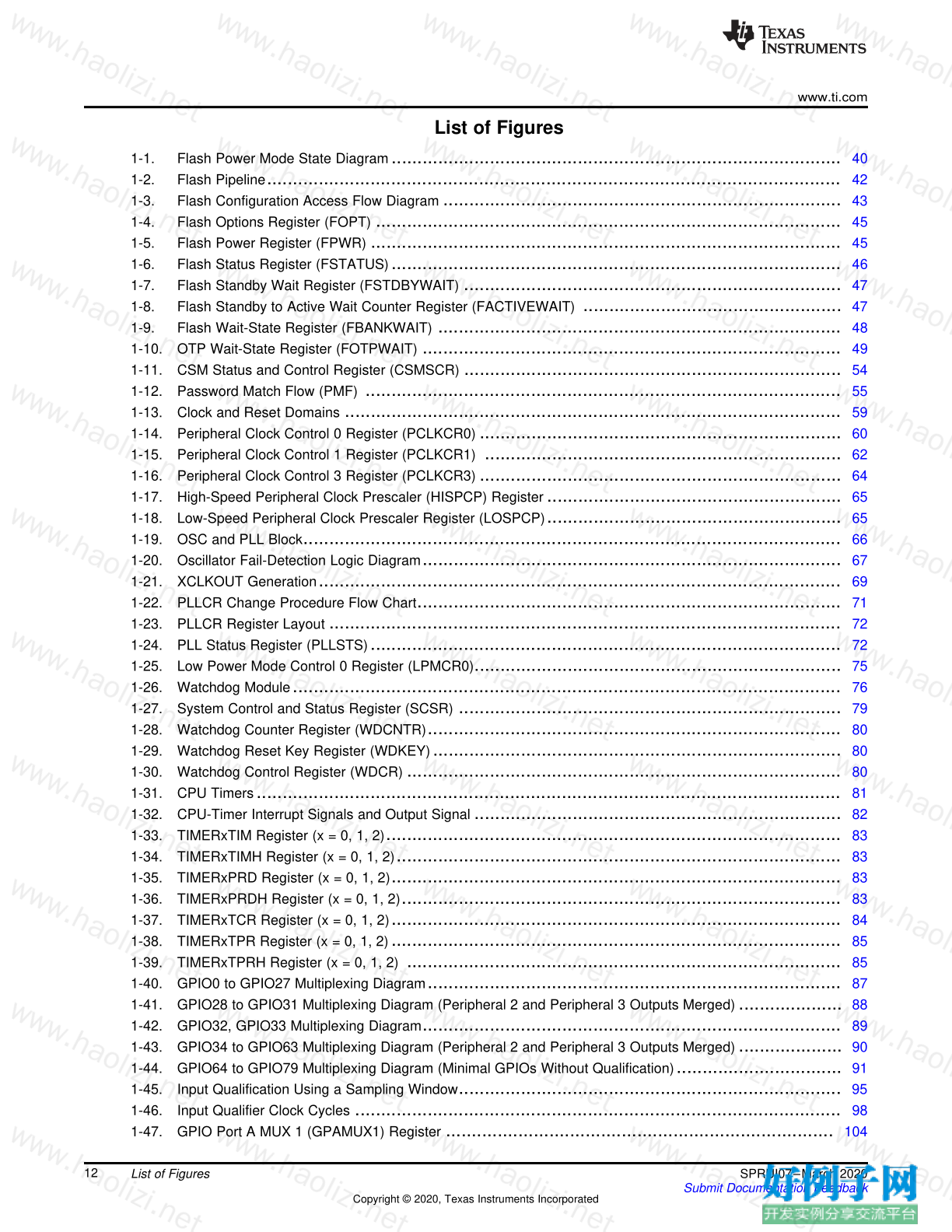
13.9 Message Data Registers (CANMDL, CANMDH) ..................................................................... 831
13.10 Acceptance Filter ......................................................................................................... 832
13.10.1 Local-Acceptance Masks (CANLAM) ....................................................................... 832
14 External Interface (XINTF) .................................................................................................. 834
14.1 Functional Description .................................................................................................... 835
14.1.1 Differences from the TMS320x281x XINTF ................................................................. 835
14.1.2 Differences from the TMS320x2834x XINTF ............................................................... 836
14.1.3 Accessing XINTF Zones ....................................................................................... 836
14.1.4 Write-Followed-by-Read Pipeline Protection ................................................................ 837
14.2 XINTF Configuration Overview .......................................................................................... 838
14.2.1 Procedure to Change the XINTF Configuration and Timing Registers .................................. 838
14.2.2 XINTF Clocking ................................................................................................. 839
14.2.3 Write Buffer ...................................................................................................... 840
14.2.4 XINTF Access Lead/Active/Trail Wait-State Timing Per Zone ............................................ 840
14.2.5 XREADY Sampling For Each Zone .......................................................................... 841
14.2.6 Bank Switching .................................................................................................. 841
14.2.7 Zone Data Bus Width .......................................................................................... 842
14.3 External DMA Support (XHOLD, XHOLDA) ........................................................................... 844
14.4 Configuring Lead, Active, and Trail Wait States ...................................................................... 845
14.4.1 USEREADY = 0 ................................................................................................. 846
14.4.2 Synchronous Mode (USEREADY = 1, READYMODE = 0) ............................................... 846
14.4.3 Asynchronous Mode (USEREADY = 1, READYMODE = 1) .............................................. 847
14.5 Configuring XBANK Cycles .............................................................................................. 850
14.6 XINTF Registers .......................................................................................................... 851
14.6.1 XRESET Register (Offset = 83Dh) [reset = 0h] ............................................................. 852
14.6.2 XTIMING0 Register (Offset = B20h) [reset = 41D2A5h] ................................................... 853
14.6.3 XTIMING6 Register (Offset = B2Ch) [reset = 41D2A5h] .................................................. 855
14.6.4 XTIMING7 Register (Offset = B2Eh) [reset = 41D2A5h] .................................................. 857
14.6.5 XBANK Register (Offset = B38h) [reset = 9h] .............................................................. 861
14.6.6 XREVISION Register (Offset = B3Ah) [reset = X] .......................................................... 862
14.7 Signal Descriptions ....................................................................................................... 863
14.8 Waveforms ................................................................................................................. 864
www.ti.com
12 SPRUI07–March 2020
Submit Documentation Feedback
Copyright © 2020, Texas Instruments Incorporated
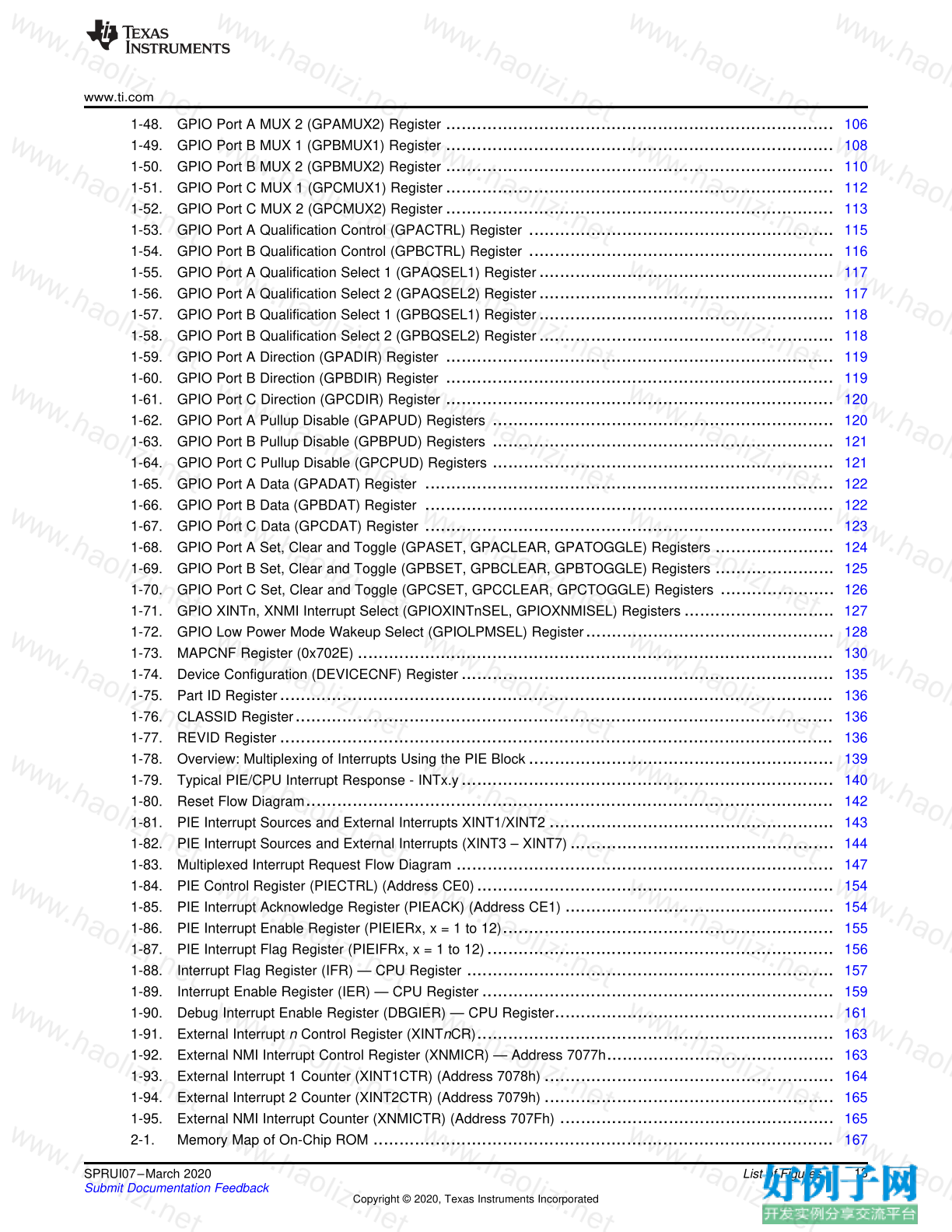
List of Figures
List of Figures
1-1. Flash Power Mode State Diagram ....................................................................................... 40
1-2. Flash Pipeline ............................................................................................................... 42
1-3. Flash Configuration Access Flow Diagram ............................................................................. 43
1-4. Flash Options Register (FOPT) .......................................................................................... 45
1-5. Flash Power Register (FPWR) ........................................................................................... 45
1-6. Flash Status Register (FSTATUS) ....................................................................................... 46
1-7. Flash Standby Wait Register (FSTDBYWAIT) ......................................................................... 47
1-8. Flash Standby to Active Wait Counter Register (FACTIVEWAIT) .................................................. 47
1-9. Flash Wait-State Register (FBANKWAIT) .............................................................................. 48
1-10. OTP Wait-State Register (FOTPWAIT) ................................................................................. 49
1-11. CSM Status and Control Register (CSMSCR) ......................................................................... 54
1-12. Password Match Flow (PMF) ............................................................................................ 55
1-13. Clock and Reset Domains ................................................................................................ 59
1-14. Peripheral Clock Control 0 Register (PCLKCR0) ...................................................................... 60
1-15. Peripheral Clock Control 1 Register (PCLKCR1) ..................................................................... 62
1-16. Peripheral Clock Control 3 Register (PCLKCR3) ...................................................................... 64
1-17. High-Speed Peripheral Clock Prescaler (HISPCP) Register ......................................................... 65
1-18. Low-Speed Peripheral Clock Prescaler Register (LOSPCP) ......................................................... 65
1-19. OSC and PLL Block ........................................................................................................ 66
1-20. Oscillator Fail-Detection Logic Diagram ................................................................................. 67
1-21. XCLKOUT Generation ..................................................................................................... 69
1-22. PLLCR Change Procedure Flow Chart .................................................................................. 71
1-23. PLLCR Register Layout ................................................................................................... 72
1-24. PLL Status Register (PLLSTS) ........................................................................................... 72
1-25. Low Power Mode Control 0 Register (LPMCR0) ....................................................................... 75
1-26. Watchdog Module .......................................................................................................... 76
1-27. System Control and Status Register (SCSR) .......................................................................... 79
1-28. Watchdog Counter Register (WDCNTR) ................................................................................ 80
1-29. Watchdog Reset Key Register (WDKEY) ............................................................................... 80
1-30. Watchdog Control Register (WDCR) .................................................................................... 80
1-31. CPU Timers ................................................................................................................. 81
1-32. CPU-Timer Interrupt Signals and Output Signal ....................................................................... 82
1-33. TIMERxTIM Register (x = 0, 1, 2) ........................................................................................ 83
1-34. TIMERxTIMH Register (x = 0, 1, 2) ...................................................................................... 83
1-35. TIMERxPRD Register (x = 0, 1, 2) ....................................................................................... 83
1-36. TIMERxPRDH Register (x = 0, 1, 2) ..................................................................................... 83
1-37. TIMERxTCR Register (x = 0, 1, 2) ....................................................................................... 84
1-38. TIMERxTPR Register (x = 0, 1, 2) ....................................................................................... 85
1-39. TIMERxTPRH Register (x = 0, 1, 2) .................................................................................... 85
1-40. GPIO0 to GPIO27 Multiplexing Diagram ................................................................................ 87
1-41. GPIO28 to GPIO31 Multiplexing Diagram (Peripheral 2 and Peripheral 3 Outputs Merged) .................... 88
1-42. GPIO32, GPIO33 Multiplexing Diagram ................................................................................. 89
1-43. GPIO34 to GPIO63 Multiplexing Diagram (Peripheral 2 and Peripheral 3 Outputs Merged) .................... 90
1-44. GPIO64 to GPIO79 Multiplexing Diagram (Minimal GPIOs Without Qualification) ................................ 91
1-45. Input Qualification Using a Sampling Window .......................................................................... 95
1-46. Input Qualifier Clock Cycles .............................................................................................. 98
1-47. GPIO Port A MUX 1 (GPAMUX1) Register ........................................................................... 104
www.ti.com
13 SPRUI07–March 2020
Submit Documentation Feedback
Copyright © 2020, Texas Instruments Incorporated
List of Figures
1-48. GPIO Port A MUX 2 (GPAMUX2) Register ........................................................................... 106
1-49. GPIO Port B MUX 1 (GPBMUX1) Register ........................................................................... 108
1-50. GPIO Port B MUX 2 (GPBMUX2) Register ........................................................................... 110
1-51. GPIO Port C MUX 1 (GPCMUX1) Register ........................................................................... 112
1-52. GPIO Port C MUX 2 (GPCMUX2) Register ........................................................................... 113
1-53. GPIO Port A Qualification Control (GPACTRL) Register ........................................................... 115
1-54. GPIO Port B Qualification Control (GPBCTRL) Register ........................................................... 116
1-55. GPIO Port A Qualification Select 1 (GPAQSEL1) Register ......................................................... 117
1-56. GPIO Port A Qualification Select 2 (GPAQSEL2) Register ......................................................... 117
1-57. GPIO Port B Qualification Select 1 (GPBQSEL1) Register ......................................................... 118
1-58. GPIO Port B Qualification Select 2 (GPBQSEL2) Register ......................................................... 118
1-59. GPIO Port A Direction (GPADIR) Register ........................................................................... 119
1-60. GPIO Port B Direction (GPBDIR) Register ........................................................................... 119
1-61. GPIO Port C Direction (GPCDIR) Register ........................................................................... 120
1-62. GPIO Port A Pullup Disable (GPAPUD) Registers .................................................................. 120
1-63. GPIO Port B Pullup Disable (GPBPUD) Registers .................................................................. 121
1-64. GPIO Port C Pullup Disable (GPCPUD) Registers .................................................................. 121
1-65. GPIO Port A Data (GPADAT) Register ............................................................................... 122
1-66. GPIO Port B Data (GPBDAT) Register ............................................................................... 122
1-67. GPIO Port C Data (GPCDAT) Register ............................................................................... 123
1-68. GPIO Port A Set, Clear and Toggle (GPASET, GPACLEAR, GPATOGGLE) Registers ....................... 124
1-69. GPIO Port B Set, Clear and Toggle (GPBSET, GPBCLEAR, GPBTOGGLE) Registers ....................... 125
1-70. GPIO Port C Set, Clear and Toggle (GPCSET, GPCCLEAR, GPCTOGGLE) Registers ...................... 126
1-71. GPIO XINTn, XNMI Interrupt Select (GPIOXINTnSEL, GPIOXNMISEL) Registers ............................. 127
1-72. GPIO Low Power Mode Wakeup Select (GPIOLPMSEL) Register ................................................ 128
1-73. MAPCNF Register (0x702E) ............................................................................................ 130
1-74. Device Configuration (DEVICECNF) Register ........................................................................ 135
1-75. Part ID Register ........................................................................................................... 136
1-76. CLASSID Register ........................................................................................................ 136
1-77. REVID Register ........................................................................................................... 136
1-78. Overview: Multiplexing of Interrupts Using the PIE Block ........................................................... 139
1-79. Typical PIE/CPU Interrupt Response - INTx.y ........................................................................ 140
1-80. Reset Flow Diagram ...................................................................................................... 142
1-81. PIE Interrupt Sources and External Interrupts XINT1/XINT2 ....................................................... 143
1-82. PIE Interrupt Sources and External Interrupts (XINT3 – XINT7) ................................................... 144
1-83. Multiplexed Interrupt Request Flow Diagram ......................................................................... 147
1-84. PIE Control Register (PIECTRL) (Address CE0) ..................................................................... 154
1-85. PIE Interrupt Acknowledge Register (PIEACK) (Address CE1) .................................................... 154
1-86. PIE Interrupt Enable Register (PIEIERx, x = 1 to 12) ................................................................ 155
1-87. PIE Interrupt Flag Register (PIEIFRx, x = 1 to 12) ................................................................... 156
1-88. Interrupt Flag Register (IFR) — CPU Register ....................................................................... 157
1-89. Interrupt Enable Register (IER) — CPU Register .................................................................... 159
1-90. Debug Interrupt Enable Register (DBGIER) — CPU Register ...................................................... 161
1-91. External Interrupt n Control Register (XINTnCR) ..................................................................... 163
1-92. External NMI Interrupt Control Register (XNMICR) — Address 7077h ............................................ 163
1-93. External Interrupt 1 Counter (XINT1CTR) (Address 7078h) ........................................................ 164
1-94. External Interrupt 2 Counter (XINT2CTR) (Address 7079h) ........................................................ 165
1-95. External NMI Interrupt Counter (XNMICTR) (Address 707Fh) ..................................................... 165
2-1. Memory Map of On-Chip ROM ......................................................................................... 167
www.ti.com
14 SPRUI07–March 2020
Submit Documentation Feedback
Copyright © 2020, Texas Instruments Incorporated
List of Figures
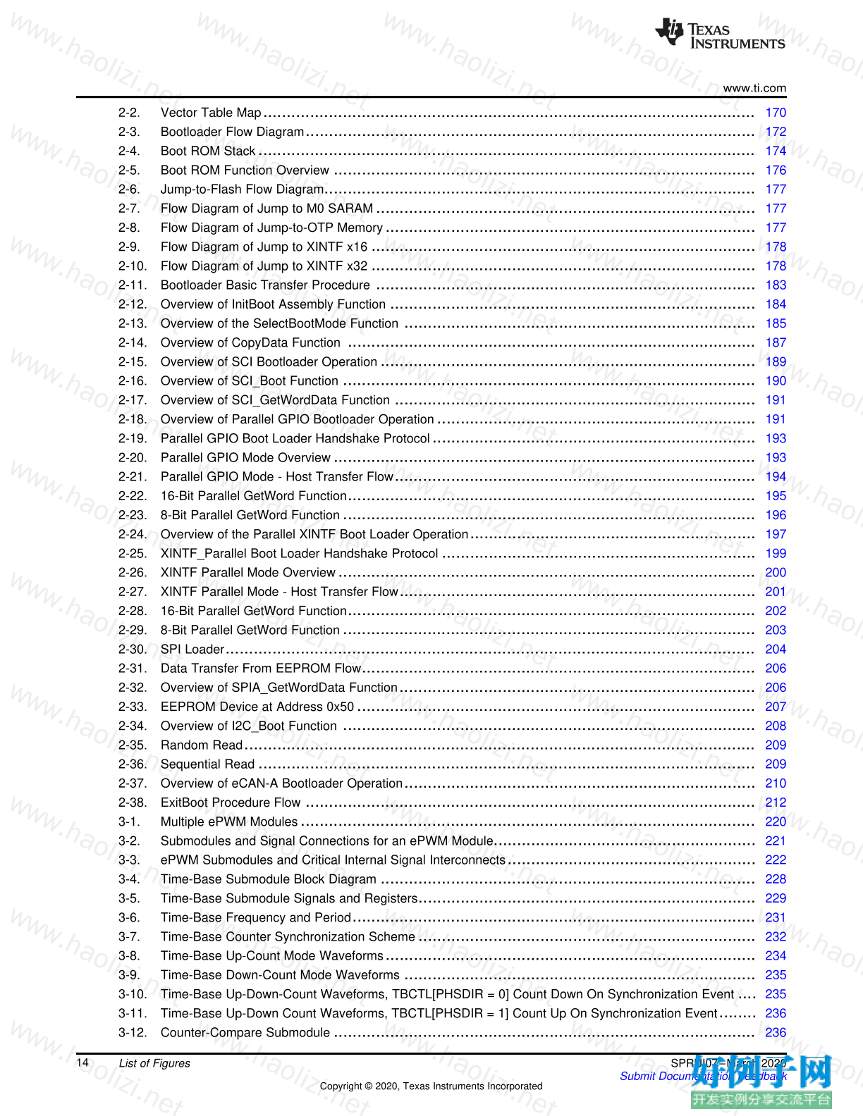
2-2. Vector Table Map ......................................................................................................... 170
2-3. Bootloader Flow Diagram ................................................................................................ 172
2-4. Boot ROM Stack .......................................................................................................... 174
2-5. Boot ROM Function Overview .......................................................................................... 176
2-6. Jump-to-Flash Flow Diagram ............................................................................................ 177
2-7. Flow Diagram of Jump to M0 SARAM ................................................................................. 177
2-8. Flow Diagram of Jump-to-OTP Memory ............................................................................... 177
2-9. Flow Diagram of Jump to XINTF x16 .................................................................................. 178
2-10. Flow Diagram of Jump to XINTF x32 .................................................................................. 178
2-11. Bootloader Basic Transfer Procedure ................................................................................. 183
2-12. Overview of InitBoot Assembly Function .............................................................................. 184
2-13. Overview of the SelectBootMode Function ........................................................................... 185
2-14. Overview of CopyData Function ....................................................................................... 187
2-15. Overview of SCI Bootloader Operation ................................................................................ 189
2-16. Overview of SCI_Boot Function ........................................................................................ 190
2-17. Overview of SCI_GetWordData Function ............................................................................. 191
2-18. Overview of Parallel GPIO Bootloader Operation .................................................................... 191
2-19. Parallel GPIO Boot Loader Handshake Protocol ..................................................................... 193
2-20. Parallel GPIO Mode Overview .......................................................................................... 193
2-21. Parallel GPIO Mode - Host Transfer Flow ............................................................................. 194
2-22. 16-Bit Parallel GetWord Function ....................................................................................... 195
2-23. 8-Bit Parallel GetWord Function ........................................................................................ 196
2-24. Overview of the Parallel XINTF Boot Loader Operation ............................................................. 197
2-25. XINTF_Parallel Boot Loader Handshake Protocol ................................................................... 199
2-26. XINTF Parallel Mode Overview ......................................................................................... 200
2-27. XINTF Parallel Mode - Host Transfer Flow ............................................................................ 201
2-28. 16-Bit Parallel GetWord Function ....................................................................................... 202
2-29. 8-Bit Parallel GetWord Function ........................................................................................ 203
2-30. SPI Loader ................................................................................................................. 204
2-31. Data Transfer From EEPROM Flow .................................................................................... 206
2-32. Overview of SPIA_GetWordData Function ............................................................................ 206
2-33. EEPROM Device at Address 0x50 ..................................................................................... 207
2-34. Overview of I2C_Boot Function ........................................................................................ 208
2-35. Random Read ............................................................................................................. 209
2-36. Sequential Read .......................................................................................................... 209
2-37. Overview of eCAN-A Bootloader Operation ........................................................................... 210
2-38. ExitBoot Procedure Flow ................................................................................................ 212
3-1. Multiple ePWM Modules ................................................................................................. 220
3-2. Submodules and Signal Connections for an ePWM Module ........................................................ 221
3-3. ePWM Submodules and Critical Internal Signal Interconnects ..................................................... 222
3-4. Time-Base Submodule Block Diagram ................................................................................ 228
3-5. Time-Base Submodule Signals and Registers ........................................................................ 229
3-6. Time-Base Frequency and Period ...................................................................................... 231
3-7. Time-Base Counter Synchronization Scheme ........................................................................ 232
3-8. Time-Base Up-Count Mode Waveforms ............................................................................... 234
3-9. Time-Base Down-Count Mode Waveforms ........................................................................... 235
3-10. Time-Base Up-Down-Count Waveforms, TBCTL[PHSDIR = 0] Count Down On Synchronization Event .... 235
3-11. Time-Base Up-Down Count Waveforms, TBCTL[PHSDIR = 1] Count Up On Synchronization Event ........ 236
3-12. Counter-Compare Submodule .......................................................................................... 236
www.ti.com
15 SPRUI07–March 2020
Submit Documentation Feedback
Copyright © 2020, Texas Instruments Incorporated
List of Figures
3-13. Detailed View of the Counter-Compare Submodule ................................................................. 237
3-14. Counter-Compare Event Waveforms in Up-Count Mode ............................................................ 239
3-15. Counter-Compare Events in Down-Count Mode ..................................................................... 240
3-16. Counter-Compare Events In Up-Down-Count Mode, TBCTL[PHSDIR = 0] Count Down On
Synchronization Event ................................................................................................... 240
3-17. Counter-Compare Events In Up-Down-Count Mode, TBCTL[PHSDIR = 1] Count Up On Synchronization
Event ....................................................................................................................... 241
3-18. Action-Qualifier Submodule ............................................................................................. 242
3-19. Action-Qualifier Submodule Inputs and Outputs ...................................................................... 243
3-20. Possible Action-Qualifier Actions for EPWMxA and EPWMxB Outputs ........................................... 244
3-21. Up-Down-Count Mode Symmetrical Waveform ....................................................................... 247
3-22. Up, Single Edge Asymmetric Waveform, With Independent Modulation on EPWMxA and
EPWMxB—Active High .................................................................................................. 248
3-23. Up, Single Edge Asymmetric Waveform With Independent Modulation on EPWMxA and
EPWMxB—Active Low ................................................................................................... 250
3-24. Up-Count, Pulse Placement Asymmetric Waveform With Independent Modulation on EPWMxA ............. 251
3-25. Up-Down-Count, Dual Edge Symmetric Waveform, With Independent Modulation on EPWMxA and
EPWMxB — Active Low ................................................................................................. 253
3-26. Up-Down-Count, Dual Edge Symmetric Waveform, With Independent Modulation on EPWMxA and
EPWMxB — Complementary ........................................................................................... 254
3-27. Up-Down-Count, Dual Edge Asymmetric Waveform, With Independent Modulation on EPWMxA—Active
Low ......................................................................................................................... 255
3-28. Dead_Band Submodule .................................................................................................. 256
3-29. Configuration Options for the Dead-Band Submodule ............................................................... 257
3-30. Dead-Band Waveforms for Typical Cases (0% < Duty < 100%) ................................................... 259
3-31. PWM-Chopper Submodule .............................................................................................. 261
3-32. PWM-Chopper Submodule Operational Details ...................................................................... 262
3-33. Simple PWM-Chopper Submodule Waveforms Showing Chopping Action Only ................................ 262
3-34. PWM-Chopper Submodule Waveforms Showing the First Pulse and Subsequent Sustaining Pulses ....... 263
3-35. PWM-Chopper Submodule Waveforms Showing the Pulse Width (Duty Cycle) Control of Sustaining
Pulses ...................................................................................................................... 264
3-36. Trip-Zone Submodule .................................................................................................... 265
3-37. Trip-Zone Submodule Mode Control Logic ............................................................................ 268
3-38. Trip-Zone Submodule Interrupt Logic .................................................................................. 269
3-39. Event-Trigger Submodule ............................................................................................... 269
3-40. Event-Trigger Submodule Inter-Connectivity of ADC Start of Conversion ........................................ 270
3-41. Event-Trigger Submodule Showing Event Inputs and Prescaled Outputs ........................................ 271
3-42. Event-Trigger Interrupt Generator ...................................................................................... 272
3-43. Event-Trigger SOCA Pulse Generator ................................................................................. 273
3-44. Event-Trigger SOCB Pulse Generator ................................................................................. 273
3-45. Simplified ePWM Module ................................................................................................ 274
3-46. EPWM1 Configured as a Typical Master, EPWM2 Configured as a Slave ...................................... 275
3-47. Control of Four Buck Stages. Here F PWM1 ≠ F PWM2 ≠ F PWM3 ≠ F PWM4 .................................................... 276
3-48. Buck Waveforms for (Note: Only three bucks shown here) ......................................................... 277
3-49. Control of Four Buck Stages. (Note: F PWM2 = N x F PWM1 ) ............................................................. 279
3-50. Buck Waveforms for (Note: F PWM2 = F PWM1) ) ............................................................................ 280
3-51. Control of Two Half-H Bridge Stages (F PWM2 = N x F PWM1 ) ........................................................... 282
3-52. Half-H Bridge Waveforms for (Note: Here F PWM2 = F PWM1 ) ........................................................... 283
3-53. Control of Dual 3-Phase Inverter Stages as Is Commonly Used in Motor Control ............................... 285
3-54. 3-Phase Inverter Waveforms for (Only One Inverter Shown) ....................................................... 286
3-55. Configuring Two PWM Modules for Phase Control .................................................................. 288
www.ti.com
16 SPRUI07–March 2020
Submit Documentation Feedback
Copyright © 2020, Texas Instruments Incorporated
List of Figures
3-56. Timing Waveforms Associated With Phase Control Between 2 Modules ......................................... 289
3-57. Control of a 3-Phase Interleaved DC/DC Converter ................................................................. 290
3-58. 3-Phase Interleaved DC/DC Converter Waveforms for ............................................................. 291
3-59. Controlling a Full-H Bridge Stage (F PWM2 = F PWM1) .................................................................... 293
3-60. ZVS Full-H Bridge Waveforms .......................................................................................... 294
3-61. Time-Base Period Register (TBPRD) .................................................................................. 296
3-62. Time-Base Phase Register (TBPHS) .................................................................................. 296
3-63. Time-Base Counter Register (TBCTR) ................................................................................ 296
3-64. Time-Base Control Register (TBCTL) .................................................................................. 297
3-65. Time-Base Status Register (TBSTS) ................................................................................... 299
3-66. Counter-Compare A Register (CMPA) ................................................................................ 300
3-67. Counter-Compare B Register (CMPB) ................................................................................. 301
3-68. Counter-Compare Control Register (CMPCTL) ....................................................................... 302
3-69. Compare A High Resolution Register (CMPAHR) ................................................................... 303
3-70. Action-Qualifier Output A Control Register (AQCTLA) ............................................................... 304
3-71. Action-Qualifier Output B Control Register (AQCTLB) ............................................................... 305
3-72. Action-Qualifier Software Force Register (AQSFRC) ................................................................ 306
3-73. Action-Qualifier Continuous Software Force Register (AQCSFRC) ................................................ 307
3-74. Dead-Band Generator Control Register (DBCTL) .................................................................... 308
3-75. Dead-Band Generator Rising Edge Delay Register (DBRED) ...................................................... 309
3-76. Dead-Band Generator Falling Edge Delay Register (DBFED) ..................................................... 310
3-77. PWM-Chopper Control Register (PCCTL) ............................................................................. 311
3-78. Trip-Zone Select Register (TZSEL) .................................................................................... 313
3-79. Trip-Zone Control Register (TZCTL) ................................................................................... 315
3-80. Trip-Zone Enable Interrupt Register (TZEINT) ........................................................................ 316
3-81. Trip-Zone Flag Register (TZFLG) ....................................................................................... 317
3-82. Trip-Zone Clear Register (TZCLR) ..................................................................................... 318
3-83. Trip-Zone Force Register (TZFRC) ..................................................................................... 319
3-84. Event-Trigger Selection Register (ETSEL) ............................................................................ 320
3-85. Event-Trigger Prescale Register (ETPS) .............................................................................. 322
3-86. Event-Trigger Flag Register (ETFLG) .................................................................................. 323
3-87. Event-Trigger Clear Register (ETCLR) ................................................................................ 324
3-88. Event-Trigger Force Register (ETFRC) ................................................................................ 325
4-1. Resolution Calculations for Conventionally Generated PWM ....................................................... 327
4-2. Operating Logic Using MEP ............................................................................................. 328
4-3. HRPWM Extension Registers and Memory Configuration .......................................................... 329
4-4. HRPWM System Interface ............................................................................................... 329
4-5. Required PWM Waveform for a Requested Duty = 40.5% ......................................................... 331
4-6. Low % Duty Cycle Range Limitation Example When PWM Frequency = 1 MHz ............................... 334
4-7. High % Duty Cycle Range Limitation Example when PWM Frequency = 1 MHz ............................... 335
4-8. Simple Buck Controlled Converter Using a Single PWM ............................................................ 340
4-9. PWM Waveform Generated for Simple Buck Controlled Converter ............................................... 340
4-10. Simple Reconstruction Filter for a PWM Based DAC ................................................................ 343
4-11. PWM Waveform Generated for the PWM DAC Function ........................................................... 343
4-12. HRPWM Configuration Register (HRCNFG) .......................................................................... 347
4-13. Counter Compare A High-Resolution Register (CMPAHR) ......................................................... 347
4-14. Time Base Phase High-Resolution Register (TBPHSHR) ........................................................... 348
5-1. Multiple eCAP Modules In A C28x System ............................................................................ 352
5-2. Capture and APWM Modes of Operation .............................................................................. 353
www.ti.com
17 SPRUI07–March 2020
Submit Documentation Feedback
Copyright © 2020, Texas Instruments Incorporated
List of Figures
5-3. Counter Compare and PRD Effects on the eCAP Output in APWM Mode ....................................... 354
5-4. eCAP Block Diagram ..................................................................................................... 355
5-5. Event Prescale Control ................................................................................................... 356
5-6. Prescale Function Waveforms .......................................................................................... 356
5-7. Details of the Continuous/One-shot Block ............................................................................. 358
5-8. Details of the Counter and Synchronization Block ................................................................... 359
5-9. Interrupts in eCAP Module .............................................................................................. 361
5-10. PWM Waveform Details Of APWM Mode Operation ................................................................ 362
5-11. Time-Base Frequency and Period Calculation ........................................................................ 363
5-12. Capture Sequence for Absolute Time-stamp and Rising Edge Detect ............................................ 364
5-13. Capture Sequence for Absolute Time-stamp With Rising and Falling Edge Detect ............................. 365
5-14. Capture Sequence for Delta Mode Time-stamp and Rising Edge Detect ......................................... 366
5-15. Capture Sequence for Delta Mode Time-stamp With Rising and Falling Edge Detect .......................... 367
5-16. PWM Waveform Details of APWM Mode Operation ................................................................. 368
5-17. Multi-phase (channel) Interleaved PWM Example Using 3 eCAP Modules ....................................... 369
5-18. TSCTR Register .......................................................................................................... 373
5-19. CTRPHS Register ........................................................................................................ 374
5-20. CAP1 Register ............................................................................................................ 375
5-21. CAP2 Register ............................................................................................................ 376
5-22. CAP3 Register ............................................................................................................ 377
5-23. CAP4 Register ............................................................................................................ 378
5-24. ECCTL1 Register ......................................................................................................... 379
5-25. ECCTL2 Register ......................................................................................................... 381
5-26. ECEINT Register .......................................................................................................... 383
5-27. ECFLG Register .......................................................................................................... 385
5-28. ECCLR Register .......................................................................................................... 387
5-29. ECFRC Register .......................................................................................................... 388
6-1. Optical Encoder Disk ..................................................................................................... 390
6-2. QEP Encoder Output Signal for Forward/Reverse Movement ...................................................... 390
6-3. Index Pulse Example ..................................................................................................... 391
6-4. Functional Block Diagram of the eQEP Peripheral ................................................................... 393
6-5. Functional Block Diagram of Decoder Unit ............................................................................ 395
6-6. Quadrature Decoder State Machine .................................................................................... 396
6-7. Quadrature-clock and Direction Decoding ............................................................................. 397
6-8. Position Counter Reset by Index Pulse for 1000 Line Encoder (QPOSMAX = 3999 or 0xF9F) ............... 399
6-9. Position Counter Underflow/Overflow (QPOSMAX = 4) ............................................................ 400
6-10. Software Index Marker for 1000-line Encoder (QEPCTL[IEL] = 1) ................................................. 401
6-11. Strobe Event Latch (QEPCTL[SEL] = 1) ............................................................................... 402
6-12. eQEP Position-compare Unit ............................................................................................ 403
6-13. eQEP Position-compare Event Generation Points ................................................................... 404
6-14. eQEP Position-compare Sync Output Pulse Stretcher .............................................................. 404
6-15. eQEP Edge Capture Unit ................................................................................................ 406
6-16. Unit Position Event for Low Speed Measurement (QCAPCTL[UPPS] = 0010) .................................. 406
6-17. eQEP Edge Capture Unit - Timing Details ............................................................................ 407
6-18. eQEP Watchdog Timer .................................................................................................. 408
6-19. eQEP Unit Time Base .................................................................................................... 409
6-20. EQEP Interrupt Generation .............................................................................................. 410
6-21. QPOSCNT Register ...................................................................................................... 413
6-22. QPOSINIT Register ....................................................................................................... 414
www.ti.com
18 SPRUI07–March 2020
Submit Documentation Feedback
Copyright © 2020, Texas Instruments Incorporated
List of Figures
6-23. QPOSMAX Register ...................................................................................................... 415
6-24. QPOSCMP Register ...................................................................................................... 416
6-25. QPOSILAT Register ...................................................................................................... 417
6-26. QPOSSLAT Register ..................................................................................................... 418
6-27. QPOSLAT Register ....................................................................................................... 419
6-28. QUTMR Register .......................................................................................................... 420
6-29. QUPRD Register .......................................................................................................... 421
6-30. QWDTMR Register ....................................................................................................... 422
6-31. QWDPRD Register ....................................................................................................... 423
6-32. QDECCTL Register ....................................................................................................... 424
6-33. QEPCTL Register ......................................................................................................... 426
6-34. QCAPCTL Register ....................................................................................................... 429
6-35. QPOSCTL Register ....................................................................................................... 430
6-36. QEINT Register ........................................................................................................... 431
6-37. QFLG Register ............................................................................................................ 433
6-38. QCLR Register ............................................................................................................ 435
6-39. QFRC Register ............................................................................................................ 437
6-40. QEPSTS Register ........................................................................................................ 439
6-41. QCTMR Register .......................................................................................................... 441
6-42. QCPRD Register .......................................................................................................... 442
6-43. QCTMRLAT Register ..................................................................................................... 443
6-44. QCPRDLAT Register ..................................................................................................... 444
7-1. Block Diagram of the ADC Module ..................................................................................... 446
7-2. ADC Core Clock and Sample-and-Hold (S/H) Clock ................................................................. 448
7-3. Clock Chain to the ADC .................................................................................................. 448
7-4. ADCINx Input Model ...................................................................................................... 450
7-5. External Bias for 2.048-V External Reference ........................................................................ 455
7-6. Flow Chart of Offset Error Correction Process ....................................................................... 459
7-7. Ideal Code Distribution of Sampled 0-V Reference .................................................................. 460
7-8. Block Diagram of Autosequenced ADC in Cascaded Mode ........................................................ 463
7-9. Block Diagram of Autosequenced ADC With Dual Sequencers .................................................... 464
7-10. Sequential Sampling Mode (SMODE = 0) ............................................................................. 466
7-11. Simultaneous Sampling Mode (SMODE = 1) ......................................................................... 467
7-12. Flow Chart for Uninterrupted Autosequenced Mode ................................................................. 471
7-13. Example of ePWM Triggers to Start the Sequencer ................................................................ 472
7-14. Interrupt Operation During Sequenced Conversions ................................................................ 475
7-15. ADCTRL1 Register ....................................................................................................... 478
7-16. ADCTRL2 Register ....................................................................................................... 480
7-17. ADCMAXCONV Register ................................................................................................ 483
7-18. ADCCHSELSEQ1 Register .............................................................................................. 485
7-19. ADCCHSELSEQ2 Register .............................................................................................. 486
7-20. ADCCHSELSEQ3 Register .............................................................................................. 487
7-21. ADCCHSELSEQ4 Register .............................................................................................. 488
7-22. ADCASEQSR Register .................................................................................................. 489
7-23. ADCRESULT_0 to ADCRESULT_15 Register ....................................................................... 490
7-24. ADCRESULT_0 to ADCRESULT_15 Register (Addresses 0x0B00-0x0B0F) .................................... 490
7-25. ADCTRL3 Register ....................................................................................................... 491
7-26. ADCST Register .......................................................................................................... 492
7-27. ADCREFSEL Register ................................................................................................... 493
www.ti.com
19 SPRUI07–March 2020
Submit Documentation Feedback
Copyright © 2020, Texas Instruments Incorporated
List of Figures
7-28. ADCOFFTRIM Register .................................................................................................. 494
8-1. DMA Block Diagram ...................................................................................................... 497
8-2. Peripheral Interrupt Trigger Input Diagram ............................................................................ 498
8-3. 4-Stage Pipeline DMA Transfer ......................................................................................... 500
8-4. 4-Stage Pipeline With One Read Stall (McBSP as source) ......................................................... 500
8-5. DMA State Diagram ...................................................................................................... 507
8-6. ADC Sync Input Diagram ................................................................................................ 509
8-7. Overrun Detection Logic ................................................................................................. 510
8-8. DMACTRL Register ...................................................................................................... 515
8-9. DEBUGCTRL Register ................................................................................................... 516
8-10. REVISION Register ....................................................................................................... 517
8-11. PRIORITYCTRL1 Register .............................................................................................. 518
8-12. PRIORITYSTAT Register ................................................................................................ 519
8-13. MODE Register ........................................................................................................... 520
8-14. CONTROL Register ...................................................................................................... 523
8-15. BURST_SIZE Register ................................................................................................... 526
8-16. BURST_COUNT Register ............................................................................................... 527
8-17. SRC_BURST_STEP Register ........................................................................................... 528
8-18. DST_BURST_STEP Register ........................................................................................... 529
8-19. TRANSFER_SIZE Register ............................................................................................. 530
8-20. TRANSFER_COUNT Register .......................................................................................... 531
8-21. SRC_TRANSFER_STEP Register ..................................................................................... 532
8-22. DST_TRANSFER_STEP Register ..................................................................................... 533
8-23. SRC_WRAP_SIZE Register ............................................................................................. 534
8-24. SRC_WRAP_COUNT Register ......................................................................................... 535
8-25. SRC_WRAP_STEP Register ............................................................................................ 536
8-26. DST_WRAP_SIZE Register ............................................................................................. 537
8-27. DST_WRAP_COUNT Register ......................................................................................... 538
8-28. DST_WRAP_STEP Register ............................................................................................ 539
8-29. SRC_BEG_ADDR_SHADOW Register ................................................................................ 540
8-30. SRC_ADDR_SHADOW Register ....................................................................................... 541
8-31. SRC_BEG_ADDR Register ............................................................................................. 542
8-32. SRC_ADDR Register ..................................................................................................... 543
8-33. DST_BEG_ADDR_SHADOW Register ................................................................................ 544
8-34. DST_ADDR_SHADOW Register ....................................................................................... 545
8-35. DST_BEG_ADDR Register .............................................................................................. 546
8-36. DST_ADDR Register ..................................................................................................... 547
9-1. SPI CPU Interface ........................................................................................................ 550
9-2. SPI Interrupt Flags and Enable Logic Generation .................................................................... 552
9-3. SPI Master/Slave Connection ........................................................................................... 553
9-4. Serial Peripheral Interface Block Diagram ............................................................................. 554
9-5. SPICLK Signal Options .................................................................................................. 558
9-6. SPI: SPICLK-LSPCLK Characteristic When (BRR 1) is Odd, BRR > 3, and CLKPOLARITY = 1 ........... 559
9-7. Five Bits per Character ................................................................................................... 561
9-8. SPICCR Register ......................................................................................................... 564
9-9. SPICTL Register .......................................................................................................... 566
9-10. SPISTS Register .......................................................................................................... 568
9-11. SPIBRR Register ......................................................................................................... 570
9-12. SPIRXEMU Register ..................................................................................................... 571
www.ti.com
20 SPRUI07–March 2020
Submit Documentation Feedback
Copyright © 2020, Texas Instruments Incorporated
List of Figures
9-13. SPIRXBUF Register ...................................................................................................... 572
9-14. SPITXBUF Register ...................................................................................................... 573
9-15. SPIDAT Register .......................................................................................................... 574
9-16. SPIFFTX Register ........................................................................................................ 575
9-17. SPIFFRX Register ........................................................................................................ 577
9-18. SPIFFCT Register ........................................................................................................ 579
9-19. SPIPRI Register ........................................................................................................... 580
10-1. SCI CPU Interface ........................................................................................................ 582
10-2. Serial Communications Interface (SCI) Module Block Diagram .................................................... 583
10-3. Typical SCI Data Frame Formats ....................................................................................... 585
10-4. Idle-Line Multiprocessor Communication Format ..................................................................... 587
10-5. Double-Buffered WUT and TXSHF ..................................................................................... 588
10-6. Address-Bit Multiprocessor Communication Format ................................................................. 589
10-7. SCI Asynchronous Communications Format .......................................................................... 590
10-8. SCI RX Signals in Communication Modes ............................................................................ 590
10-9. SCI TX Signals in Communications Mode ............................................................................ 591
10-10. SCI FIFO Interrupt Flags and Enable Logic ........................................................................... 593
10-11. SCICCR Register ......................................................................................................... 597
10-12. SCICTL1 Register ........................................................................................................ 599
10-13. SCIHBAUD Register ..................................................................................................... 601
10-14. SCILBAUD Register ...................................................................................................... 602
10-15. SCICTL2 Register ........................................................................................................ 603
10-16. SCIRXST Register ........................................................................................................ 605
10-17. SCIRXEMU Register ..................................................................................................... 607
10-18. SCIRXBUF Register ...................................................................................................... 608
10-19. SCITXBUF Register ...................................................................................................... 609
10-20. SCIFFTX Register ........................................................................................................ 610
10-21. SCIFFRX Register ........................................................................................................ 612
10-22. SCIFFCT Register ........................................................................................................ 614
10-23. SCIPRI Register .......................................................................................................... 615
11-1. Multiple I2C Modules Connected ....................................................................................... 617
11-2. I2C Module Conceptual Block Diagram ................................................................................ 619
11-3. Clocking Diagram for the I2C Module .................................................................................. 619
11-4. The Roles of the Clock Divide-Down Values (ICCL and ICCH) .................................................... 620
11-5. Bit Transfer on the I2C bus .............................................................................................. 621
11-6. I2C Module START and STOP Conditions ............................................................................ 623
11-7. I2C Module Data Transfer (7-Bit Addressing with 8-bit Data Configuration Shown) ............................. 624
11-8. I2C Module 7-Bit Addressing Format (FDF = 0, XA = 0 in I2CMDR) .............................................. 624
11-9. I2C Module 10-Bit Addressing Format (FDF = 0, XA = 1 in I2CMDR) ............................................ 624
11-10. I2C Module Free Data Format (FDF = 1 in I2CMDR) ................................................................ 625
11-11. Repeated START Condition (in This Case, 7-Bit Addressing Format) ............................................ 625
11-12. Synchronization of Two I2C Clock Generators During Arbitration ................................................. 626
11-13. Arbitration Procedure Between Two Master-Transmitters ........................................................... 627
11-14. Pin Diagram Showing the Effects of the Digital Loopback Mode (DLB) Bit ....................................... 628
11-15. Enable Paths of the I2C Interrupt Requests .......................................................................... 629
11-16. Backwards Compatibility Mode Bit, Slave Transmitter ............................................................... 630
11-17. I2C_FIFO_interrupt ....................................................................................................... 631
11-18. I2COAR Register ......................................................................................................... 634
11-19. I2CIER Register ........................................................................................................... 635
www.ti.com
21 SPRUI07–March 2020
Submit Documentation Feedback
Copyright © 2020, Texas Instruments Incorporated
List of Figures
11-20. I2CSTR Register .......................................................................................................... 636
11-21. I2CCLKL Register ........................................................................................................ 640
11-22. I2CCLKH Register ........................................................................................................ 641
11-23. I2CCNT Register .......................................................................................................... 642
11-24. I2CDRR Register ......................................................................................................... 643
11-25. I2CSAR Register .......................................................................................................... 644
11-26. I2CDXR Register .......................................................................................................... 645
11-27. I2CMDR Register ......................................................................................................... 646
11-28. I2CISRC Register ......................................................................................................... 650
11-29. I2CEMDR Register ....................................................................................................... 651
11-30. I2CPSC Register .......................................................................................................... 652
11-31. I2CFFTX Register ........................................................................................................ 653
11-32. I2CFFRX Register ........................................................................................................ 655
12-1. Conceptual Block Diagram of the McBSP ............................................................................. 660
12-2. McBSP Data Transfer Paths ............................................................................................ 661
12-3. Companding Processes .................................................................................................. 662
12-4. μ-Law Transmit Data Companding Format ............................................................................ 662
12-5. A-Law Transmit Data Companding Format ........................................................................... 662
12-6. Two Methods by Which the McBSP Can Compand Internal Data ................................................. 663
12-7. Example - Clock Signal Control of Bit Transfer Timing .............................................................. 663
12-8. McBSP Operating at Maximum Packet Frequency .................................................................. 665
12-9. Single-Phase Frame for a McBSP Data Transfer .................................................................... 666
12-10. Dual-Phase Frame for a McBSP Data Transfer ...................................................................... 667
12-11. Implementing the AC97 Standard With a Dual-Phase Frame ...................................................... 667
12-12. Timing of an AC97-Standard Data Transfer Near Frame Synchronization ....................................... 668
12-13. McBSP Reception Physical Data Path ................................................................................. 668
12-14. McBSP Reception Signal Activity ....................................................................................... 668
12-15. McBSP Transmission Physical Data Path ............................................................................. 669
12-16. McBSP Transmission Signal Activity ................................................................................... 669
12-17. Conceptual Block Diagram of the Sample Rate Generator ......................................................... 671
12-18. Possible Inputs to the Sample Rate Generator and the Polarity Bits .............................................. 673
12-19. CLKG Synchronization and FSG Generation When GSYNC = 1 and CLKGDV = 1 ............................ 675
12-20. CLKG Synchronization and FSG Generation When GSYNC = 1 and CLKGDV = 3 ............................ 676
12-21. Overrun in the McBSP Receiver ........................................................................................ 678
12-22. Overrun Prevented in the McBSP Receiver ........................................................................... 679
12-23. Possible Responses to Receive Frame-Synchronization Pulses ................................................... 679
12-24. An Unexpected Frame-Synchronization Pulse During a McBSP Reception ...................................... 680
12-25. Proper Positioning of Frame-Synchronization Pulses ................................................................ 681
12-26. Data in the McBSP Transmitter Overwritten and Thus Not Transmitted .......................................... 681
12-27. Underflow During McBSP Transmission ............................................................................... 682
12-28. Underflow Prevented in the McBSP Transmitter ..................................................................... 683
12-29. Possible Responses to Transmit Frame-Synchronization Pulses .................................................. 683
12-30. An Unexpected Frame-Synchronization Pulse During a McBSP Transmission .................................. 684
12-31. Proper Positioning of Frame-Synchronization Pulses ................................................................ 685
12-32. Alternating Between the Channels of Partition A and the Channels of Partition B .............................. 687
12-33. Reassigning Channel Blocks Throughout a McBSP Data Transfer ................................................ 688
12-34. McBSP Data Transfer in the 8-Partition Mode ........................................................................ 689
12-35. Activity on McBSP Pins for the Possible Values of XMCM ......................................................... 692
12-36. Typical SPI Interface ..................................................................................................... 693
www.ti.com
22 SPRUI07–March 2020
Submit Documentation Feedback
Copyright © 2020, Texas Instruments Incorporated
List of Figures
12-37. SPI Transfer With CLKSTP = 10b (No Clock Delay), CLKXP = 0, and CLKRP = 0 ............................. 695
12-38. SPI Transfer With CLKSTP = 11b (Clock Delay), CLKXP = 0, CLKRP = 1 ...................................... 695
12-39. SPI Transfer With CLKSTP = 10b (No Clock Delay), CLKXP = 1, and CLKRP = 0 ............................. 695
12-40. SPI Transfer With CLKSTP = 11b (Clock Delay), CLKXP = 1, CLKRP = 1 ...................................... 695
12-41. SPI Interface with McBSP Used as Master ........................................................................... 697
12-42. SPI Interface With McBSP Used as Slave ............................................................................ 698
12-43. Unexpected Frame-Synchronization Pulse With (R/X)FIG = 0 ..................................................... 705
12-44. Unexpected Frame-Synchronization Pulse With (R/X)FIG = 1 ..................................................... 705
12-45. Companding Processes for Reception and for Transmission ....................................................... 706
12-46. Range of Programmable Data Delay ................................................................................... 707
12-47. 2-Bit Data Delay Used to Skip a Framing Bit ......................................................................... 707
12-48. Data Clocked Externally Using a Rising Edge and Sampled by the McBSP Receiver on a Falling Edge .... 712
12-49. Frame of Period 16 CLKG Periods and Active Width of 2 CLKG Periods ........................................ 713
12-50. Data Clocked Externally Using a Rising Edge and Sampled by the McBSP Receiver on a Falling Edge .... 715
12-51. Unexpected Frame-Synchronization Pulse With (R/X) FIG = 0 .................................................... 727
12-52. Unexpected Frame-Synchronization Pulse With (R/X) FIG = 1 .................................................... 728
12-53. Companding Processes for Reception and for Transmission ....................................................... 728
12-54. μ-Law Transmit Data Companding Format ............................................................................ 729
12-55. A-Law Transmit Data Companding Format ........................................................................... 729
12-56. Range of Programmable Data Delay ................................................................................... 730
12-57. 2-Bit Data Delay Used to Skip a Framing Bit ......................................................................... 730
12-58. Data Clocked Externally Using a Rising Edge and Sampled by the McBSP Receiver on a Falling Edge .... 734
12-59. Frame of Period 16 CLKG Periods and Active Width of 2 CLKG Periods ........................................ 734
12-60. Data Clocked Externally Using a Rising Edge and Sampled by the McBSP Receiver on a Falling Edge .... 736
12-61. Four 8-Bit Data Words Transferred To/From the McBSP ........................................................... 740
12-62. One 32-Bit Data Word Transferred To/From the McBSP ........................................................... 740
12-63. 8-Bit Data Words Transferred at Maximum Packet Frequency ..................................................... 741
12-64. Configuring the Data Stream of as a Continuous 32-Bit Word ..................................................... 741
12-65. Receive Interrupt Generation ............................................................................................ 742
12-66. Transmit Interrupt Generation ........................................................................................... 742
12-67. Data Receive Registers (DRR2 and DRR1) .......................................................................... 747
12-68. Data Transmit Registers (DXR2 and DXR1) .......................................................................... 747
12-69. Serial Port Control 1 Register (SPCR1) ............................................................................... 748
12-70. Serial Port Control 2 Register (SPCR2) ............................................................................... 751
12-71. Receive Control Register 1 (RCR1) .................................................................................... 753
12-72. Receive Control Register 2 (RCR2) .................................................................................... 754
12-73. Transmit Control 1 Register (XCR1) ................................................................................... 756
12-74. Transmit Control 2 Register (XCR2) .................................................................................. 757
12-75. Sample Rate Generator 1 Register (SRGR1) ......................................................................... 759
12-76. Sample Rate Generator 2 Register (SRGR2) ......................................................................... 759
12-77. Multichannel Control 1 Register (MCR1) ............................................................................. 761
12-78. Multichannel Control 2 Register (MCR2) .............................................................................. 763
12-79. Pin Control Register (PCR) ............................................................................................. 765
12-80. Receive Channel Enable Registers (RCERA...RCERH) ............................................................ 767
12-81. Transmit Channel Enable Registers (XCERA...XCERH) ............................................................ 769
12-82. McBSP Interrupt Enable Register (MFFINT) .......................................................................... 771
13-1. eCAN Block Diagram and Interface Circuit ............................................................................ 775
13-2. CAN Data Frame ......................................................................................................... 776
13-3. Architecture of the eCAN Module ....................................................................................... 777
www.ti.com
23 SPRUI07–March 2020
Submit Documentation Feedback
Copyright © 2020, Texas Instruments Incorporated
List of Figures
13-4. eCAN-A Memory Map .................................................................................................... 780
13-5. eCAN-B Memory Map .................................................................................................... 781
13-6. Initialization Sequence ................................................................................................... 788
13-7. CAN Bit Timing ............................................................................................................ 789
13-8. Interrupts Scheme ........................................................................................................ 795
13-9. Mailbox-Enable Register (CANME) .................................................................................... 801
13-10. Mailbox-Enable Register (CANME) .................................................................................... 801
13-11. Mailbox-Direction Register (CANMD) .................................................................................. 802
13-12. Transmission-Request Set Register (CANTRS) ...................................................................... 803
13-13. Transmission-Request-Reset Register (CANTRR) ................................................................... 804
13-14. Transmission-Acknowledge Register (CANTA) ....................................................................... 804
13-15. Abort-Acknowledge Register (CANAA) ................................................................................ 805
13-16. Received-Message-Pending Register (CANRMP) ................................................................... 805
13-17. Received-Message-Lost Register (CANRML) ........................................................................ 806
13-18. Remote-Frame-Pending Register (CANRFP) ......................................................................... 806
13-19. Global Acceptance Mask Register (CANGAM) ....................................................................... 808
13-20. Master Control Register (CANMC) ..................................................................................... 809
13-21. Bit-Timing Configuration Register (CANBTC) ......................................................................... 812
13-22. Error and Status Register (CANES) .................................................................................... 814
13-23. Transmit-Error-Counter Register (CANTEC) .......................................................................... 816
13-24. Receive-Error-Counter Register (CANREC) .......................................................................... 816
13-25. Global Interrupt Flag 0 Register (CANGIF0) .......................................................................... 818
13-26. Global Interrupt Flag 1 Register (CANGIF1) .......................................................................... 818
13-27. Global Interrupt Mask Register (CANGIM) ............................................................................ 820
13-28. Mailbox Interrupt Mask Register (CANMIM) .......................................................................... 821
13-29. Mailbox Interrupt Level Register (CANMIL) ........................................................................... 822
13-30. Overwrite Protection Control Register (CANOPC) ................................................................... 822
13-31. TX I/O Control Register (CANTIOC) ................................................................................... 823
13-32. RX I/O Control Register (CANRIOC) ................................................................................... 824
13-33. Time-Stamp Counter Register (CANTSC) ............................................................................. 825
13-34. Message-Object Time-Out Registers (MOTO) ........................................................................ 826
13-35. Message Object Time Stamp Registers (MOTS) ..................................................................... 826
13-36. Time-Out Control Register (CANTOC) ................................................................................. 827
13-37. Time-Out Status Register (CANTOS) .................................................................................. 828
13-38. Message Identifier Register (MSGID) Register ....................................................................... 829
13-39. Message-Control Register (MSGCTRL) ............................................................................... 830
13-40. Message-Data-Low Register With DBO = 0 (CANMDL) ............................................................ 831
13-41. Message-Data-High Register With DBO = 0 (CANMDH) ........................................................... 831
13-42. Message-Data-Low Register With DBO = 1 (CANMDL) ............................................................ 831
13-43. Message-Data-High Register With DBO = 1 (CANMDH) ........................................................... 831
13-44. Local-Acceptance-Mask Register (LAMn) ............................................................................. 833
14-1. External Interface Block Diagram ....................................................................................... 837
14-2. Access Flow Diagram .................................................................................................... 839
14-3. Relationship Between XTIMCLK and SYSCLKOUT ................................................................. 840
14-4. Typical 16-bit Data Bus XINTF Connections .......................................................................... 842
14-5. Typical 32-bit Data Bus XINTF Connections .......................................................................... 843
14-6. XRESET Register ......................................................................................................... 852
14-7. XTIMING0 Register ....................................................................................................... 853
14-8. XTIMING6 Register ....................................................................................................... 855
www.ti.com
24 SPRUI07–March 2020
Submit Documentation Feedback
Copyright © 2020, Texas Instruments Incorporated
List of Figures
14-9. XTIMING7 Register ....................................................................................................... 857
14-10. XBANK Register .......................................................................................................... 861
14-11. XREVISION Register ..................................................................................................... 862
14-12. XTIMCLK and XCLKOUT Mode Waveforms .......................................................................... 864
14-13. Generic Read Cycle (XTIMCLK = SYSCLKOUT mode) ............................................................. 865
14-14. Generic Read Cycle (XTIMCLK = ½ SYSCLKOUT mode) .......................................................... 866
14-15. Generic Write Cycle (XTIMCLK = SYSCLKOUT mode) ............................................................. 867
www.ti.com
25 SPRUI07–March 2020
Submit Documentation Feedback
Copyright © 2020, Texas Instruments Incorporated
List of Tables
List of Tables
1-1. Flash/OTP Configuration Registers ...................................................................................... 44
1-2. Flash Options Register (FOPT) Field Descriptions .................................................................... 45
1-3. Flash Power Register (FPWR) Field Descriptions ..................................................................... 45
1-4. Flash Status Register (FSTATUS) Field Descriptions ................................................................. 46
1-5. Flash Standby Wait Register (FSTDBYWAIT) Field Descriptions ................................................... 47
1-6. Flash Standby to Active Wait Counter Register (FACTIVEWAIT) Field Descriptions ............................. 47
1-7. Flash Wait-State Register (FBANKWAIT) Field Descriptions ........................................................ 48
1-8. OTP Wait-State Register (FOTPWAIT) Field Descriptions ........................................................... 49
1-9. Security Levels ............................................................................................................. 50
1-10. Resources Affected by the CSM ......................................................................................... 52
1-11. Resources Not Affected by the CSM .................................................................................... 52
1-12. Code Security Module (CSM) Registers ................................................................................ 53
1-13. CSM Status and Control Register (CSMSCR) Field Descriptions ................................................... 54
1-14. PLL, Clocking, Watchdog, and Low-Power Mode Registers ........................................................ 60
1-15. Peripheral Clock Control 0 Register (PCLKCR0) Field Descriptions ................................................ 60
1-16. Peripheral Clock Control 1 Register (PCLKCR1) Field Descriptions ............................................... 62
1-17. Peripheral Clock Control 3 Register (PCLKCR3) Field Descriptions ................................................ 64
1-18. High-Speed Peripheral Clock Prescaler (HISPCP) Field Descriptions .............................................. 65
1-19. Low-Speed Peripheral Clock Prescaler Register (LOSPCP) Field Descriptions ................................... 65
1-20. Possible PLL Configuration Modes ...................................................................................... 67
1-21. PLLCR Bit Descriptions ................................................................................................... 72
1-22. PLL Status Register (PLLSTS) Field Descriptions ..................................................................... 73
1-23. Low-Power Mode Summary .............................................................................................. 74
1-24. Low Power Modes ......................................................................................................... 74
1-25. Low Power Mode Control 0 Register (LPMCR0) Field Descriptions ................................................ 75
1-26. Example Watchdog Key Sequences ..................................................................................... 77
1-27. System Control and Status Register (SCSR) Field Descriptions .................................................... 79
1-28. Watchdog Counter Register (WDCNTR) Field Descriptions ......................................................... 80
1-29. Watchdog Reset Key Register (WDKEY) Field Descriptions ......................................................... 80
1-30. Watchdog Control Register (WDCR) Field Descriptions .............................................................. 80
1-31. CPU Timers 0, 1, 2 Configuration and Control Registers ............................................................. 82
1-32. TIMERxTIM Register Field Descriptions ................................................................................ 83
1-33. TIMERxTIMH Register Field Descriptions .............................................................................. 83
1-34. TIMERxPRD Register Field Descriptions ............................................................................... 83
1-35. TIMERxPRDH Register Field Descriptions ............................................................................. 83
1-36. TIMERxTCR Register Field Descriptions ............................................................................... 84
1-37. TIMERxTPR Register Field Descriptions ............................................................................... 85
1-38. TIMERxTPRH Register Field Descriptions .............................................................................. 85
1-39. GPIO Control Registers ................................................................................................... 92
1-40. GPIO Interrupt and Low Power Mode Select Registers ............................................................... 92
1-41. GPIO Data Registers ...................................................................................................... 93
1-42. Sampling Period ............................................................................................................ 96
1-43. Sampling Frequency ....................................................................................................... 96
1-44. Case 1: Three-Sample Sampling Window Width ...................................................................... 97
1-45. Case 2: Six-Sample Sampling Window Width .......................................................................... 97
1-46. Default State of Peripheral Input ........................................................................................ 100
1-47. GPIOA MUX ............................................................................................................... 101
www.ti.com
26 SPRUI07–March 2020
Submit Documentation Feedback
Copyright © 2020, Texas Instruments Incorporated
List of Tables
1-48. GPIOB MUX ............................................................................................................... 102
1-49. GPIOC MUX ............................................................................................................... 103
1-50. GPIO Port A Multiplexing 1 (GPAMUX1) Register Field Descriptions ............................................. 104
1-51. GPIO Port A MUX 2 (GPAMUX2) Register Field Descriptions ..................................................... 106
1-52. GPIO Port B MUX 1 (GPBMUX1) Register Field Descriptions ..................................................... 108
1-53. GPIO Port B MUX 2 (GPBMUX2) Register Field Descriptions ..................................................... 110
1-54. GPIO Port C MUX 1 (GPCMUX1) Register Field Descriptions ..................................................... 112
1-55. GPIO Port C MUX 2 (GPCMUX2) Register Field Descriptions ..................................................... 113
1-56. GPIO Port A Qualification Control (GPACTRL) Register Field Descriptions ..................................... 115
1-57. GPIO Port B Qualification Control (GPBCTRL) Register Field Descriptions ..................................... 116
1-58. GPIO Port A Qualification Select 1 (GPAQSEL1) Register Field Descriptions ................................... 117
1-59. GPIO Port A Qualification Select 2 (GPAQSEL2) Register Field Descriptions ................................... 117
1-60. GPIO Port B Qualification Select 1 (GPBQSEL1) Register Field Descriptions ................................... 118
1-61. GPIO Port B Qualification Select 2 (GPBQSEL2) Register Field Descriptions ................................... 118
1-62. GPIO Port A Direction (GPADIR) Register Field Descriptions ...................................................... 119
1-63. GPIO Port B Direction (GPBDIR) Register Field Descriptions ...................................................... 119
1-64. GPIO Port C Direction (GPCDIR) Register Field Descriptions ..................................................... 120
1-65. GPIO Port A Internal Pullup Disable (GPAPUD) Register Field Descriptions .................................... 120
1-66. GPIO Port B Internal Pullup Disable (GPBPUD) Register Field Descriptions .................................... 121
1-67. GPIO Port C Internal Pullup Disable (GPCPUD) Register Field Descriptions .................................... 121
1-68. GPIO Port A Data (GPADAT) Register Field Descriptions .......................................................... 122
1-69. GPIO Port B Data (GPBDAT) Register Field Descriptions .......................................................... 123
1-70. GPIO Port C Data (GPCDAT) Register Field Descriptions ......................................................... 123
1-71. GPIO Port A Set (GPASET) Register Field Descriptions ............................................................ 124
1-72. GPIO Port A Clear (GPACLEAR) Register Field Descriptions ..................................................... 124
1-73. GPIO Port A Toggle (GPATOGGLE) Register Field Descriptions ................................................. 124
1-74. GPIO Port B Set (GPBSET) Register Field Descriptions ............................................................ 125
1-75. GPIO Port B Clear (GPBCLEAR) Register Field Descriptions ..................................................... 125
1-76. GPIO Port B Toggle (GPBTOGGLE) Register Field Descriptions ................................................. 125
1-77. GPIO Port C Set (GPCSET) Register Field Descriptions ........................................................... 126
1-78. GPIO Port C Clear (GPCCLEAR) Register Field Descriptions ..................................................... 126
1-79. GPIO Port C Toggle (GPCTOGGLE) Register Field Descriptions ................................................. 126
1-80. GPIO XINTn Interrupt Select (GPIOXINTnSEL) Register Field Descriptions ..................................... 127
1-81. XINT1/XINT2 Interrupt Select and Configuration Registers ......................................................... 127
1-82. GPIO XINT3 - XINT7 Interrupt Select (GPIOXINTnSEL) Register Field Descriptions .......................... 127
1-83. XINT3 - XINT7 Interrupt Select and Configuration Registers ....................................................... 127
1-84. GPIO XNMI Interrupt Select (GPIOXNMISEL) Register Field Descriptions ...................................... 128
1-85. GPIO Low Power Mode Wakeup Select (GPIOLPMSEL) Register Field Descriptions .......................... 128
1-86. Peripheral Frame 0 Registers .......................................................................................... 129
1-87. Peripheral Frame 1 Registers ........................................................................................... 129
1-88. Peripheral Frame 2 Registers ........................................................................................... 130
1-89. Peripheral Frame 3 Registers ........................................................................................... 130
1-90. Access to EALLOW-Protected Registers .............................................................................. 131
1-91. EALLOW-Protected Device Emulation Registers ..................................................................... 131
1-92. EALLOW-Protected Flash/OTP Configuration Registers ............................................................ 131
1-93. EALLOW-Protected Code Security Module (CSM) Registers ...................................................... 132
1-94. EALLOW-Protected PIE Vector Table ................................................................................. 132
1-95. EALLOW-Protected PLL, Clocking, Watchdog, and Low-Power Mode Registers ............................... 133
1-96. EALLOW-Protected GPIO MUX Registers ........................................................................... 133
www.ti.com
27 SPRUI07–March 2020
Submit Documentation Feedback
Copyright © 2020, Texas Instruments Incorporated
List of Tables
1-97. EALLOW-Protected eCAN Registers .................................................................................. 134
1-98. EALLOW-Protected ePWM1 - ePWM6 Registers .................................................................... 134
1-99. XINTF Registers ......................................................................................................... 134
1-100. Device Emulation Registers ............................................................................................. 135
1-101. DEVICECNF Register Field Descriptions .............................................................................. 135
1-102. PARTID Register Field Descriptions ................................................................................... 136
1-103. CLASSID Register Description .......................................................................................... 136
1-104. REVID Register Field Descriptions ..................................................................................... 136
1-105. PROTSTART and PROTRANGE Registers ........................................................................... 137
1-106. PROTSTART Valid Values ............................................................................................. 137
1-107. PROTRANGE Valid Values ............................................................................................. 138
1-108. Enabling Interrupt ......................................................................................................... 140
1-109. Interrupt Vector Table Mapping ........................................................................................ 141
1-110. Vector Table Mapping After Reset Operation ........................................................................ 141
1-111. PIE MUXed Peripheral Interrupt Vector Table ........................................................................ 149
1-112. PIE Vector Table .......................................................................................................... 150
1-113. PIE Configuration and Control Registers .............................................................................. 153
1-114. PIE Control Register (PIECTRL) Field Descriptions ................................................................. 154
1-115. PIE Interrupt Acknowledge Register (PIEACK) Field Descriptions ................................................. 154
1-116. PIE Interrupt Enable Register (PIEIERx) Field Descriptions ........................................................ 155
1-117. PIE Interrupt Flag Register (PIEIFRx) Field Descriptions ........................................................... 156
1-118. Interrupt Flag Register (IFR) — CPU Register Field Descriptions ................................................. 157
1-119. Interrupt Enable Register (IER) — CPU Register Field Descriptions .............................................. 159
1-120. Debug Interrupt Enable Register (DBGIER) — CPU Register Field Descriptions ............................... 161
1-121. External Interrupt n Control Register (XINTnCR) Field Descriptions .............................................. 163
1-122. External NMI Interrupt Control Register (XNMICR) Field Descriptions ............................................ 164
1-123. XNMICR Register Settings and Interrupt Sources ................................................................... 164
1-124. External Interrupt 1 Counter (XINT1CTR) Field Descriptions ....................................................... 164
1-125. External Interrupt 2 Counter (XINT2CTR) Field Descriptions ....................................................... 165
1-126. External NMI Interrupt Counter (XNMICTR) Field Descriptions .................................................... 165
2-1. Vector Locations .......................................................................................................... 171
2-2. Configuration for Device Modes ........................................................................................ 173
2-3. Boot Mode Selection ..................................................................................................... 175
2-4. General Structure of Source Program Data Stream in 16-Bit Mode ............................................... 180
2-5. LSB/MSB Loading Sequence in 8-bit Data Stream .................................................................. 181
2-6. Pins Used by the McBSP Loader ....................................................................................... 188
2-7. Bit-Rate Values for Different XCLKIN Values ......................................................................... 188
2-8. McBSP 16-Bit Data Stream ............................................................................................. 188
2-9. Parallel GPIO Boot 16-Bit Data Stream ............................................................................... 192
2-10. Parallel GPIO Boot 8-Bit Data Stream ................................................................................. 192
2-11. XINTF Parallel Boot 16-Bit Data Stream .............................................................................. 198
2-12. XINTF Parallel Boot 8-Bit Data Stream ................................................................................ 199
2-13. SPI 8-Bit Data Stream ................................................................................................... 204
2-14. I2C 8-Bit Data Stream .................................................................................................... 209
2-15. Bit-Rate Values for Different XCLKIN Values ......................................................................... 210
2-16. eCAN 8-Bit Data Stream ................................................................................................. 211
2-17. CPU Register Restored Values ......................................................................................... 213
2-18. Bootloader Options ....................................................................................................... 214
2-19. Bootloader Revision and Checksum Information ..................................................................... 217
www.ti.com
28 SPRUI07–March 2020
Submit Documentation Feedback
Copyright © 2020, Texas Instruments Incorporated
List of Tables
2-20. Bootloader Revision Per Device ........................................................................................ 217
3-1. ePWM Module Control and Status Register Set Grouped by Submodule ........................................ 223
3-2. Submodule Configuration Parameters ................................................................................. 224
3-3. Time-Base Submodule Registers ....................................................................................... 229
3-4. Key Time-Base Signals .................................................................................................. 230
3-5. Counter-Compare Submodule Registers ............................................................................. 237
3-6. Counter-Compare Submodule Key Signals ........................................................................... 238
3-7. Action-Qualifier Submodule Registers ................................................................................. 242
3-8. Action-Qualifier Submodule Possible Input Events .................................................................. 243
3-9. Action-Qualifier Event Priority for Up-Down-Count Mode ........................................................... 245
3-10. Action-Qualifier Event Priority for Up-Count Mode ................................................................... 245
3-11. Action-Qualifier Event Priority for Down-Count Mode ................................................................ 245
3-12. Behavior if CMPA/CMPB is Greater than the Period ................................................................ 245
3-13. Dead-Band Generator Submodule Registers ......................................................................... 256
3-14. Classical Dead-Band Operating Modes ............................................................................... 258
3-15. Dead-Band Delay Values in μS as a Function of DBFED and DBRED .......................................... 260
3-16. PWM-Chopper Submodule Registers .................................................................................. 261
3-17. Possible Pulse Width Values for SYSCLKOUT = 100 MHz ......................................................... 263
3-18. Trip-Zone Submodule Registers ........................................................................................ 266
3-19. Possible Actions On a Trip Event ....................................................................................... 267
3-20. Event-Trigger Submodule Registers .................................................................................. 271
3-21. Time-Base Period Register (TBPRD) Field Descriptions ............................................................ 296
3-22. Time-Base Phase Register (TBPHS) Field Descriptions ............................................................ 296
3-23. Time-Base Counter Register (TBCTR) Field Descriptions .......................................................... 297
3-24. Time-Base Control Register (TBCTL) Field Descriptions ........................................................... 297
3-25. Time-Base Status Register (TBSTS) Field Descriptions ............................................................ 299
3-26. Counter-Compare A Register (CMPA) Field Descriptions ........................................................... 300
3-27. Counter-Compare B Register (CMPB) Field Descriptions ........................................................... 301
3-28. Counter-Compare Control Register (CMPCTL) Field Descriptions ................................................ 302
3-29. Compare A High Resolution Register (CMPAHR) Field Descriptions ............................................. 303
3-30. Action-Qualifier Output A Control Register (AQCTLA) Field Descriptions ....................................... 304
3-31. Action-Qualifier Output B Control Register (AQCTLB) Field Descriptions ....................................... 305
3-32. Action-Qualifier Software Force Register (AQSFRC) Field Descriptions .......................................... 306
3-33. Action-qualifier Continuous Software Force Register (AQCSFRC) Field Descriptions .......................... 307
3-34. Dead-Band Generator Control Register (DBCTL) Field Descriptions .............................................. 308
3-35. Dead-Band Generator Rising Edge Delay Register (DBRED) Field Descriptions ............................... 309
3-36. Dead-Band Generator Falling Edge Delay Register (DBFED) Field Descriptions ............................... 310
3-37. PWM-Chopper Control Register (PCCTL) Bit Descriptions ........................................................ 311
3-38. Trip-Zone Select Register (TZSEL) Field Descriptions ............................................................. 313
3-39. Trip-Zone Control Register (TZCTL) Field Descriptions ............................................................. 315
3-40. Trip-Zone Enable Interrupt Register (TZEINT) Field Descriptions ................................................. 316
3-41. Trip-Zone Flag Register (TZFLG) Field Descriptions ................................................................ 317
3-42. Trip-Zone Clear Register (TZCLR) Field Descriptions .............................................................. 318
3-43. Trip-Zone Force Register (TZFRC) Field Descriptions .............................................................. 319
3-44. Event-Trigger Selection Register (ETSEL) Field Descriptions ..................................................... 320
3-45. Event-Trigger Prescale Register (ETPS) Field Descriptions ....................................................... 322
3-46. Event-Trigger Flag Register (ETFLG) Field Descriptions ........................................................... 323
3-47. Event-Trigger Clear Register (ETCLR) Field Descriptions .......................................................... 324
3-48. Event-Trigger Force Register (ETFRC) Field Descriptions ......................................................... 325
www.ti.com
29 SPRUI07–March 2020
Submit Documentation Feedback
Copyright © 2020, Texas Instruments Incorporated
List of Tables
4-1. Resolution for PWM and HRPWM ...................................................................................... 327
4-2. HRPWM Registers ........................................................................................................ 328
4-3. Relationship Between MEP Steps, PWM Frequency and Resolution ............................................. 330
4-4. CMPA vs Duty (left) and [CMPA:CMPAHR] vs Duty (right) ......................................................... 331
4-5. Duty Cycle Range Limitation for 3 and 6 SYSCLK/TBCLK Cycles ................................................ 334
4-6. SFO Library Routines .................................................................................................... 336
4-7. Factor Values .............................................................................................................. 337
4-8. Register Descriptions ..................................................................................................... 346
4-9. HRPWM Configuration Register (HRCNFG) Field Descriptions .................................................... 347
4-10. Counter Compare A High-Resolution Register (CMPAHR) Field Descriptions ................................... 347
4-11. Time Base Phase High-Resolution Register (TBPHSHR) Field Descriptions .................................... 348
5-1. ECAP Base Address Table .............................................................................................. 371
5-2. ECAP_REGS Registers .................................................................................................. 372
5-3. ECAP_REGS Access Type Codes ..................................................................................... 372
5-4. TSCTR Register Field Descriptions .................................................................................... 373
5-5. CTRPHS Register Field Descriptions .................................................................................. 374
5-6. CAP1 Register Field Descriptions ...................................................................................... 375
5-7. CAP2 Register Field Descriptions ...................................................................................... 376
5-8. CAP3 Register Field Descriptions ...................................................................................... 377
5-9. CAP4 Register Field Descriptions ...................................................................................... 378
5-10. ECCTL1 Register Field Descriptions ................................................................................... 379
5-11. ECCTL2 Register Field Descriptions ................................................................................... 381
5-12. ECEINT Register Field Descriptions ................................................................................... 383
5-13. ECFLG Register Field Descriptions .................................................................................... 385
5-14. ECCLR Register Field Descriptions .................................................................................... 387
5-15. ECFRC Register Field Descriptions .................................................................................... 388
6-1. EQEP Memory Map ..................................................................................................... 394
6-2. Quadrature Decoder Truth Table ...................................................................................... 396
6-3. EQEP Base Address Table .............................................................................................. 410
6-4. EQEP_REGS Registers ................................................................................................. 411
6-5. EQEP_REGS Access Type Codes ..................................................................................... 411
6-6. QPOSCNT Register Field Descriptions ................................................................................ 413
6-7. QPOSINIT Register Field Descriptions ................................................................................ 414
6-8. QPOSMAX Register Field Descriptions ............................................................................... 415
6-9. QPOSCMP Register Field Descriptions ............................................................................... 416
6-10. QPOSILAT Register Field Descriptions ................................................................................ 417
6-11. QPOSSLAT Register Field Descriptions ............................................................................... 418
6-12. QPOSLAT Register Field Descriptions ................................................................................ 419
6-13. QUTMR Register Field Descriptions ................................................................................... 420
6-14. QUPRD Register Field Descriptions ................................................................................... 421
6-15. QWDTMR Register Field Descriptions ................................................................................. 422
6-16. QWDPRD Register Field Descriptions ................................................................................. 423
6-17. QDECCTL Register Field Descriptions ................................................................................ 424
6-18. QEPCTL Register Field Descriptions .................................................................................. 426
6-19. QCAPCTL Register Field Descriptions ................................................................................ 429
6-20. QPOSCTL Register Field Descriptions ................................................................................ 430
6-21. QEINT Register Field Descriptions ..................................................................................... 431
6-22. QFLG Register Field Descriptions ...................................................................................... 433
6-23. QCLR Register Field Descriptions ...................................................................................... 435
www.ti.com
30 SPRUI07–March 2020
Submit Documentation Feedback
Copyright © 2020, Texas Instruments Incorporated
List of Tables
6-24. QFRC Register Field Descriptions ..................................................................................... 437
6-25. QEPSTS Register Field Descriptions .................................................................................. 439
6-26. QCTMR Register Field Descriptions ................................................................................... 441
6-27. QCPRD Register Field Descriptions ................................................................................... 442
6-28. QCTMRLAT Register Field Descriptions .............................................................................. 443
6-29. QCPRDLAT Register Field Descriptions .............................................................................. 444
7-1. Clock Chain to the ADC .................................................................................................. 449
7-2. Estimated Droop Error from n τ Value .................................................................................. 453
7-3. Power Options ............................................................................................................. 456
7-4. Input Triggers .............................................................................................................. 461
7-5. Comparison of Single and Cascaded Operating Modes ............................................................ 465
7-6. Values for ADCCHSELSEQn Registers (MAX_CONV1 Set to 6) .................................................. 470
7-7. Values for ADCCHSELSEQn (MAX_CONV1 set to 2) .............................................................. 473
7-8. Values After Second Autoconversion Session ........................................................................ 473
7-9. ADC Registers ............................................................................................................ 477
7-10. ADCTRL1 Register Field Descriptions ................................................................................. 478
7-11. ADCTRL2 Register Field Descriptions ................................................................................. 480
7-12. ADCMAXCONV Register Field Descriptions .......................................................................... 483
7-13. Bit Selections for MAX_CONV1 for Various Number of Conversions ............................................ 483
7-14. ADCCHSELSEQ1 Register Field Descriptions ....................................................................... 485
7-15. ADCCHSELSEQ2 Register Field Descriptions ....................................................................... 486
7-16. ADCCHSELSEQ3 Register Field Descriptions ....................................................................... 487
7-17. CONVnn Bit Values and the ADC Input Channels Selected ....................................................... 487
7-18. ADCCHSELSEQ4 Register Field Descriptions ....................................................................... 488
7-19. ADCASEQSR Register Field Descriptions ............................................................................ 489
7-20. State of Active Sequencer .............................................................................................. 489
7-21. ADCRESULT_0 to ADCRESULT_15 Register Field Descriptions ................................................. 490
7-22. ADCTRL3 Register Field Descriptions ................................................................................. 491
7-23. ADCST Register Field Descriptions .................................................................................... 492
7-24. ADCREFSEL Register Field Descriptions ............................................................................. 493
7-25. ADCOFFTRIM Register Field Descriptions ........................................................................... 494
8-1. Peripheral Interrupt Trigger Source Options .......................................................................... 499
8-2. DMA Register Summary ................................................................................................ 510
8-3. DMACTRL Register Field Descriptions ................................................................................ 515
8-4. DEBUGCTRL Register Field Descriptions ............................................................................ 516
8-5. REVISION Register Field Descriptions ................................................................................ 517
8-6. PRIORITYCTRL1 Register Field Descriptions ........................................................................ 518
8-7. PRIORITYSTAT Register Field Descriptions ......................................................................... 519
8-8. MODE Register Field Descriptions ..................................................................................... 520
8-9. PREINTSEL Values ...................................................................................................... 521
8-10. CONTROL Register Field Descriptions ................................................................................ 523
8-11. BURST_SIZE Register Field Descriptions ............................................................................ 526
8-12. BURST_COUNT Register Field Descriptions ......................................................................... 527
8-13. SRC_BURST_STEP Register Field Descriptions .................................................................... 528
8-14. DST_BURST_STEP Register Field Descriptions ..................................................................... 529
8-15. TRANSFER_SIZE Register Field Descriptions ....................................................................... 530
8-16. TRANSFER_COUNT Register Field Descriptions ................................................................... 531
8-17. SRC_TRANSFER_STEP Register Field Descriptions ............................................................... 532
8-18. DST_TRANSFER_STEP Register Field Descriptions ............................................................... 533
www.ti.com
31 SPRUI07–March 2020
Submit Documentation Feedback
Copyright © 2020, Texas Instruments Incorporated
List of Tables
8-19. SRC_WRAP_SIZE Register Field Descriptions ...................................................................... 534
8-20. SRC_WRAP_COUNT Register Field Descriptions ................................................................... 535
8-21. SRC_WRAP_STEP Register Field Descriptions ..................................................................... 536
8-22. DST_WRAP_SIZE Register Field Descriptions ....................................................................... 537
8-23. DST_WRAP_COUNT Register Field Descriptions ................................................................... 538
8-24. DST_WRAP_STEP Register Field Descriptions ...................................................................... 539
8-25. SRC_BEG_ADDR_SHADOW Register Field Descriptions ......................................................... 540
8-26. SRC_ADDR_SHADOW Register Field Descriptions ................................................................. 541
8-27. SRC_BEG_ADDR Register Field Descriptions ....................................................................... 542
8-28. SRC_ADDR Register Field Descriptions .............................................................................. 543
8-29. DST_BEG_ADDR_SHADOW Register Field Descriptions .......................................................... 544
8-30. DST_ADDR_SHADOW Register Field Descriptions ................................................................. 545
8-31. DST_BEG_ADDR Register Field Descriptions ....................................................................... 546
8-32. DST_ADDR Register Field Descriptions ............................................................................... 547
9-1. SPI Module Signal Summary ............................................................................................ 550
9-2. SPI Interrupt Flag Modes ................................................................................................ 552
9-3. SPI Clocking Scheme Selection Guide ................................................................................ 558
9-4. SPI Base Address Table ................................................................................................. 562
9-5. SPI_REGS Registers ..................................................................................................... 563
9-6. SPI_REGS Access Type Codes ........................................................................................ 563
9-7. SPICCR Register Field Descriptions ................................................................................... 564
9-8. SPICTL Register Field Descriptions .................................................................................... 566
9-9. SPISTS Register Field Descriptions .................................................................................... 568
9-10. SPIBRR Register Field Descriptions ................................................................................... 570
9-11. SPIRXEMU Register Field Descriptions ............................................................................... 571
9-12. SPIRXBUF Register Field Descriptions ................................................................................ 572
9-13. SPITXBUF Register Field Descriptions ................................................................................ 573
9-14. SPIDAT Register Field Descriptions ................................................................................... 574
9-15. SPIFFTX Register Field Descriptions .................................................................................. 575
9-16. SPIFFRX Register Field Descriptions .................................................................................. 577
9-17. SPIFFCT Register Field Descriptions .................................................................................. 579
9-18. SPIPRI Register Field Descriptions .................................................................................... 580
10-1. SCI Module Signal Summary ........................................................................................... 584
10-2. Programming the Data Format Using SCICCR ....................................................................... 585
10-3. Asynchronous Baud Register Values for Common SCI Bit Rates ................................................. 592
10-4. SCI Interrupt Flags ........................................................................................................ 594
10-5. SCI_REGS Registers .................................................................................................... 596
10-6. SCI_REGS Access Type Codes ........................................................................................ 596
10-7. SCICCR Register Field Descriptions ................................................................................... 597
10-8. SCICTL1 Register Field Descriptions .................................................................................. 599
10-9. SCIHBAUD Register Field Descriptions ............................................................................... 601
10-10. SCILBAUD Register Field Descriptions ................................................................................ 602
10-11. SCICTL2 Register Field Descriptions .................................................................................. 603
10-12. SCIRXST Register Field Descriptions ................................................................................. 605
10-13. SCIRXEMU Register Field Descriptions ............................................................................... 607
10-14. SCIRXBUF Register Field Descriptions ............................................................................... 608
10-15. SCITXBUF Register Field Descriptions ................................................................................ 609
10-16. SCIFFTX Register Field Descriptions .................................................................................. 610
10-17. SCIFFRX Register Field Descriptions .................................................................................. 612
www.ti.com
32 SPRUI07–March 2020
Submit Documentation Feedback
Copyright © 2020, Texas Instruments Incorporated
List of Tables
10-18. SCIFFCT Register Field Descriptions .................................................................................. 614
10-19. SCIPRI Register Field Descriptions .................................................................................... 615
11-1. Dependency of Delay d on the Divide-Down Value IPSC ........................................................... 620
11-2. Operating Modes of the I2C Module ................................................................................... 621
11-3. Master-Transmitter/Receiver Bus Activity Defined by the RM, STT, and STP Bits of I2CMDR ................ 622
11-4. How the MST and FDF Bits of I2CMDR Affect the Role of the TRX Bit of I2CMDR ............................ 625
11-5. Ways to Generate a NACK Bit .......................................................................................... 626
11-6. Descriptions of the Basic I2C Interrupt Requests .................................................................... 629
11-7. I2C Base Address Table ................................................................................................. 632
11-8. I2C_REGS Registers ..................................................................................................... 633
11-9. I2C_REGS Access Type Codes ........................................................................................ 633
11-10. I2COAR Register Field Descriptions ................................................................................... 634
11-11. I2CIER Register Field Descriptions .................................................................................... 635
11-12. I2CSTR Register Field Descriptions .................................................................................... 636
11-13. I2CCLKL Register Field Descriptions .................................................................................. 640
11-14. I2CCLKH Register Field Descriptions .................................................................................. 641
11-15. I2CCNT Register Field Descriptions ................................................................................... 642
11-16. I2CDRR Register Field Descriptions ................................................................................... 643
11-17. I2CSAR Register Field Descriptions ................................................................................... 644
11-18. I2CDXR Register Field Descriptions ................................................................................... 645
11-19. I2CMDR Register Field Descriptions ................................................................................... 646
11-20. I2CISRC Register Field Descriptions .................................................................................. 650
11-21. I2CEMDR Register Field Descriptions ................................................................................. 651
11-22. I2CPSC Register Field Descriptions ................................................................................... 652
11-23. I2CFFTX Register Field Descriptions .................................................................................. 653
11-24. I2CFFRX Register Field Descriptions .................................................................................. 655
12-1. McBSP Interface Pins/Signals .......................................................................................... 659
12-2. Register Bits That Determine the Number of Phases, Words, and Bits ........................................... 666
12-3. Interrupts and DMA Events Generated by a McBSP ................................................................ 670
12-4. Effects of DLB and CLKSTP on Clock Modes ........................................................................ 672
12-5. Choosing an Input Clock for the Sample Rate Generator with the SCLKME and CLKSM Bits ................ 672
12-6. Polarity Options for the Input to the Sample Rate Generator ....................................................... 673
12-7. Input Clock Selection for Sample Rate Generator ................................................................... 676
12-8. Block - Channel Assignment ............................................................................................ 685
12-9. 2-Partition Mode .......................................................................................................... 686
12-10. 8-Partition mode .......................................................................................................... 686
12-11. Receive Channel Assignment and Control With Eight Receive Partitions ........................................ 688
12-12. Transmit Channel Assignment and Control When Eight Transmit Partitions Are Used ......................... 689
12-13. Selecting a Transmit Multichannel Selection Mode With the XMCM Bits ......................................... 690
12-14. Bits Used to Enable and Configure the Clock Stop Mode ........................................................... 693
12-15. Effects of CLKSTP, CLKXP, and CLKRP on the Clock Scheme ................................................... 694
12-16. Bit Values Required to Configure the McBSP as an SPI Master .................................................. 697
12-17. Bit Values Required to Configure the McBSP as an SPI Slave .................................................... 698
12-18. Register Bits Used to Reset or Enable the McBSP Receiver Field Descriptions ................................ 700
12-19. Reset State of Each McBSP Pin ........................................................................................ 700
12-20. Register Bit Used to Enable/Disable the Digital Loopback Mode .................................................. 701
12-21. Receive Signals Connected to Transmit Signals in Digital Loopback Mode ...................................... 701
12-22. Register Bits Used to Enable/Disable the Clock Stop Mode ........................................................ 701
12-23. Effects of CLKSTP, CLKXP, and CLKRP on the Clock Scheme ................................................... 702
www.ti.com
33 SPRUI07–March 2020
Submit Documentation Feedback
Copyright © 2020, Texas Instruments Incorporated
List of Tables
12-24. Register Bit Used to Enable/Disable the Receive Multichannel Selection Mode ................................. 702
12-25. Register Bit Used to Choose One or Two Phases for the Receive Frame ....................................... 702
12-26. Register Bits Used to Set the Receive Word Length(s) ............................................................. 703
12-27. Register Bits Used to Set the Receive Frame Length ............................................................... 703
12-28. How to Calculate the Length of the Receive Frame ................................................................. 704
12-29. Register Bit Used to Enable/Disable the Receive Frame-Synchronization Ignore Function .................... 704
12-30. Register Bits Used to Set the Receive Companding Mode ......................................................... 705
12-31. Register Bits Used to Set the Receive Data Delay ................................................................... 706
12-32. Register Bits Used to Set the Receive Sign-Extension and Justification Mode .................................. 708
12-33. Example: Use of RJUST Field With 12-Bit Data Value ABCh ...................................................... 708
12-34. Example: Use of RJUST Field With 20-Bit Data Value ABCDEh .................................................. 708
12-35. Register Bits Used to Set the Receive Interrupt Mode .............................................................. 709
12-36. Register Bits Used to Set the Receive Frame Synchronization Mode ............................................ 709
12-37. Select Sources to Provide the Receive Frame-Synchronization Signal and the Effect on the FSR Pin ...... 710
12-38. Register Bit Used to Set Receive Frame-Synchronization Polarity ................................................ 711
12-39. Register Bits Used to Set the SRG Frame-Synchronization Period and Pulse Width ........................... 712
12-40. Register Bits Used to Set the Receive Clock Mode ................................................................. 713
12-41. Receive Clock Signal Source Selection ............................................................................... 714
12-42. Register Bit Used to Set Receive Clock Polarity ..................................................................... 714
12-43. Register Bits Used to Set the Sample Rate Generator (SRG) Clock Divide-Down Value ...................... 716
12-44. Register Bit Used to Set the SRG Clock Synchronization Mode ................................................... 716
12-45. Register Bits Used to Set the SRG Clock Mode (Choose an Input Clock) ....................................... 717
12-46. Register Bits Used to Set the SRG Input Clock Polarity ............................................................. 718
12-47. Register Bits Used to Place Transmitter in Reset Field Descriptions .............................................. 719
12-48. Register Bit Used to Enable/Disable the Digital Loopback Mode .................................................. 720
12-49. Receive Signals Connected to Transmit Signals in Digital Loopback Mode ...................................... 720
12-50. Register Bits Used to Enable/Disable the Clock Stop Mode ........................................................ 720
12-51. Effects of CLKSTP, CLKXP, and CLKRP on the Clock Scheme ................................................... 721
12-52. Register Bits Used to Enable/Disable Transmit Multichannel Selection ........................................... 722
12-53. Use of the Transmit Channel Enable Registers ..................................................................... 722
12-54. Register Bit Used to Choose 1 or 2 Phases for the Transmit Frame .............................................. 725
12-55. Register Bits Used to Set the Transmit Word Length(s) ............................................................. 725
12-56. Register Bits Used to Set the Transmit Frame Length .............................................................. 726
12-57. How to Calculate Frame Length ........................................................................................ 726
12-58. Register Bit Used to Enable/Disable the Transmit Frame-Synchronization Ignore Function ................... 727
12-59. Register Bits Used to Set the Transmit Companding Mode ........................................................ 728
12-60. Register Bits Used to Set the Transmit Data Delay .................................................................. 729
12-61. Register Bit Used to Set the Transmit DXENA (DX Delay Enabler) Mode ........................................ 731
12-62. Register Bits Used to Set the Transmit Interrupt Mode .............................................................. 731
12-63. Register Bits Used to Set the Transmit Frame-Synchronization Mode ............................................ 732
12-64. How FSXM and FSGM Select the Source of Transmit Frame-Synchronization Pulses ........................ 732
12-65. Register Bit Used to Set Transmit Frame-Synchronization Polarity ............................................... 733
12-66. Register Bits Used to Set SRG Frame-Synchronization Period and Pulse Width ............................... 734
12-67. Register Bit Used to Set the Transmit Clock Mode .................................................................. 735
12-68. How the CLKXM Bit Selects the Transmit Clock and the Corresponding Status of the MCLKX pin .......... 735
12-69. Register Bit Used to Set Transmit Clock Polarity ..................................................................... 735
12-70. McBSP Emulation Modes Selectable with FREE and SOFT Bits of SPCR2 ..................................... 737
12-71. Reset State of Each McBSP Pin ........................................................................................ 737
12-72. Receive Interrupt Sources and Signals ................................................................................ 742
www.ti.com
34 SPRUI07–March 2020
Submit Documentation Feedback
Copyright © 2020, Texas Instruments Incorporated
List of Tables
12-73. Transmit Interrupt Sources and Signals ............................................................................... 742
12-74. Error Flags ................................................................................................................ 743
12-75. McBSP Mode Selection .................................................................................................. 743
12-76. McBSP Register Summary .............................................................................................. 746
12-77. Serial Port Control 1 Register (SPCR1) Field Descriptions ........................................................ 748
12-78. Serial Port Control 2 Register (SPCR2) Field Descriptions ......................................................... 751
12-79. Receive Control Register 1 (RCR1) Field Descriptions .............................................................. 753
12-80. Frame Length Formula for Receive Control 1 Register (RCR1) .................................................... 754
12-81. Receive Control Register 2 (RCR2) Field Descriptions .............................................................. 754
12-82. Frame Length Formula for Receive Control 2 Register (RCR2) .................................................... 755
12-83. Transmit Control 1 Register (XCR1) Field Descriptions ............................................................ 756
12-84. Frame Length Formula for Transmit Control 1 Register (XCR1) ................................................... 756
12-85. Transmit Control 2 Register (XCR2) Field Descriptions ............................................................. 757
12-86. Frame Length Formula for Transmit Control 2 Register (XCR2) ................................................... 758
12-87. Sample Rate Generator 1 Register (SRGR1) Field Descriptions .................................................. 759
12-88. Sample Rate Generator 2 Register (SRGR2) Field Descriptions .................................................. 760
12-89. Multichannel Control 1 Register (MCR1) Field Descriptions ........................................................ 761
12-90. Multichannel Control 2 Register (MCR2) Field Descriptions ........................................................ 763
12-91. Pin Control Register (PCR) Field Descriptions ....................................................................... 765
12-92. Pin Configuration ......................................................................................................... 767
12-93. Receive Channel Enable Registers (RCERA...RCERH) Field Descriptions ...................................... 767
12-94. Use of the Receive Channel Enable Registers ...................................................................... 768
12-95. Transmit Channel Enable Registers (XCERA...XCERH) Field Descriptions ...................................... 769
12-96. Use of the Transmit Channel Enable Registers ..................................................................... 770
12-97. McBSP Interrupt Enable Register (MFFINT) Field Descriptions .................................................... 771
13-1. Message Object Behavior Configuration .............................................................................. 782
13-2. eCAN-A Mailbox RAM Layout ........................................................................................... 783
13-3. Addresses of LAM, MOTS and MOTO registers for mailboxes (eCAN-A) ........................................ 784
13-4. eCAN-B Mailbox RAM Layout ........................................................................................... 785
13-5. Addresses of LAM, MOTS, and MOTO Registers for Mailboxes (eCAN-B) ...................................... 786
13-6. BRP Field for Bit Rates (BT = 15, TSEG1 reg = 10, TSEG2 reg = 2, Sampling Point = 80%) ...................... 790
13-7. Achieving Different Sampling Points With a BT of 15 ................................................................ 790
13-8. eCAN Interrupt Assertion/Clearing ..................................................................................... 797
13-9. Mailbox-Enable Register (CANME) Field Descriptions .............................................................. 801
13-10. Mailbox-Direction Register (CANMD) Field Descriptions ............................................................ 802
13-11. Transmission-Request Set Register (CANTRS) Field Descriptions ................................................ 803
13-12. Transmission-Request-Reset Register (CANTRR) Field Descriptions ............................................ 804
13-13. Transmission-Acknowledge Register (CANTA) Field Descriptions ................................................ 804
13-14. Abort-Acknowledge Register (CANAA) Field Descriptions .......................................................... 805
13-15. Received-Message-Pending Register (CANRMP) Field Descriptions ............................................. 805
13-16. Received-Message-Lost Register (CANRML) Field Descriptions .................................................. 806
13-17. Remote-Frame-Pending Register (CANRFP) Field Descriptions .................................................. 806
13-18. Global Acceptance Mask Register (CANGAM) Field Descriptions ................................................. 808
13-19. Master Control Register (CANMC) Field Descriptions ............................................................... 809
13-20. Bit-Timing Configuration Register (CANBTC) Field Descriptions .................................................. 812
13-21. Error and Status Register (CANES) Field Descriptions ............................................................. 814
13-22. Global Interrupt Flag Registers (CANGIF0/CANGIF1) Field Descriptions ........................................ 818
13-23. Global Interrupt Mask Register (CANGIM) Field Descriptions ...................................................... 820
13-24. Mailbox Interrupt Mask Register (CANMIM) Field Descriptions .................................................... 821
www.ti.com
35 SPRUI07–March 2020
Submit Documentation Feedback
Copyright © 2020, Texas Instruments Incorporated
List of Tables
13-25. Mailbox Interrupt Level Register (CANMIL) Field Descriptions ..................................................... 822
13-26. Overwrite Protection Control Register (CANOPC) Field Descriptions ............................................. 822
13-27. TX I/O Control Register (CANTIOC) Field Descriptions ............................................................. 823
13-28. RX I/O Control Register (CANRIOC) Field Descriptions ............................................................ 824
13-29. Time-Stamp Counter Register (CANTSC) Field Descriptions ...................................................... 825
13-30. Message-Object Time-Out Registers (MOTO) Field Descriptions ................................................. 826
13-31. Message Object Time Stamp Registers (MOTS) Field Descriptions .............................................. 826
13-32. Time-Out Control Register (CANTOC) Field Descriptions .......................................................... 827
13-33. Time-Out Status Register (CANTOS) Field Descriptions ............................................................ 828
13-34. Message Identifier Register (MSGID) Field Descriptions ............................................................ 829
13-35. Message-Control Register (MSGCTRL) Field Descriptions ......................................................... 830
13-36. Local-Acceptance-Mask Register (LAMn) Field Descriptions ....................................................... 833
14-1. 16-bit Mode Behavior ..................................................................................................... 843
14-2. 32-bit Mode Behavior ..................................................................................................... 843
14-3. Pulse Duration in Terms of XTIMCLK Cycles ......................................................................... 845
14-4. Relationship Between Lead/Trail Values and the XTIMCLK/X2TIMING Modes ................................. 848
14-5. Relationship Between Active Values and the XTIMCLK/X2TIMING Modes ...................................... 849
14-6. Valid XBANK Configurations ............................................................................................ 850
14-7. XINTF Configuration and Control Register Mapping ................................................................. 851
14-8. XRESET Register Field Descriptions .................................................................................. 852
14-9. XTIMING0 Register Field Descriptions ................................................................................ 853
14-10. XTIMING6 Register Field Descriptions ................................................................................ 855
14-11. XTIMING7 Register Field Descriptions ................................................................................ 857
14-12. XRDLEAD .................................................................................................................. 858
14-13. XRDACTIVE ............................................................................................................... 859
14-14. XRDTRAIL ................................................................................................................. 859
14-15. XWRLEAD ................................................................................................................. 859
14-16. XWRACTIVE .............................................................................................................. 859
14-17. XWRTRAIL ................................................................................................................ 860
14-18. XBANK Register Field Descriptions .................................................................................... 861
14-19. XREVISION Register Field Descriptions .............................................................................. 862
14-20. XINTF Signal Descriptions ............................................................................................... 863
小贴士
感谢您为本站写下的评论,您的评论对其它用户来说具有重要的参考价值,所以请认真填写。
- 类似“顶”、“沙发”之类没有营养的文字,对勤劳贡献的楼主来说是令人沮丧的反馈信息。
- 相信您也不想看到一排文字/表情墙,所以请不要反馈意义不大的重复字符,也请尽量不要纯表情的回复。
- 提问之前请再仔细看一遍楼主的说明,或许是您遗漏了。
- 请勿到处挖坑绊人、招贴广告。既占空间让人厌烦,又没人会搭理,于人于己都无利。
关于好例子网
本站旨在为广大IT学习爱好者提供一个非营利性互相学习交流分享平台。本站所有资源都可以被免费获取学习研究。本站资源来自网友分享,对搜索内容的合法性不具有预见性、识别性、控制性,仅供学习研究,请务必在下载后24小时内给予删除,不得用于其他任何用途,否则后果自负。基于互联网的特殊性,平台无法对用户传输的作品、信息、内容的权属或合法性、安全性、合规性、真实性、科学性、完整权、有效性等进行实质审查;无论平台是否已进行审查,用户均应自行承担因其传输的作品、信息、内容而可能或已经产生的侵权或权属纠纷等法律责任。本站所有资源不代表本站的观点或立场,基于网友分享,根据中国法律《信息网络传播权保护条例》第二十二与二十三条之规定,若资源存在侵权或相关问题请联系本站客服人员,点此联系我们。关于更多版权及免责申明参见 版权及免责申明


网友评论
我要评论