实例介绍
【实例截图】





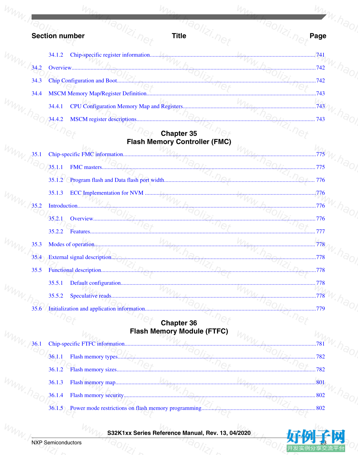
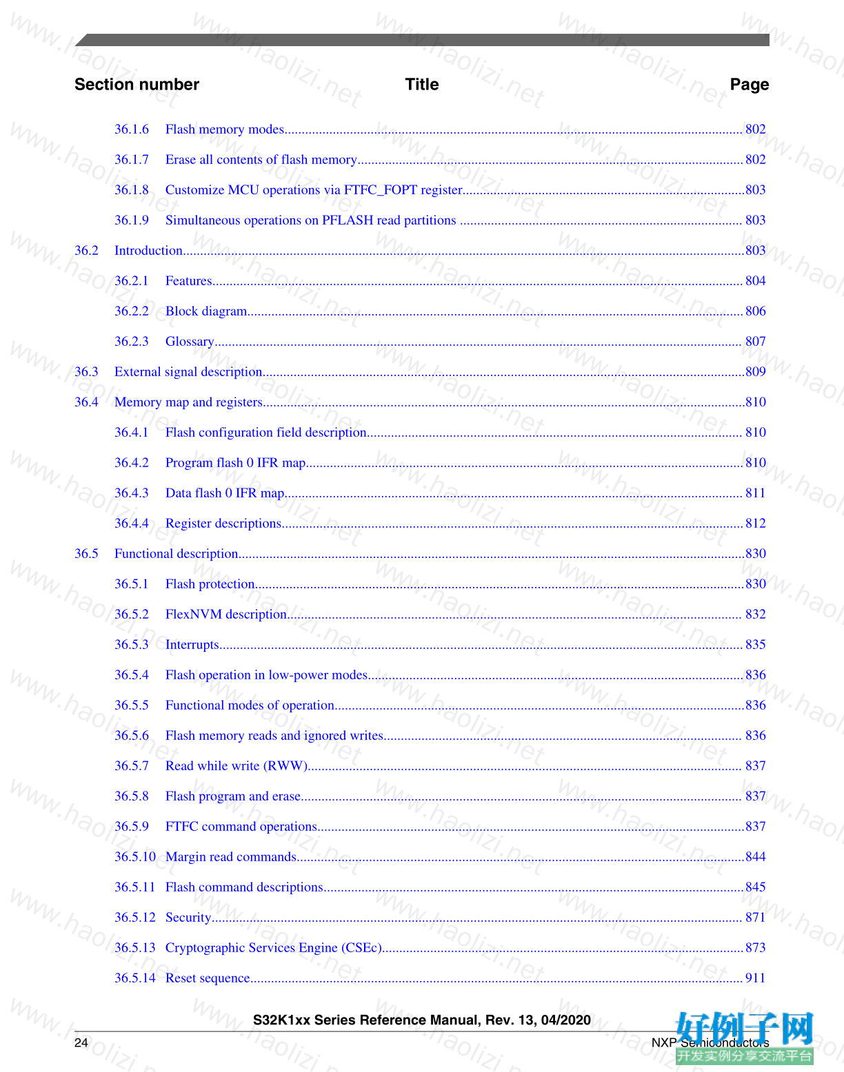
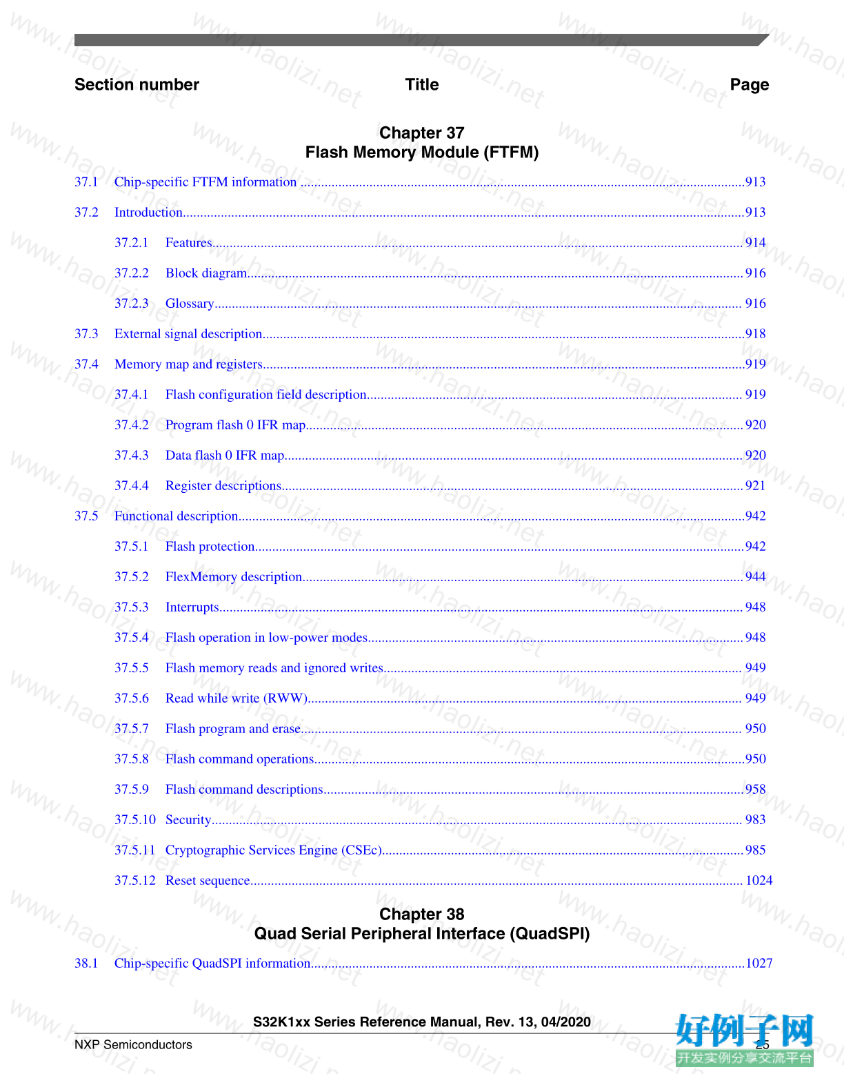
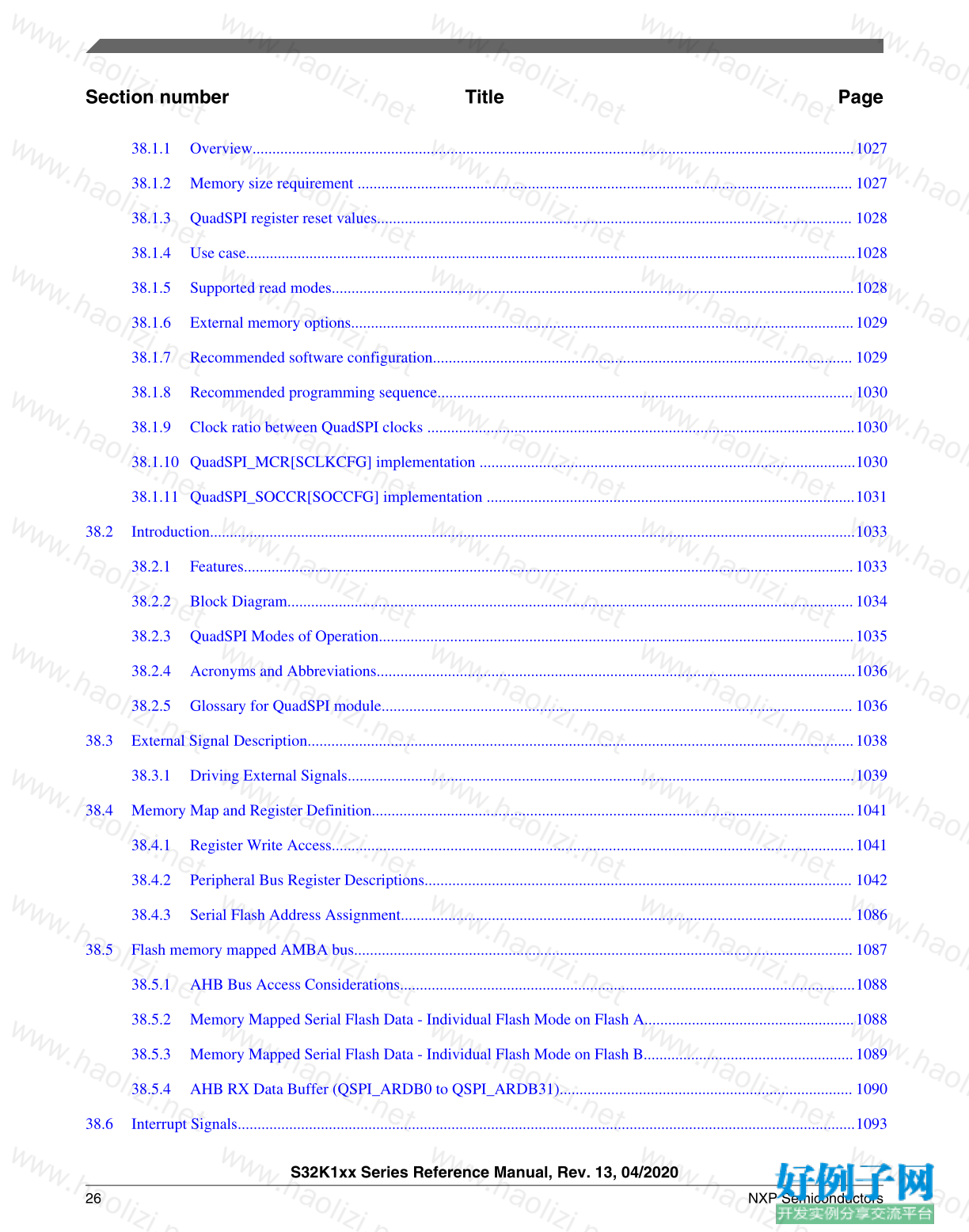



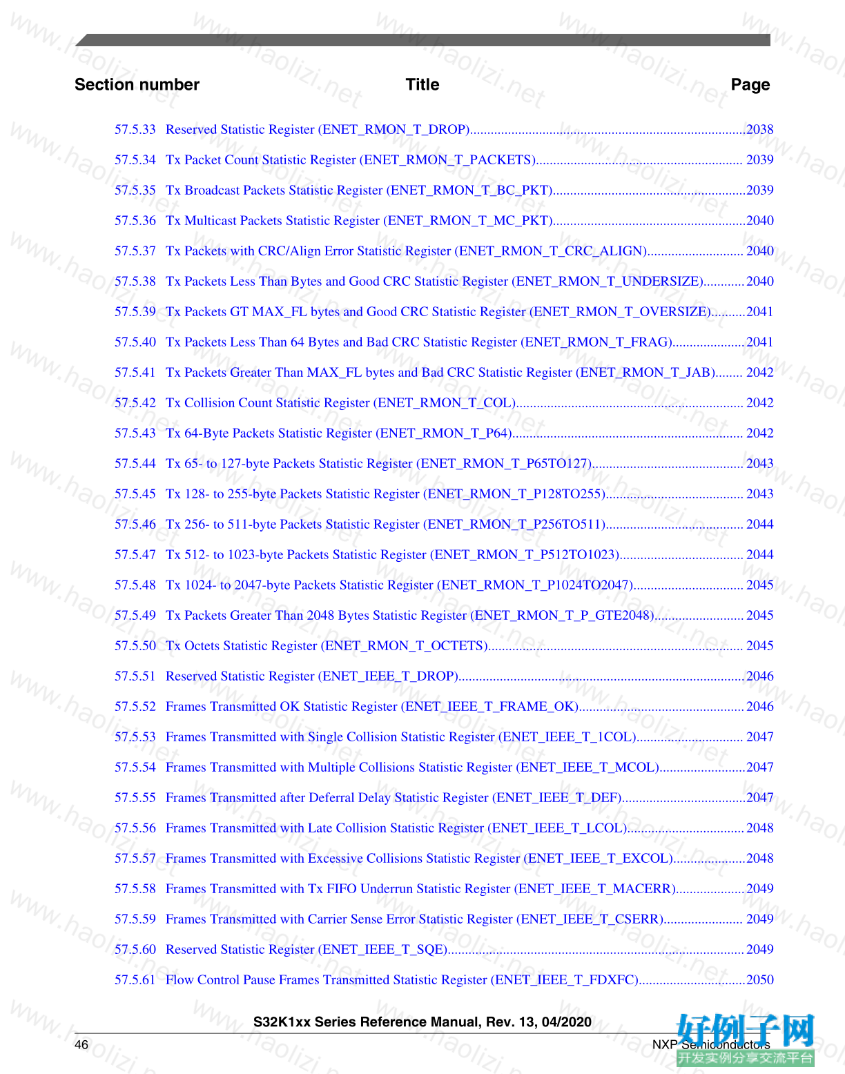
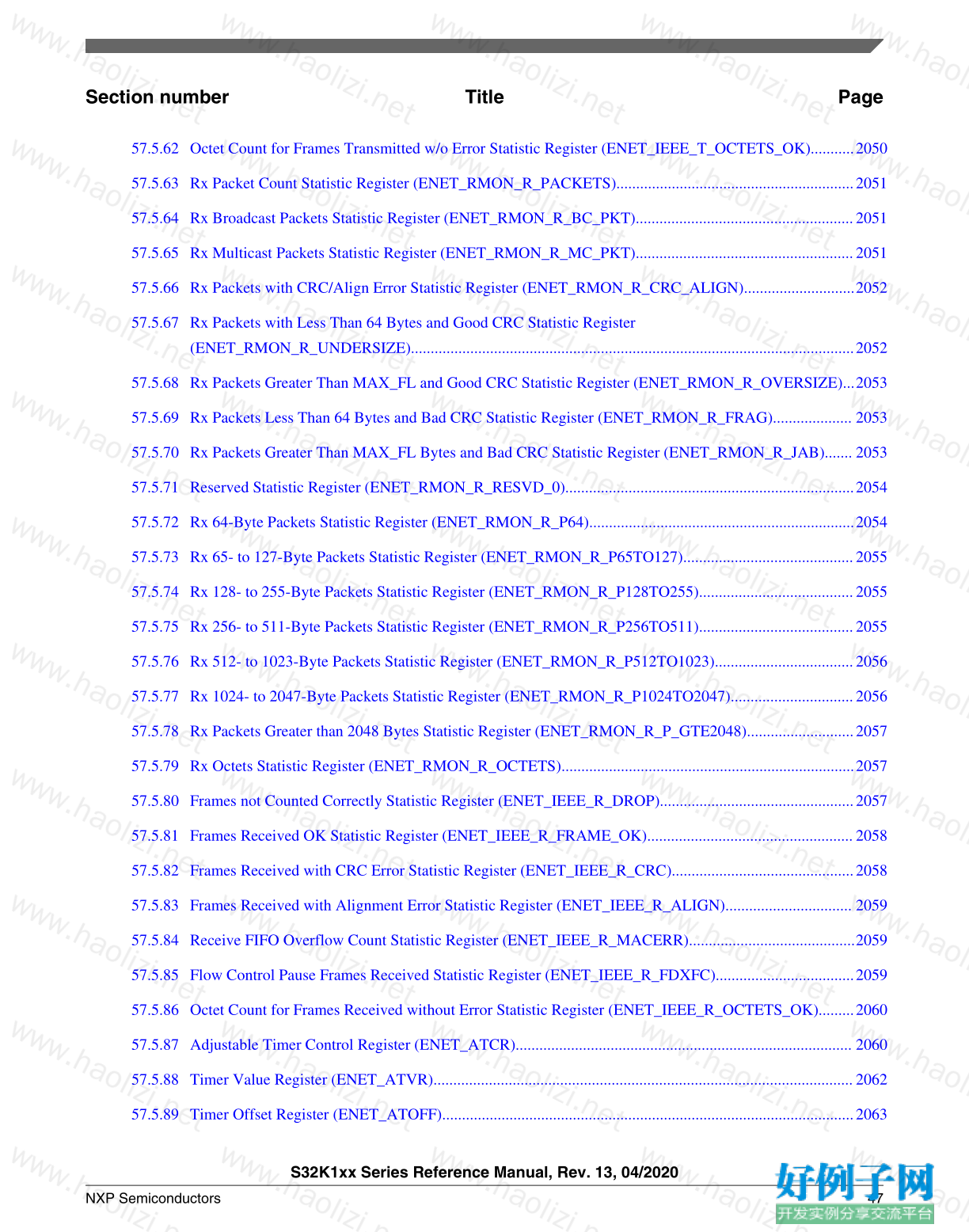
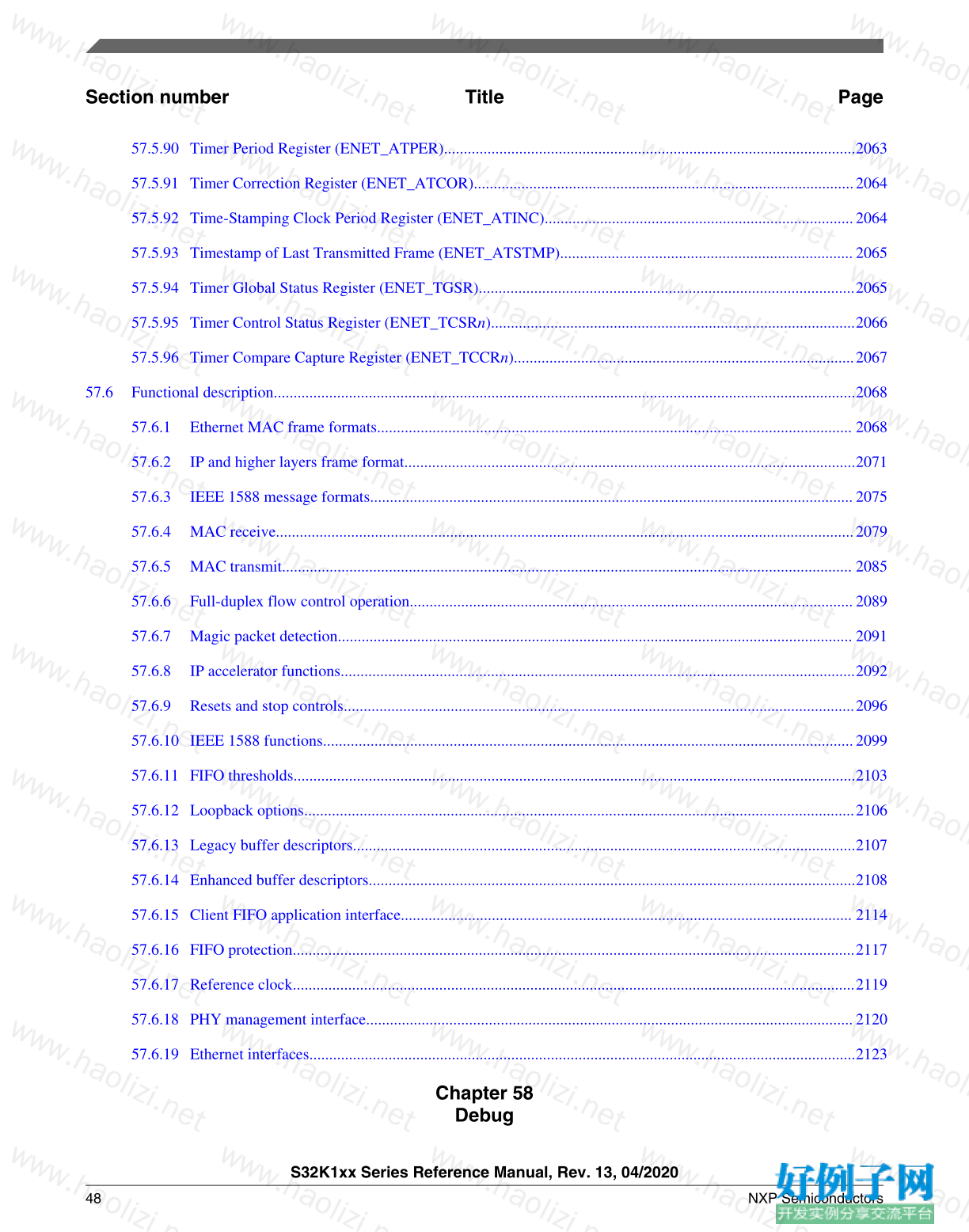
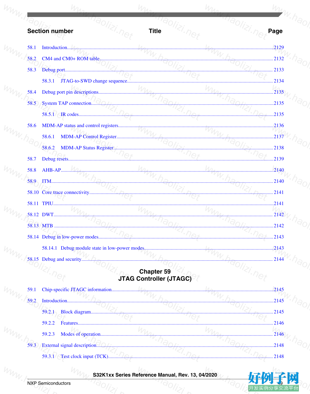
【核心代码】
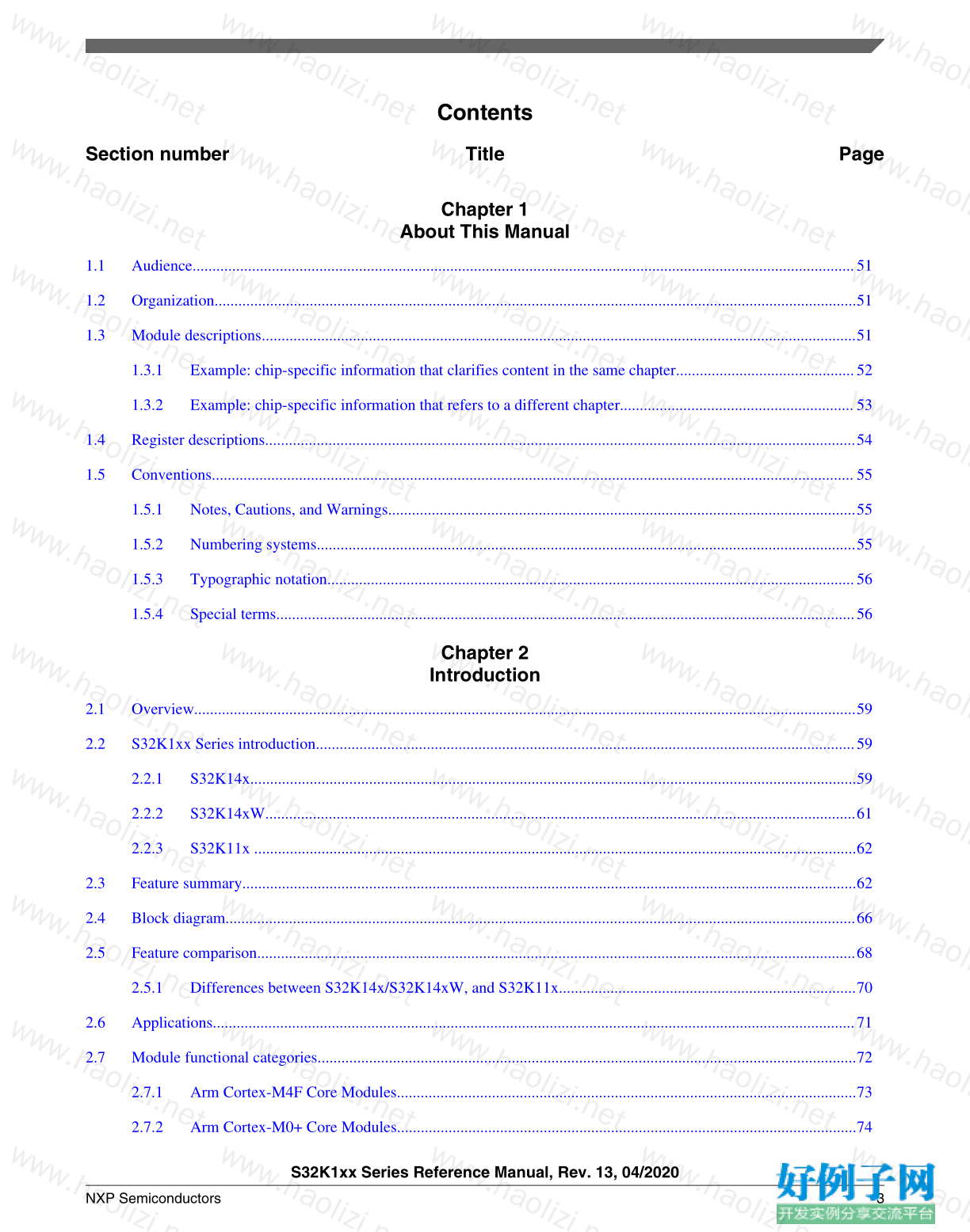
Contents
Section number Title Page
Chapter 1
About This Manual
1.1 Audience.......................................................................................................................................................................51
1.2 Organization..................................................................................................................................................................51
1.3 Module descriptions......................................................................................................................................................51
1.3.1 Example: chip-specific information that clarifies content in the same chapter.............................................52
1.3.2 Example: chip-specific information that refers to a different chapter...........................................................53
1.4 Register descriptions.....................................................................................................................................................54
1.5 Conventions..................................................................................................................................................................55
1.5.1 Notes, Cautions, and Warnings......................................................................................................................55
1.5.2 Numbering systems........................................................................................................................................55
1.5.3 Typographic notation.....................................................................................................................................56
1.5.4 Special terms..................................................................................................................................................56
Chapter 2
Introduction
2.1 Overview.......................................................................................................................................................................59
2.2 S32K1xx Series introduction........................................................................................................................................59
2.2.1 S32K14x.........................................................................................................................................................59
2.2.2 S32K14xW.....................................................................................................................................................61
2.2.3 S32K11x ........................................................................................................................................................62
2.3 Feature summary...........................................................................................................................................................62
2.4 Block diagram...............................................................................................................................................................66
2.5 Feature comparison.......................................................................................................................................................68
2.5.1 Differences between S32K14x/S32K14xW, and S32K11x...........................................................................70
2.6 Applications..................................................................................................................................................................71
2.7 Module functional categories........................................................................................................................................72
2.7.1 Arm Cortex-M4F Core Modules....................................................................................................................73
2.7.2 Arm Cortex-M0 Core Modules....................................................................................................................74
S32K1xx Series Reference Manual, Rev. 13, 04/2020
NXP Semiconductors 3
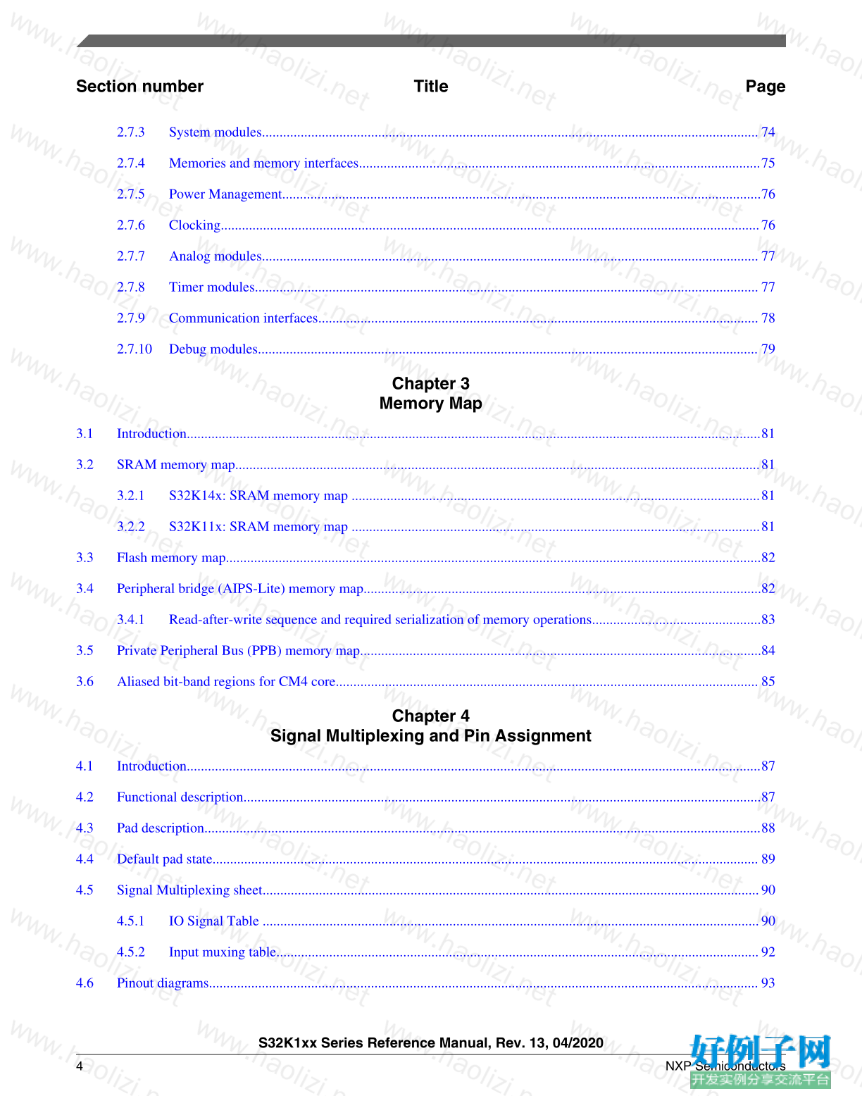
Section number Title Page
2.7.3 System modules............................................................................................................................................. 74
2.7.4 Memories and memory interfaces..................................................................................................................75
2.7.5 Power Management........................................................................................................................................76
2.7.6 Clocking.........................................................................................................................................................76
2.7.7 Analog modules............................................................................................................................................. 77
2.7.8 Timer modules............................................................................................................................................... 77
2.7.9 Communication interfaces............................................................................................................................. 78
2.7.10 Debug modules.............................................................................................................................................. 79
Chapter 3
Memory Map
3.1 Introduction...................................................................................................................................................................81
3.2 SRAM memory map.....................................................................................................................................................81
3.2.1 S32K14x: SRAM memory map ....................................................................................................................81
3.2.2 S32K11x: SRAM memory map ....................................................................................................................81
3.3 Flash memory map........................................................................................................................................................82
3.4 Peripheral bridge (AIPS-Lite) memory map.................................................................................................................82
3.4.1 Read-after-write sequence and required serialization of memory operations................................................83
3.5 Private Peripheral Bus (PPB) memory map..................................................................................................................84
3.6 Aliased bit-band regions for CM4 core........................................................................................................................ 85
Chapter 4
Signal Multiplexing and Pin Assignment
4.1 Introduction...................................................................................................................................................................87
4.2 Functional description...................................................................................................................................................87
4.3 Pad description..............................................................................................................................................................88
4.4 Default pad state........................................................................................................................................................... 89
4.5 Signal Multiplexing sheet.............................................................................................................................................90
4.5.1 IO Signal Table .............................................................................................................................................90
4.5.2 Input muxing table.........................................................................................................................................92
4.6 Pinout diagrams............................................................................................................................................................ 93
S32K1xx Series Reference Manual, Rev. 13, 04/2020
4 NXP Semiconductors
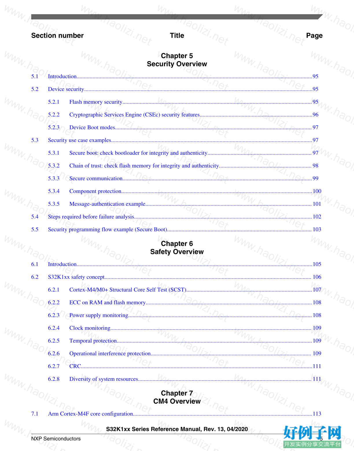
Section number Title Page
Chapter 5
Security Overview
5.1 Introduction...................................................................................................................................................................95
5.2 Device security..............................................................................................................................................................95
5.2.1 Flash memory security...................................................................................................................................95
5.2.2 Cryptographic Services Engine (CSEc) security features..............................................................................96
5.2.3 Device Boot modes........................................................................................................................................97
5.3 Security use case examples...........................................................................................................................................97
5.3.1 Secure boot: check bootloader for integrity and authenticity........................................................................97
5.3.2 Chain of trust: check flash memory for integrity and authenticity................................................................98
5.3.3 Secure communication...................................................................................................................................99
5.3.4 Component protection....................................................................................................................................100
5.3.5 Message-authentication example...................................................................................................................101
5.4 Steps required before failure analysis...........................................................................................................................102
5.5 Security programming flow example (Secure Boot)....................................................................................................103
Chapter 6
Safety Overview
6.1 Introduction...................................................................................................................................................................105
6.2 S32K1xx safety concept............................................................................................................................................... 106
6.2.1 Cortex-M4/M0 Structural Core Self Test (SCST).......................................................................................107
6.2.2 ECC on RAM and flash memory...................................................................................................................108
6.2.3 Power supply monitoring...............................................................................................................................108
6.2.4 Clock monitoring........................................................................................................................................... 109
6.2.5 Temporal protection.......................................................................................................................................109
6.2.6 Operational interference protection............................................................................................................... 109
6.2.7 CRC................................................................................................................................................................111
6.2.8 Diversity of system resources........................................................................................................................111
Chapter 7
CM4 Overview
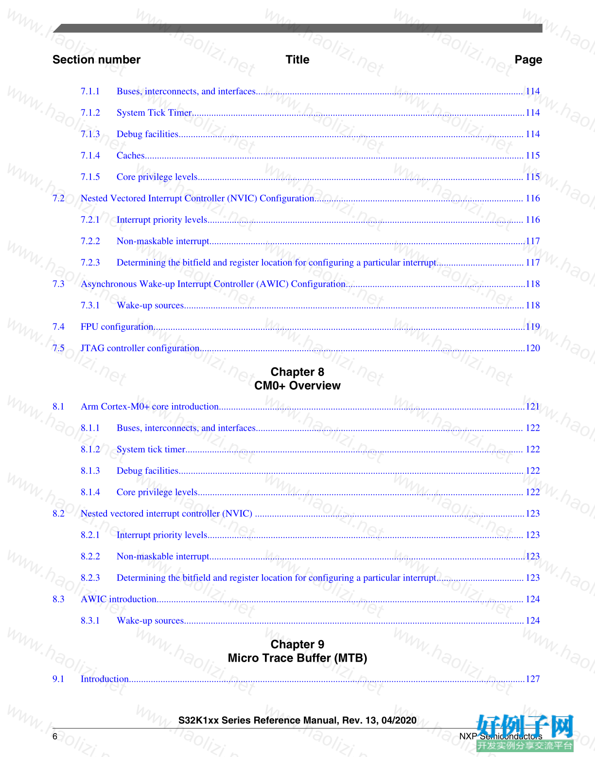
7.1 Arm Cortex-M4F core configuration............................................................................................................................113
S32K1xx Series Reference Manual, Rev. 13, 04/2020
NXP Semiconductors 5
Section number Title Page
7.1.1 Buses, interconnects, and interfaces.............................................................................................................. 114
7.1.2 System Tick Timer.........................................................................................................................................114
7.1.3 Debug facilities..............................................................................................................................................114
7.1.4 Caches............................................................................................................................................................115
7.1.5 Core privilege levels...................................................................................................................................... 115
7.2 Nested Vectored Interrupt Controller (NVIC) Configuration...................................................................................... 116
7.2.1 Interrupt priority levels.................................................................................................................................. 116
7.2.2 Non-maskable interrupt..................................................................................................................................117
7.2.3 Determining the bitfield and register location for configuring a particular interrupt....................................117
7.3 Asynchronous Wake-up Interrupt Controller (AWIC) Configuration..........................................................................118
7.3.1 Wake-up sources............................................................................................................................................118
7.4 FPU configuration.........................................................................................................................................................119
7.5 JTAG controller configuration......................................................................................................................................120
Chapter 8
CM0 Overview
8.1 Arm Cortex-M0 core introduction..............................................................................................................................121
8.1.1 Buses, interconnects, and interfaces.............................................................................................................. 122
8.1.2 System tick timer........................................................................................................................................... 122
8.1.3 Debug facilities..............................................................................................................................................122
8.1.4 Core privilege levels...................................................................................................................................... 122
8.2 Nested vectored interrupt controller (NVIC) ...............................................................................................................123
8.2.1 Interrupt priority levels.................................................................................................................................. 123
8.2.2 Non-maskable interrupt..................................................................................................................................123
8.2.3 Determining the bitfield and register location for configuring a particular interrupt....................................123
8.3 AWIC introduction.......................................................................................................................................................124
8.3.1 Wake-up sources............................................................................................................................................124
Chapter 9
Micro Trace Buffer (MTB)
9.1 Introduction...................................................................................................................................................................127
S32K1xx Series Reference Manual, Rev. 13, 04/2020
6 NXP Semiconductors
Section number Title Page
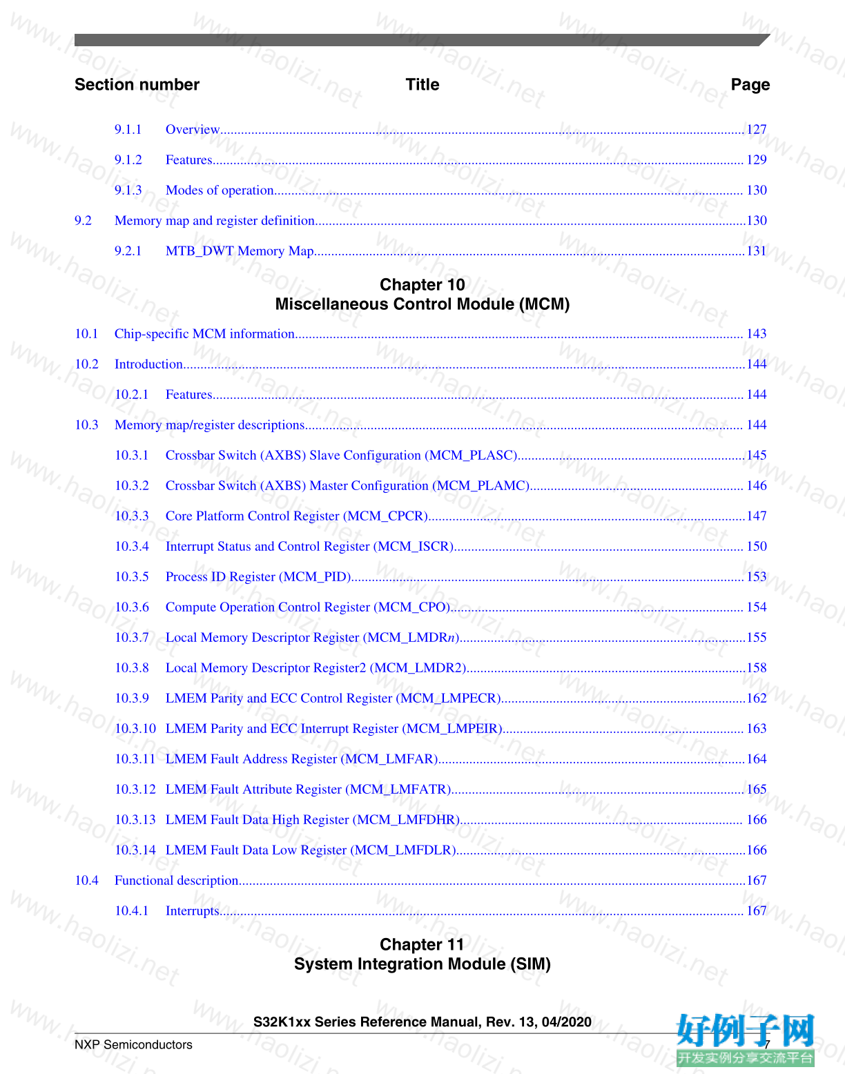
9.1.1 Overview........................................................................................................................................................127
9.1.2 Features..........................................................................................................................................................129
9.1.3 Modes of operation........................................................................................................................................ 130
9.2 Memory map and register definition.............................................................................................................................130
9.2.1 MTB_DWT Memory Map.............................................................................................................................131
Chapter 10
Miscellaneous Control Module (MCM)
10.1 Chip-specific MCM information..................................................................................................................................143
10.2 Introduction...................................................................................................................................................................144
10.2.1 Features..........................................................................................................................................................144
10.3 Memory map/register descriptions............................................................................................................................... 144
10.3.1 Crossbar Switch (AXBS) Slave Configuration (MCM_PLASC)..................................................................145
10.3.2 Crossbar Switch (AXBS) Master Configuration (MCM_PLAMC)..............................................................146
10.3.3 Core Platform Control Register (MCM_CPCR)............................................................................................147
10.3.4 Interrupt Status and Control Register (MCM_ISCR)....................................................................................150
10.3.5 Process ID Register (MCM_PID)..................................................................................................................153
10.3.6 Compute Operation Control Register (MCM_CPO).....................................................................................154
10.3.7 Local Memory Descriptor Register (MCM_LMDRn)...................................................................................155
10.3.8 Local Memory Descriptor Register2 (MCM_LMDR2).................................................................................158
10.3.9 LMEM Parity and ECC Control Register (MCM_LMPECR).......................................................................162
10.3.10 LMEM Parity and ECC Interrupt Register (MCM_LMPEIR)......................................................................163
10.3.11 LMEM Fault Address Register (MCM_LMFAR).........................................................................................164
10.3.12 LMEM Fault Attribute Register (MCM_LMFATR).....................................................................................165
10.3.13 LMEM Fault Data High Register (MCM_LMFDHR).................................................................................. 166
10.3.14 LMEM Fault Data Low Register (MCM_LMFDLR)....................................................................................166
10.4 Functional description...................................................................................................................................................167
10.4.1 Interrupts........................................................................................................................................................167
Chapter 11
System Integration Module (SIM)
S32K1xx Series Reference Manual, Rev. 13, 04/2020
NXP Semiconductors 7
Section number Title Page
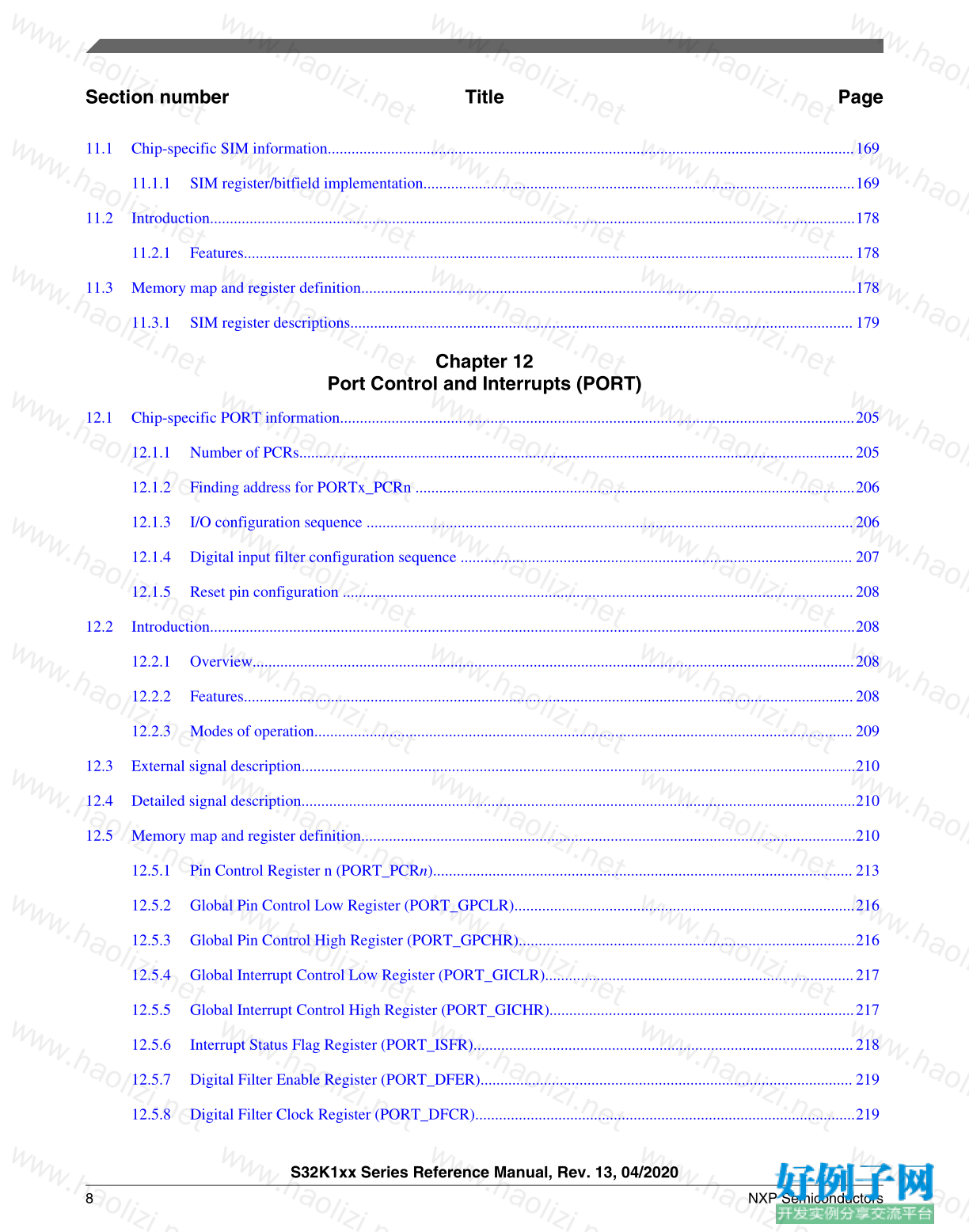
11.1 Chip-specific SIM information.....................................................................................................................................169
11.1.1 SIM register/bitfield implementation.............................................................................................................169
11.2 Introduction...................................................................................................................................................................178
11.2.1 Features..........................................................................................................................................................178
11.3 Memory map and register definition.............................................................................................................................178
11.3.1 SIM register descriptions...............................................................................................................................179
Chapter 12
Port Control and Interrupts (PORT)
12.1 Chip-specific PORT information..................................................................................................................................205
12.1.1 Number of PCRs............................................................................................................................................205
12.1.2 Finding address for PORTx_PCRn ...............................................................................................................206
12.1.3 I/O configuration sequence ...........................................................................................................................206
12.1.4 Digital input filter configuration sequence ................................................................................................... 207
12.1.5 Reset pin configuration .................................................................................................................................208
12.2 Introduction...................................................................................................................................................................208
12.2.1 Overview........................................................................................................................................................208
12.2.2 Features..........................................................................................................................................................208
12.2.3 Modes of operation........................................................................................................................................ 209
12.3 External signal description............................................................................................................................................210
12.4 Detailed signal description............................................................................................................................................210
12.5 Memory map and register definition.............................................................................................................................210
12.5.1 Pin Control Register n (PORT_PCRn).......................................................................................................... 213
12.5.2 Global Pin Control Low Register (PORT_GPCLR)......................................................................................216
12.5.3 Global Pin Control High Register (PORT_GPCHR).....................................................................................216
12.5.4 Global Interrupt Control Low Register (PORT_GICLR)..............................................................................217
12.5.5 Global Interrupt Control High Register (PORT_GICHR).............................................................................217
12.5.6 Interrupt Status Flag Register (PORT_ISFR)................................................................................................218
12.5.7 Digital Filter Enable Register (PORT_DFER).............................................................................................. 219
12.5.8 Digital Filter Clock Register (PORT_DFCR)................................................................................................219
S32K1xx Series Reference Manual, Rev. 13, 04/2020
8 NXP Semiconductors
Section number Title Page
12.5.9 Digital Filter Width Register (PORT_DFWR)..............................................................................................220
12.6 Functional description...................................................................................................................................................220
12.6.1 Pin control......................................................................................................................................................220
12.6.2 Global pin control.......................................................................................................................................... 221
12.6.3 Global interrupt control..................................................................................................................................222
12.6.4 External interrupts..........................................................................................................................................222
12.6.5 Digital filter....................................................................................................................................................223
Chapter 13
General-Purpose Input/Output (GPIO)
13.1 Chip-specific GPIO information...................................................................................................................................225
13.1.1 Instantiation information................................................................................................................................225
13.1.2 GPIO ports memory map...............................................................................................................................225
13.1.3 GPIO register reset values .............................................................................................................................226
13.2 Introduction...................................................................................................................................................................226
13.2.1 Features..........................................................................................................................................................227
13.2.2 Modes of operation........................................................................................................................................ 227
13.2.3 GPIO signal descriptions............................................................................................................................... 227
13.3 Memory map and register definition.............................................................................................................................228
13.3.1 GPIO register descriptions.............................................................................................................................228
13.4 Functional description...................................................................................................................................................236
13.4.1 General-purpose input....................................................................................................................................236
13.4.2 General-purpose output..................................................................................................................................236
Chapter 14
Crossbar Switch Lite (AXBS-Lite)
14.1 Chip-specific AXBS-Lite information..........................................................................................................................239
14.1.1 Crossbar Switch master assignments.............................................................................................................239
14.1.2 Crossbar Switch slave assignments................................................................................................................239
14.2 Introduction...................................................................................................................................................................240
14.2.1 Features..........................................................................................................................................................240
S32K1xx Series Reference Manual, Rev. 13, 04/2020
NXP Semiconductors 9
Section number Title Page
14.3 Functional Description..................................................................................................................................................241
14.3.1 General operation...........................................................................................................................................241
14.3.2 Arbitration......................................................................................................................................................241
14.4 Initialization/application information...........................................................................................................................243
Chapter 15
Memory Protection Unit (MPU)
15.1 Chip-specific MPU information................................................................................................................................... 245
15.1.1 MPU Slave Port Assignments........................................................................................................................245
15.1.2 MPU Logical Bus Master Assignments.........................................................................................................246
15.1.3 Current PID....................................................................................................................................................246
15.1.4 Region descriptors and slave port configuration............................................................................................246
15.2 Introduction...................................................................................................................................................................247
15.3 Overview.......................................................................................................................................................................247
15.3.1 Block diagram................................................................................................................................................247
15.3.2 Features..........................................................................................................................................................248
15.4 MPU register descriptions.............................................................................................................................................249
15.4.1 MPU memory map.........................................................................................................................................249
15.4.2 Control/Error Status Register (CESR)...........................................................................................................252
15.4.3 Error Address Register, slave port n (EAR0 - EAR4)...................................................................................254
15.4.4 Error Detail Register, slave port n (EDR0 - EDR4)...................................................................................... 255
15.4.5 Region Descriptor n, Word 0 (RGD0_WORD0 - RGD15_WORD0)...........................................................257
15.4.6 Region Descriptor 0, Word 1 (RGD0_WORD1)...........................................................................................258
15.4.7 Region Descriptor 0, Word 2 (RGD0_WORD2)...........................................................................................259
15.4.8 Region Descriptor 0, Word 3 (RGD0_WORD3)...........................................................................................262
15.4.9 Region Descriptor n, Word 1 (RGD1_WORD1 - RGD15_WORD1)...........................................................263
15.4.10 Region Descriptor n, Word 2 (RGD1_WORD2 - RGD15_WORD2)...........................................................264
15.4.11 Region Descriptor n, Word 3 (RGD1_WORD3 - RGD15_WORD3)...........................................................267
15.4.12 Region Descriptor Alternate Access Control 0 (RGDAAC0).......................................................................269
15.4.13 Region Descriptor Alternate Access Control n (RGDAAC1 - RGDAAC15)...............................................272
S32K1xx Series Reference Manual, Rev. 13, 04/2020
10 NXP Semiconductors
Section number Title Page
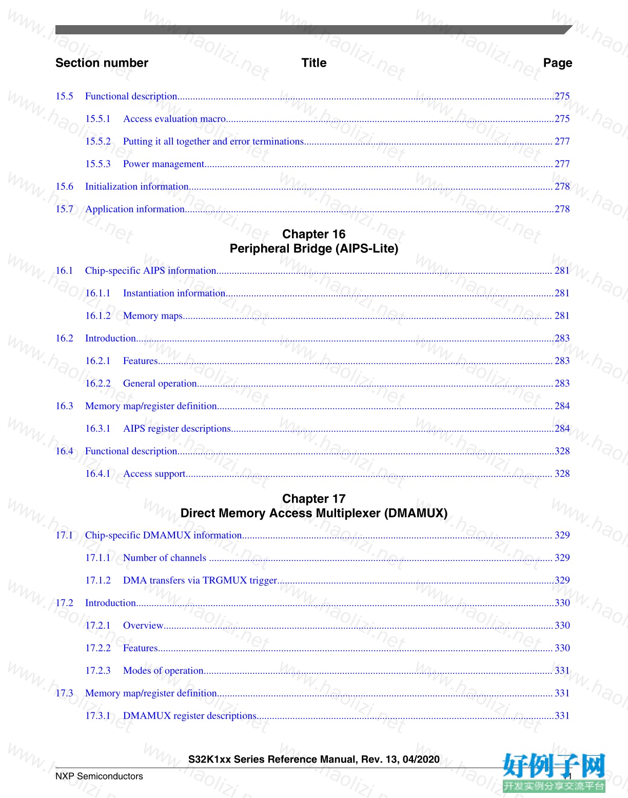
15.5 Functional description...................................................................................................................................................275
15.5.1 Access evaluation macro................................................................................................................................275
15.5.2 Putting it all together and error terminations.................................................................................................277
15.5.3 Power management........................................................................................................................................277
15.6 Initialization information..............................................................................................................................................278
15.7 Application information................................................................................................................................................278
Chapter 16
Peripheral Bridge (AIPS-Lite)
16.1 Chip-specific AIPS information................................................................................................................................... 281
16.1.1 Instantiation information................................................................................................................................281
16.1.2 Memory maps................................................................................................................................................ 281
16.2 Introduction...................................................................................................................................................................283
16.2.1 Features..........................................................................................................................................................283
16.2.2 General operation...........................................................................................................................................283
16.3 Memory map/register definition...................................................................................................................................284
16.3.1 AIPS register descriptions..............................................................................................................................284
16.4 Functional description...................................................................................................................................................328
16.4.1 Access support............................................................................................................................................... 328
Chapter 17
Direct Memory Access Multiplexer (DMAMUX)
17.1 Chip-specific DMAMUX information......................................................................................................................... 329
17.1.1 Number of channels ......................................................................................................................................329
17.1.2 DMA transfers via TRGMUX trigger............................................................................................................329
17.2 Introduction...................................................................................................................................................................330
17.2.1 Overview........................................................................................................................................................330
17.2.2 Features..........................................................................................................................................................330
17.2.3 Modes of operation........................................................................................................................................ 331
17.3 Memory map/register definition...................................................................................................................................331
17.3.1 DMAMUX register descriptions....................................................................................................................331
S32K1xx Series Reference Manual, Rev. 13, 04/2020
NXP Semiconductors 11
Section number Title Page
17.4 Functional description...................................................................................................................................................333
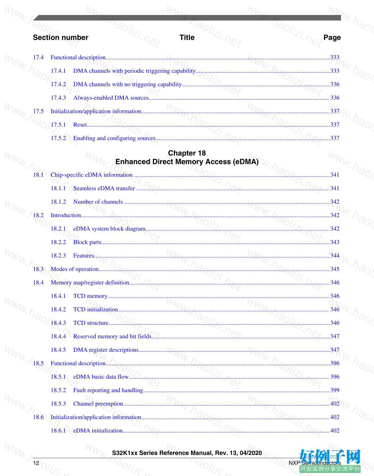
17.4.1 DMA channels with periodic triggering capability........................................................................................333
17.4.2 DMA channels with no triggering capability.................................................................................................336
17.4.3 Always-enabled DMA sources...................................................................................................................... 336
17.5 Initialization/application information...........................................................................................................................337
17.5.1 Reset...............................................................................................................................................................337
17.5.2 Enabling and configuring sources..................................................................................................................337
Chapter 18
Enhanced Direct Memory Access (eDMA)
18.1 Chip-specific eDMA information ................................................................................................................................341
18.1.1 Seamless eDMA transfer .............................................................................................................................. 341
18.1.2 Number of channels ......................................................................................................................................342
18.2 Introduction...................................................................................................................................................................342
18.2.1 eDMA system block diagram........................................................................................................................ 342
18.2.2 Block parts..................................................................................................................................................... 343
18.2.3 Features..........................................................................................................................................................344
18.3 Modes of operation.......................................................................................................................................................345
18.4 Memory map/register definition...................................................................................................................................346
18.4.1 TCD memory................................................................................................................................................. 346
18.4.2 TCD initialization.......................................................................................................................................... 346
18.4.3 TCD structure.................................................................................................................................................346
18.4.4 Reserved memory and bit fields.....................................................................................................................347
18.4.5 DMA register descriptions.............................................................................................................................347
18.5 Functional description...................................................................................................................................................396
18.5.1 eDMA basic data flow................................................................................................................................... 396
18.5.2 Fault reporting and handling..........................................................................................................................399
18.5.3 Channel preemption.......................................................................................................................................402
18.6 Initialization/application information...........................................................................................................................402
18.6.1 eDMA initialization....................................................................................................................................... 402
S32K1xx Series Reference Manual, Rev. 13, 04/2020
12 NXP Semiconductors
Section number Title Page
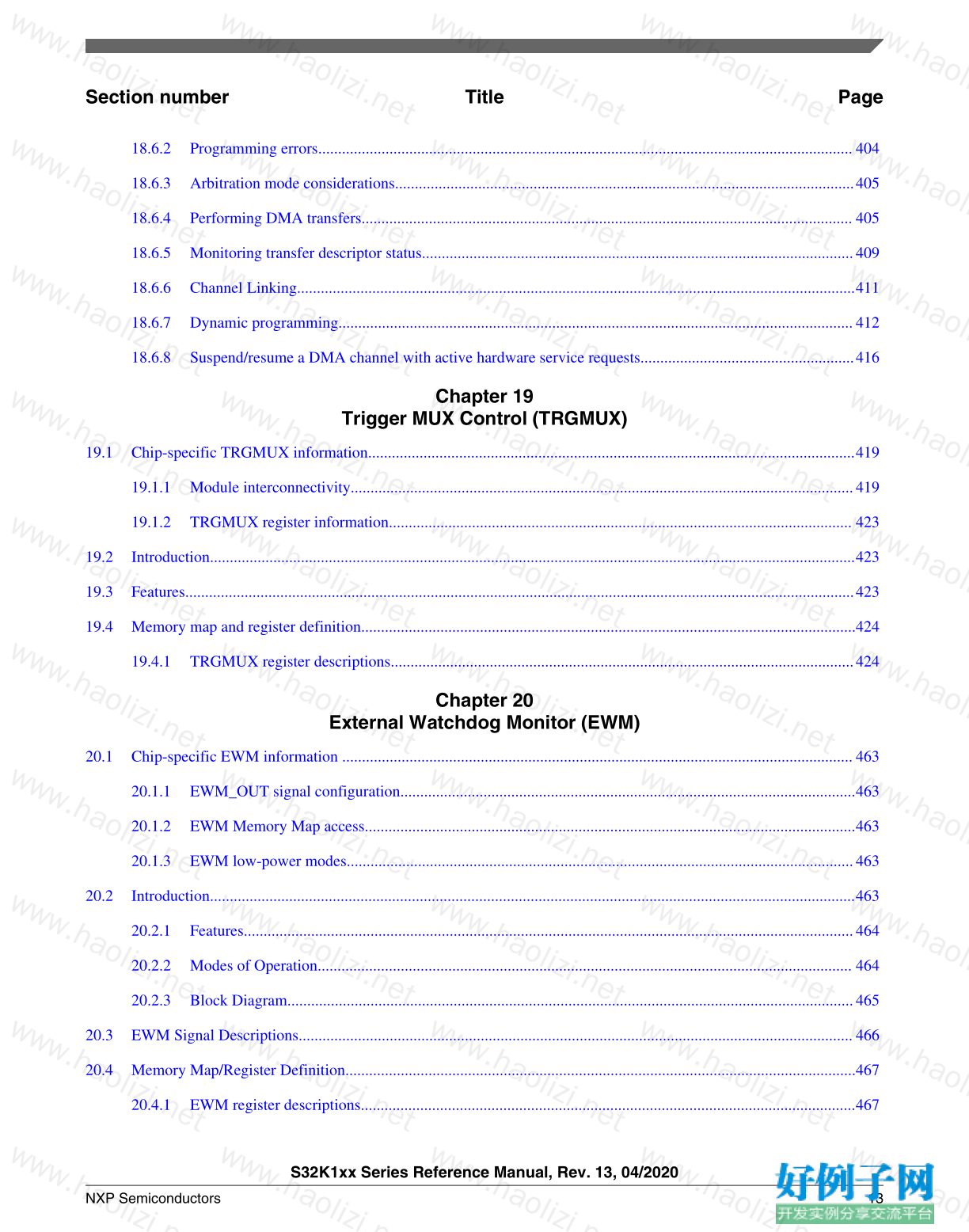
18.6.2 Programming errors....................................................................................................................................... 404
18.6.3 Arbitration mode considerations....................................................................................................................405
18.6.4 Performing DMA transfers............................................................................................................................ 405
18.6.5 Monitoring transfer descriptor status.............................................................................................................409
18.6.6 Channel Linking.............................................................................................................................................411
18.6.7 Dynamic programming..................................................................................................................................412
18.6.8 Suspend/resume a DMA channel with active hardware service requests......................................................416
Chapter 19
Trigger MUX Control (TRGMUX)
19.1 Chip-specific TRGMUX information...........................................................................................................................419
19.1.1 Module interconnectivity...............................................................................................................................419
19.1.2 TRGMUX register information..................................................................................................................... 423
19.2 Introduction...................................................................................................................................................................423
19.3 Features.........................................................................................................................................................................423
19.4 Memory map and register definition.............................................................................................................................424
19.4.1 TRGMUX register descriptions.....................................................................................................................424
Chapter 20
External Watchdog Monitor (EWM)
20.1 Chip-specific EWM information .................................................................................................................................463
20.1.1 EWM_OUT signal configuration...................................................................................................................463
20.1.2 EWM Memory Map access............................................................................................................................463
20.1.3 EWM low-power modes................................................................................................................................463
20.2 Introduction...................................................................................................................................................................463
20.2.1 Features..........................................................................................................................................................464
20.2.2 Modes of Operation....................................................................................................................................... 464
20.2.3 Block Diagram...............................................................................................................................................465
20.3 EWM Signal Descriptions............................................................................................................................................466
20.4 Memory Map/Register Definition.................................................................................................................................467
20.4.1 EWM register descriptions.............................................................................................................................467
S32K1xx Series Reference Manual, Rev. 13, 04/2020
NXP Semiconductors 13
Section number Title Page
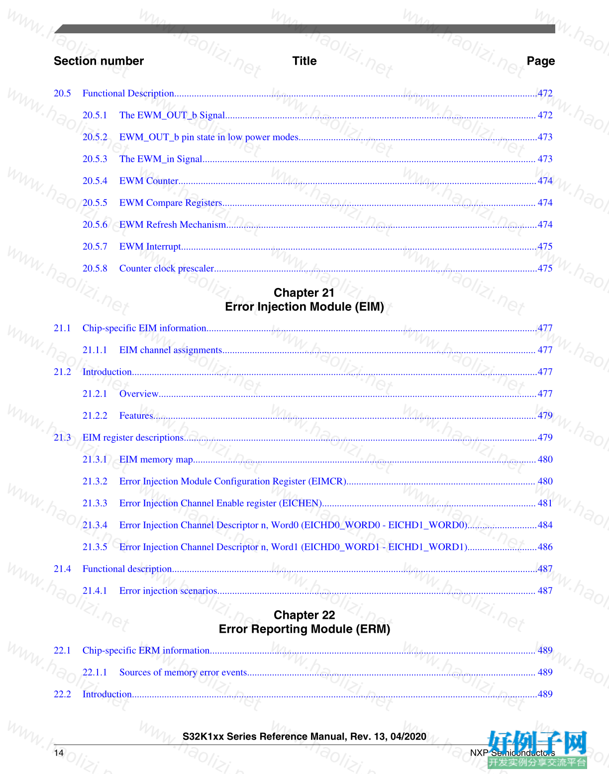
20.5 Functional Description..................................................................................................................................................472
20.5.1 The EWM_OUT_b Signal.............................................................................................................................472
20.5.2 EWM_OUT_b pin state in low power modes................................................................................................473
20.5.3 The EWM_in Signal...................................................................................................................................... 473
20.5.4 EWM Counter................................................................................................................................................474
20.5.5 EWM Compare Registers.............................................................................................................................. 474
20.5.6 EWM Refresh Mechanism.............................................................................................................................474
20.5.7 EWM Interrupt...............................................................................................................................................475
20.5.8 Counter clock prescaler..................................................................................................................................475
Chapter 21
Error Injection Module (EIM)
21.1 Chip-specific EIM information.....................................................................................................................................477
21.1.1 EIM channel assignments.............................................................................................................................. 477
21.2 Introduction...................................................................................................................................................................477
21.2.1 Overview........................................................................................................................................................477
21.2.2 Features..........................................................................................................................................................479
21.3 EIM register descriptions..............................................................................................................................................479
21.3.1 EIM memory map..........................................................................................................................................480
21.3.2 Error Injection Module Configuration Register (EIMCR)............................................................................ 480
21.3.3 Error Injection Channel Enable register (EICHEN)......................................................................................481
21.3.4 Error Injection Channel Descriptor n, Word0 (EICHD0_WORD0 - EICHD1_WORD0)............................484
21.3.5 Error Injection Channel Descriptor n, Word1 (EICHD0_WORD1 - EICHD1_WORD1)............................486
21.4 Functional description...................................................................................................................................................487
21.4.1 Error injection scenarios................................................................................................................................ 487
Chapter 22
Error Reporting Module (ERM)
22.1 Chip-specific ERM information................................................................................................................................... 489
22.1.1 Sources of memory error events.................................................................................................................... 489
22.2 Introduction...................................................................................................................................................................489
S32K1xx Series Reference Manual, Rev. 13, 04/2020
14 NXP Semiconductors
Section number Title Page
22.2.1 Overview........................................................................................................................................................489
22.2.2 Features..........................................................................................................................................................490
22.3 ERM register descriptions.............................................................................................................................................490
22.3.1 ERM memory map.........................................................................................................................................490
22.3.2 ERM Configuration Register 0 (CR0)...........................................................................................................491
22.3.3 ERM Status Register 0 (SR0)........................................................................................................................ 493
22.3.4 ERM Memory n Error Address Register (EAR0 - EAR1)............................................................................ 495
22.4 Functional description...................................................................................................................................................496
22.4.1 Single-bit correction events........................................................................................................................... 496
22.4.2 Non-correctable error events..........................................................................................................................497
22.5 Initialization..................................................................................................................................................................498
Chapter 23
Watchdog timer (WDOG)
23.1 Chip-specific WDOG information................................................................................................................................499
23.1.1 WDOG clocks................................................................................................................................................499
23.1.2 WDOG low-power modes............................................................................................................................. 499
23.1.3 Default watchdog timeout .............................................................................................................................500
23.1.4 Watchdog Timeout Reaction......................................................................................................................... 500
23.2 Introduction...................................................................................................................................................................501
23.2.1 Features..........................................................................................................................................................501
23.2.2 Block diagram................................................................................................................................................502
23.3 Memory map and register definition.............................................................................................................................502
23.3.1 WDOG register descriptions..........................................................................................................................502
23.4 Functional description...................................................................................................................................................509
23.4.1 Clock source...................................................................................................................................................509
23.4.2 Watchdog refresh mechanism........................................................................................................................510
23.4.3 Configuring the Watchdog.............................................................................................................................511
23.4.4 Using interrupts to delay resets......................................................................................................................512
23.4.5 Backup reset...................................................................................................................................................513
S32K1xx Series Reference Manual, Rev. 13, 04/2020
NXP Semiconductors 15
Section number Title Page
23.4.6 Functionality in debug and low-power modes...............................................................................................513
23.4.7 Fast testing of the watchdog...........................................................................................................................514
23.5 Application Information................................................................................................................................................515
23.5.1 Disable Watchdog..........................................................................................................................................515
23.5.2 Disable Watchdog after Reset........................................................................................................................516
23.5.3 Configure Watchdog......................................................................................................................................516
23.5.4 Refreshing the Watchdog...............................................................................................................................517
Chapter 24
Cyclic Redundancy Check (CRC)
24.1 Chip-specific CRC information....................................................................................................................................519
24.2 Introduction...................................................................................................................................................................519
24.2.1 Features..........................................................................................................................................................519
24.2.2 Block diagram................................................................................................................................................520
24.2.3 Modes of operation........................................................................................................................................ 520
24.3 Memory map and register descriptions.........................................................................................................................520
24.3.1 CRC register descriptions.............................................................................................................................. 520
24.4 Functional description...................................................................................................................................................525
24.4.1 CRC initialization/reinitialization..................................................................................................................525
24.4.2 CRC calculations............................................................................................................................................525
24.4.3 Transpose feature...........................................................................................................................................526
24.4.4 CRC result complement.................................................................................................................................528
Chapter 25
Reset and Boot
25.1 Introduction...................................................................................................................................................................529
25.2 Reset..............................................................................................................................................................................529
25.2.1 Power-on reset (POR)....................................................................................................................................530
25.2.2 System reset sources...................................................................................................................................... 530
25.2.3 MCU Resets...................................................................................................................................................534
25.2.4 Reset pin ........................................................................................................................................................534
S32K1xx Series Reference Manual, Rev. 13, 04/2020
16 NXP Semiconductors
Section number Title Page
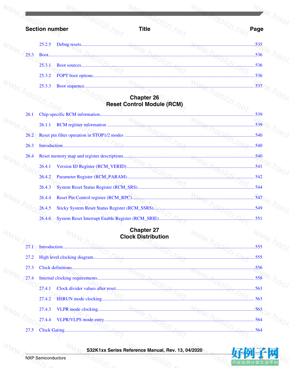
25.2.5 Debug resets...................................................................................................................................................535
25.3 Boot...............................................................................................................................................................................536
25.3.1 Boot sources...................................................................................................................................................536
25.3.2 FOPT boot options.........................................................................................................................................536
25.3.3 Boot sequence................................................................................................................................................537
Chapter 26
Reset Control Module (RCM)
26.1 Chip-specific RCM information...................................................................................................................................539
26.1.1 RCM register information .............................................................................................................................539
26.2 Reset pin filter operation in STOP1/2 modes ..............................................................................................................540
26.3 Introduction...................................................................................................................................................................540
26.4 Reset memory map and register descriptions...............................................................................................................540
26.4.1 Version ID Register (RCM_VERID).............................................................................................................541
26.4.2 Parameter Register (RCM_PARAM)............................................................................................................ 542
26.4.3 System Reset Status Register (RCM_SRS)...................................................................................................544
26.4.4 Reset Pin Control register (RCM_RPC)........................................................................................................547
26.4.5 Sticky System Reset Status Register (RCM_SSRS)......................................................................................549
26.4.6 System Reset Interrupt Enable Register (RCM_SRIE)................................................................................. 551
Chapter 27
Clock Distribution
27.1 Introduction...................................................................................................................................................................555
27.2 High level clocking diagram.........................................................................................................................................555
27.3 Clock definitions...........................................................................................................................................................556
27.4 Internal clocking requirements..................................................................................................................................... 558
27.4.1 Clock divider values after reset......................................................................................................................563
27.4.2 HSRUN mode clocking................................................................................................................................. 563
27.4.3 VLPR mode clocking.....................................................................................................................................563
27.4.4 VLPR/VLPS mode entry............................................................................................................................... 564
27.5 Clock Gating.................................................................................................................................................................564
S32K1xx Series Reference Manual, Rev. 13, 04/2020
NXP Semiconductors 17
Section number Title Page
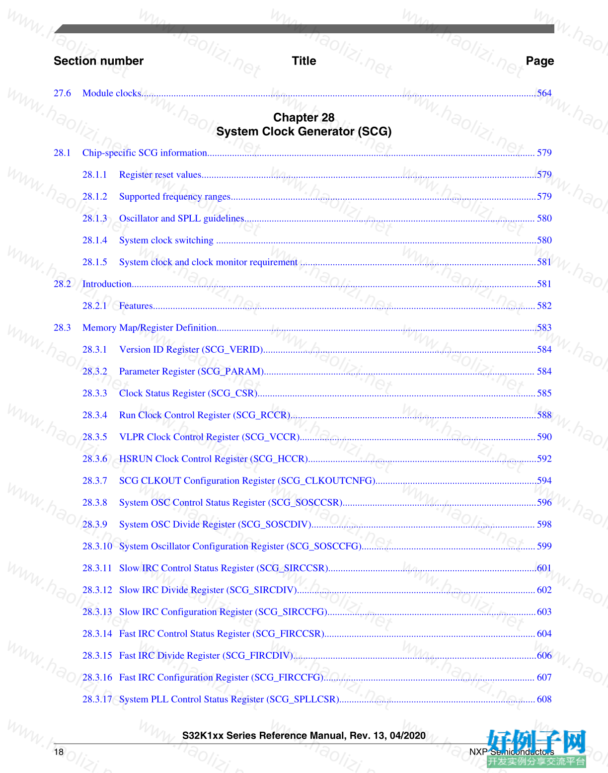
27.6 Module clocks...............................................................................................................................................................564
Chapter 28
System Clock Generator (SCG)
28.1 Chip-specific SCG information....................................................................................................................................579
28.1.1 Register reset values.......................................................................................................................................579
28.1.2 Supported frequency ranges...........................................................................................................................579
28.1.3 Oscillator and SPLL guidelines..................................................................................................................... 580
28.1.4 System clock switching .................................................................................................................................580
28.1.5 System clock and clock monitor requirement ...............................................................................................581
28.2 Introduction...................................................................................................................................................................581
28.2.1 Features..........................................................................................................................................................582
28.3 Memory Map/Register Definition.................................................................................................................................583
28.3.1 Version ID Register (SCG_VERID)..............................................................................................................584
28.3.2 Parameter Register (SCG_PARAM)............................................................................................................. 584
28.3.3 Clock Status Register (SCG_CSR)................................................................................................................585
28.3.4 Run Clock Control Register (SCG_RCCR)...................................................................................................588
28.3.5 VLPR Clock Control Register (SCG_VCCR)...............................................................................................590
28.3.6 HSRUN Clock Control Register (SCG_HCCR)............................................................................................592
28.3.7 SCG CLKOUT Configuration Register (SCG_CLKOUTCNFG).................................................................594
28.3.8 System OSC Control Status Register (SCG_SOSCCSR)..............................................................................596
28.3.9 System OSC Divide Register (SCG_SOSCDIV).......................................................................................... 598
28.3.10 System Oscillator Configuration Register (SCG_SOSCCFG)......................................................................599
28.3.11 Slow IRC Control Status Register (SCG_SIRCCSR)....................................................................................601
28.3.12 Slow IRC Divide Register (SCG_SIRCDIV)................................................................................................602
28.3.13 Slow IRC Configuration Register (SCG_SIRCCFG)....................................................................................603
28.3.14 Fast IRC Control Status Register (SCG_FIRCCSR).....................................................................................604
28.3.15 Fast IRC Divide Register (SCG_FIRCDIV)..................................................................................................606
28.3.16 Fast IRC Configuration Register (SCG_FIRCCFG)..................................................................................... 607
28.3.17 System PLL Control Status Register (SCG_SPLLCSR)...............................................................................608
S32K1xx Series Reference Manual, Rev. 13, 04/2020
18 NXP Semiconductors
Section number Title Page
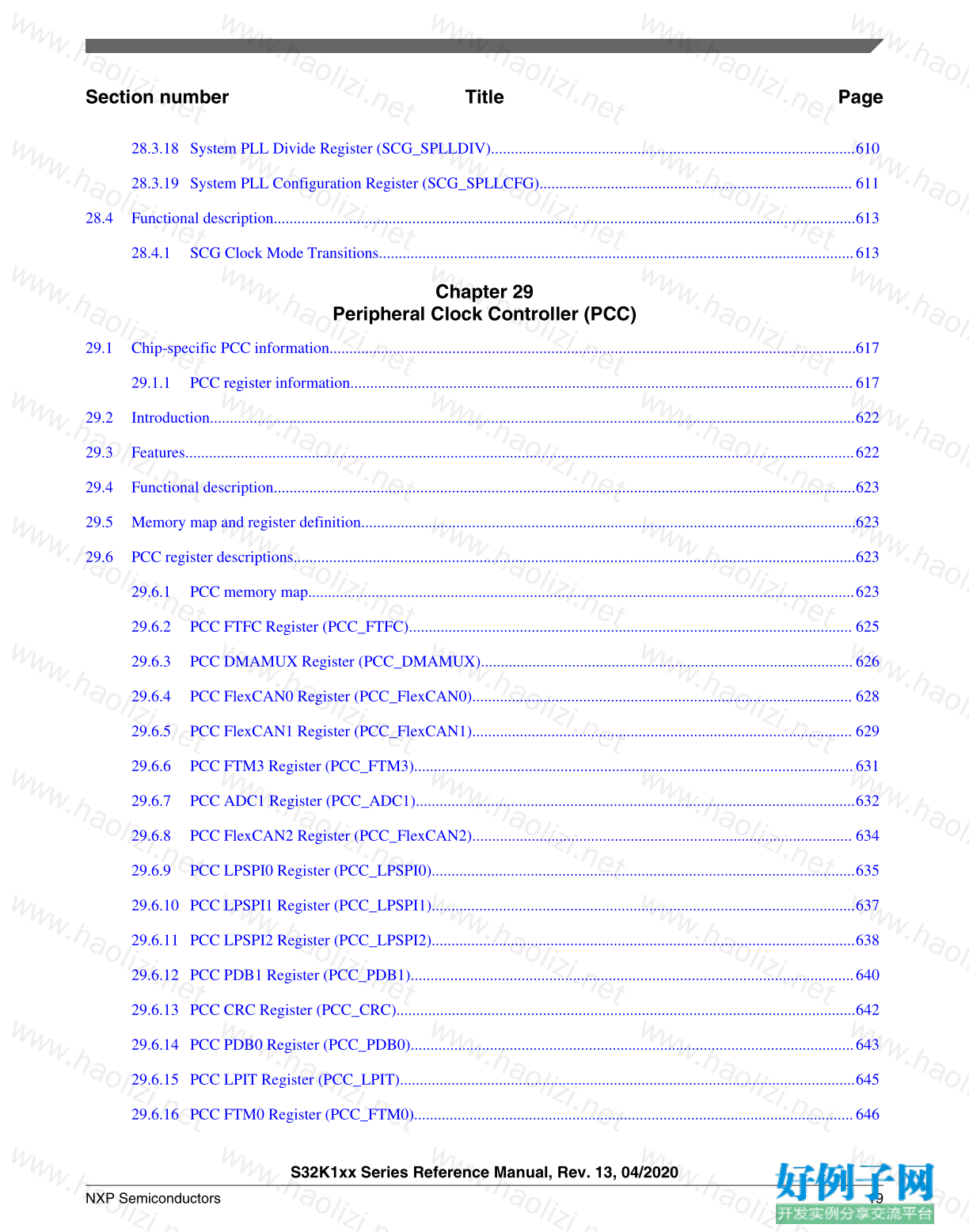
28.3.18 System PLL Divide Register (SCG_SPLLDIV)............................................................................................610
28.3.19 System PLL Configuration Register (SCG_SPLLCFG)............................................................................... 611
28.4 Functional description...................................................................................................................................................613
28.4.1 SCG Clock Mode Transitions........................................................................................................................613
Chapter 29
Peripheral Clock Controller (PCC)
29.1 Chip-specific PCC information.....................................................................................................................................617
29.1.1 PCC register information...............................................................................................................................617
29.2 Introduction...................................................................................................................................................................622
29.3 Features.........................................................................................................................................................................622
29.4 Functional description...................................................................................................................................................623
29.5 Memory map and register definition.............................................................................................................................623
29.6 PCC register descriptions..............................................................................................................................................623
29.6.1 PCC memory map..........................................................................................................................................623
29.6.2 PCC FTFC Register (PCC_FTFC)................................................................................................................ 625
29.6.3 PCC DMAMUX Register (PCC_DMAMUX)..............................................................................................626
29.6.4 PCC FlexCAN0 Register (PCC_FlexCAN0)................................................................................................ 628
29.6.5 PCC FlexCAN1 Register (PCC_FlexCAN1)................................................................................................ 629
29.6.6 PCC FTM3 Register (PCC_FTM3)...............................................................................................................631
29.6.7 PCC ADC1 Register (PCC_ADC1)...............................................................................................................632
29.6.8 PCC FlexCAN2 Register (PCC_FlexCAN2)................................................................................................ 634
29.6.9 PCC LPSPI0 Register (PCC_LPSPI0)...........................................................................................................635
29.6.10 PCC LPSPI1 Register (PCC_LPSPI1)...........................................................................................................637
29.6.11 PCC LPSPI2 Register (PCC_LPSPI2)...........................................................................................................638
29.6.12 PCC PDB1 Register (PCC_PDB1)................................................................................................................640
29.6.13 PCC CRC Register (PCC_CRC)....................................................................................................................642
29.6.14 PCC PDB0 Register (PCC_PDB0)................................................................................................................643
29.6.15 PCC LPIT Register (PCC_LPIT)...................................................................................................................645
29.6.16 PCC FTM0 Register (PCC_FTM0)...............................................................................................................646
S32K1xx Series Reference Manual, Rev. 13, 04/2020
NXP Semiconductors 19
Section number Title Page
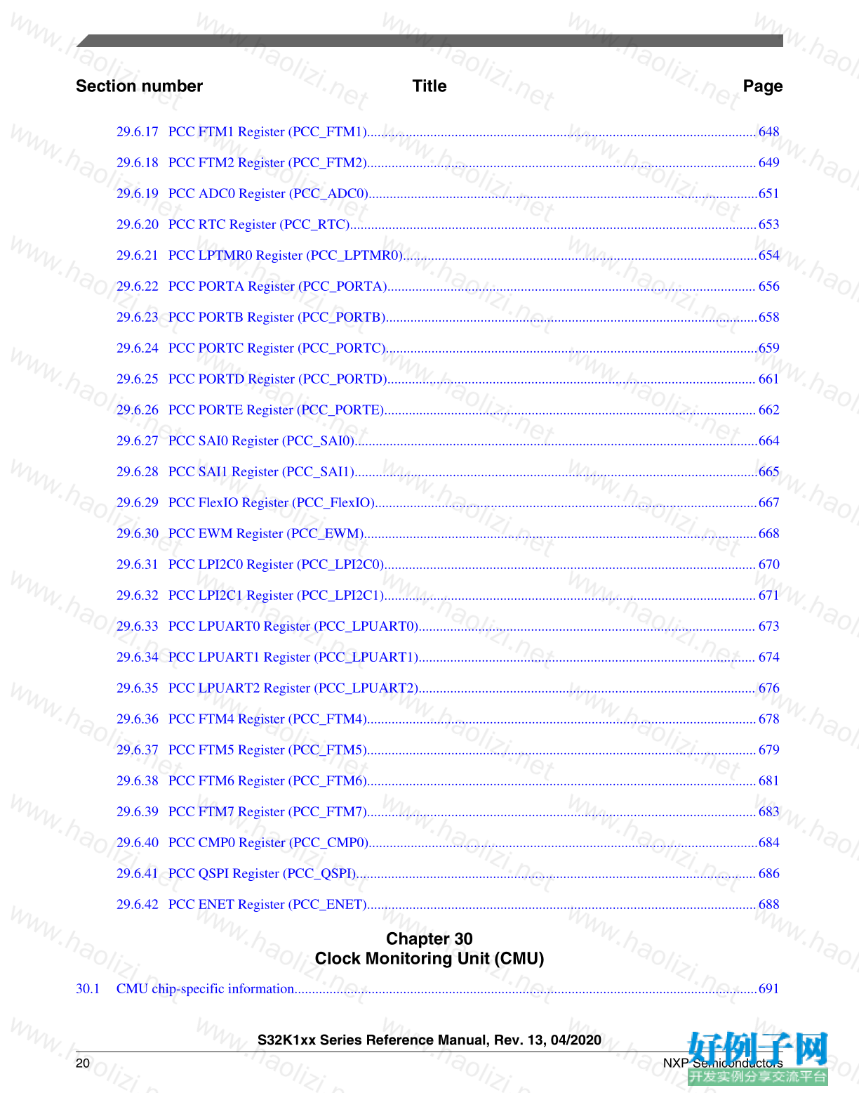
29.6.17 PCC FTM1 Register (PCC_FTM1)...............................................................................................................648
29.6.18 PCC FTM2 Register (PCC_FTM2)...............................................................................................................649
29.6.19 PCC ADC0 Register (PCC_ADC0)...............................................................................................................651
29.6.20 PCC RTC Register (PCC_RTC)....................................................................................................................653
29.6.21 PCC LPTMR0 Register (PCC_LPTMR0).....................................................................................................654
29.6.22 PCC PORTA Register (PCC_PORTA)......................................................................................................... 656
29.6.23 PCC PORTB Register (PCC_PORTB)..........................................................................................................658
29.6.24 PCC PORTC Register (PCC_PORTC)..........................................................................................................659
29.6.25 PCC PORTD Register (PCC_PORTD)......................................................................................................... 661
29.6.26 PCC PORTE Register (PCC_PORTE)..........................................................................................................662
29.6.27 PCC SAI0 Register (PCC_SAI0)...................................................................................................................664
29.6.28 PCC SAI1 Register (PCC_SAI1)...................................................................................................................665
29.6.29 PCC FlexIO Register (PCC_FlexIO).............................................................................................................667
29.6.30 PCC EWM Register (PCC_EWM)................................................................................................................668
29.6.31 PCC LPI2C0 Register (PCC_LPI2C0)..........................................................................................................670
29.6.32 PCC LPI2C1 Register (PCC_LPI2C1)..........................................................................................................671
29.6.33 PCC LPUART0 Register (PCC_LPUART0)................................................................................................ 673
29.6.34 PCC LPUART1 Register (PCC_LPUART1)................................................................................................ 674
29.6.35 PCC LPUART2 Register (PCC_LPUART2)................................................................................................ 676
29.6.36 PCC FTM4 Register (PCC_FTM4)...............................................................................................................678
29.6.37 PCC FTM5 Register (PCC_FTM5)...............................................................................................................679
29.6.38 PCC FTM6 Register (PCC_FTM6)...............................................................................................................681
29.6.39 PCC FTM7 Register (PCC_FTM7)...............................................................................................................683
29.6.40 PCC CMP0 Register (PCC_CMP0)...............................................................................................................684
29.6.41 PCC QSPI Register (PCC_QSPI)..................................................................................................................686
29.6.42 PCC ENET Register (PCC_ENET)...............................................................................................................688
Chapter 30
Clock Monitoring Unit (CMU)
30.1 CMU chip-specific information....................................................................................................................................691
S32K1xx Series Reference Manual, Rev. 13, 04/2020
20 NXP Semiconductors
Section number Title Page
30.2 Introduction...................................................................................................................................................................692
30.2.1 Basic operation...............................................................................................................................................693
30.2.2 Features..........................................................................................................................................................694
30.3 CMU_FC register descriptions.....................................................................................................................................694
30.3.1 CMU_FC Memory map.................................................................................................................................694
30.3.2 Global Configuration Register (GCR)...........................................................................................................695
30.3.3 Reference Count Configuration Register (RCCR).........................................................................................696
30.3.4 High Threshold Configuration Register (HTCR).......................................................................................... 697
30.3.5 Low Threshold Configuration Register (LTCR)........................................................................................... 698
30.3.6 Status Register (SR).......................................................................................................................................699
30.3.7 Interrupt Enable Register (IER).....................................................................................................................700
30.4 Functional description...................................................................................................................................................703
30.4.1 Monitored clock lost...................................................................................................................................... 703
30.5 Programming guidelines...............................................................................................................................................703
30.5.1 Programming HFREF and LFREF................................................................................................................ 703
30.5.2 Programming RCCR[REF_CNT]..................................................................................................................704
30.5.3 CMU_FC programming sequence.................................................................................................................705
Chapter 31
Memories and Memory Interfaces
31.1 Introduction...................................................................................................................................................................707
31.2 Flash Memory Controller and flash memory modules.................................................................................................707
31.3 SRAM configuration.....................................................................................................................................................708
31.3.1 SRAM sizes....................................................................................................................................................708
31.3.2 SRAM accessibility........................................................................................................................................709
31.3.3 SRAM arbitration and priority control...........................................................................................................710
31.3.4 SRAM retention: power modes and resets.....................................................................................................710
31.3.5 SRAM access: Behavior of device when in accessing a memory with multi-bit ECC error.........................711
Chapter 32
PRAM Controller (PRAMC)
S32K1xx Series Reference Manual, Rev. 13, 04/2020
NXP Semiconductors 21
Section number Title Page
32.1 PRAMC chip-specific information ..............................................................................................................................713
32.2 Introduction...................................................................................................................................................................713
32.3 Memory map and register definition.............................................................................................................................714
32.4 Functional description...................................................................................................................................................714
32.4.1 Error Correcting Code (ECC)........................................................................................................................714
32.4.2 Read/Write introduction.................................................................................................................................715
32.4.3 Reads..............................................................................................................................................................715
32.4.4 Writes.............................................................................................................................................................716
32.4.5 Late write hits.................................................................................................................................................717
32.5 Initialization / application information.........................................................................................................................718
Chapter 33
Local Memory Controller (LMEM)
33.1 Chip-specific LMEM information ...............................................................................................................................719
33.1.1 LMEM region description..............................................................................................................................719
33.1.2 LMEM SRAM sizes.......................................................................................................................................719
33.2 Introduction...................................................................................................................................................................719
33.2.1 Block Diagram...............................................................................................................................................720
33.2.2 Cache features................................................................................................................................................721
33.3 Memory Map/Register Definition.................................................................................................................................723
33.3.1 LMEM register descriptions.......................................................................................................................... 723
33.4 Functional Description..................................................................................................................................................732
33.4.1 LMEM Function............................................................................................................................................ 732
33.4.2 SRAM Function.............................................................................................................................................733
33.4.3 Cache Function.............................................................................................................................................. 735
33.4.4 Cache Control................................................................................................................................................ 736
Chapter 34
Miscellaneous System Control Module (MSCM)
34.1 Chip-specific MSCM information................................................................................................................................741
34.1.1 Chip-specific TMLSZ/TMUSZ information................................................................................................. 741
S32K1xx Series Reference Manual, Rev. 13, 04/2020
22 NXP Semiconductors
Section number Title Page
34.1.2 Chip-specific register information.................................................................................................................741
34.2 Overview.......................................................................................................................................................................742
34.3 Chip Configuration and Boot........................................................................................................................................742
34.4 MSCM Memory Map/Register Definition....................................................................................................................743
34.4.1 CPU Configuration Memory Map and Registers...........................................................................................743
34.4.2 MSCM register descriptions.......................................................................................................................... 743
Chapter 35
Flash Memory Controller (FMC)
35.1 Chip-specific FMC information....................................................................................................................................775
35.1.1 FMC masters..................................................................................................................................................775
35.1.2 Program flash and Data flash port width....................................................................................................... 776
35.1.3 ECC Implementation for NVM .....................................................................................................................776
35.2 Introduction...................................................................................................................................................................776
35.2.1 Overview........................................................................................................................................................776
35.2.2 Features..........................................................................................................................................................777
35.3 Modes of operation.......................................................................................................................................................778
35.4 External signal description............................................................................................................................................778
35.5 Functional description...................................................................................................................................................778
35.5.1 Default configuration.....................................................................................................................................778
35.5.2 Speculative reads............................................................................................................................................778
35.6 Initialization and application information.....................................................................................................................779
Chapter 36
Flash Memory Module (FTFC)
36.1 Chip-specific FTFC information...................................................................................................................................781
36.1.1 Flash memory types.......................................................................................................................................782
36.1.2 Flash memory sizes........................................................................................................................................782
36.1.3 Flash memory map.........................................................................................................................................801
36.1.4 Flash memory security...................................................................................................................................802
36.1.5 Power mode restrictions on flash memory programming..............................................................................802
S32K1xx Series Reference Manual, Rev. 13, 04/2020
NXP Semiconductors 23
Section number Title Page
36.1.6 Flash memory modes.....................................................................................................................................802
36.1.7 Erase all contents of flash memory................................................................................................................802
36.1.8 Customize MCU operations via FTFC_FOPT register..................................................................................803
36.1.9 Simultaneous operations on PFLASH read partitions .................................................................................. 803
36.2 Introduction...................................................................................................................................................................803
36.2.1 Features..........................................................................................................................................................804
36.2.2 Block diagram................................................................................................................................................806
36.2.3 Glossary......................................................................................................................................................... 807
36.3 External signal description............................................................................................................................................809
36.4 Memory map and registers............................................................................................................................................810
36.4.1 Flash configuration field description............................................................................................................. 810
36.4.2 Program flash 0 IFR map...............................................................................................................................810
36.4.3 Data flash 0 IFR map.....................................................................................................................................811
36.4.4 Register descriptions......................................................................................................................................812
36.5 Functional description...................................................................................................................................................830
36.5.1 Flash protection..............................................................................................................................................830
36.5.2 FlexNVM description.................................................................................................................................... 832
36.5.3 Interrupts........................................................................................................................................................835
36.5.4 Flash operation in low-power modes.............................................................................................................836
36.5.5 Functional modes of operation.......................................................................................................................836
36.5.6 Flash memory reads and ignored writes........................................................................................................ 836
36.5.7 Read while write (RWW).............................................................................................................................. 837
36.5.8 Flash program and erase................................................................................................................................ 837
36.5.9 FTFC command operations............................................................................................................................837
36.5.10 Margin read commands..................................................................................................................................844
36.5.11 Flash command descriptions..........................................................................................................................845
36.5.12 Security.......................................................................................................................................................... 871
36.5.13 Cryptographic Services Engine (CSEc).........................................................................................................873
36.5.14 Reset sequence...............................................................................................................................................911
S32K1xx Series Reference Manual, Rev. 13, 04/2020
24 NXP Semiconductors
Section number Title Page
Chapter 37
Flash Memory Module (FTFM)
37.1 Chip-specific FTFM information .................................................................................................................................913
37.2 Introduction...................................................................................................................................................................913
37.2.1 Features..........................................................................................................................................................914
37.2.2 Block diagram................................................................................................................................................916
37.2.3 Glossary......................................................................................................................................................... 916
37.3 External signal description............................................................................................................................................918
37.4 Memory map and registers............................................................................................................................................919
37.4.1 Flash configuration field description............................................................................................................. 919
37.4.2 Program flash 0 IFR map...............................................................................................................................920
37.4.3 Data flash 0 IFR map.....................................................................................................................................920
37.4.4 Register descriptions......................................................................................................................................921
37.5 Functional description...................................................................................................................................................942
37.5.1 Flash protection..............................................................................................................................................942
37.5.2 FlexMemory description................................................................................................................................944
37.5.3 Interrupts........................................................................................................................................................948
37.5.4 Flash operation in low-power modes.............................................................................................................948
37.5.5 Flash memory reads and ignored writes........................................................................................................ 949
37.5.6 Read while write (RWW).............................................................................................................................. 949
37.5.7 Flash program and erase................................................................................................................................ 950
37.5.8 Flash command operations.............................................................................................................................950
37.5.9 Flash command descriptions..........................................................................................................................958
37.5.10 Security.......................................................................................................................................................... 983
37.5.11 Cryptographic Services Engine (CSEc).........................................................................................................985
37.5.12 Reset sequence...............................................................................................................................................1024
Chapter 38
Quad Serial Peripheral Interface (QuadSPI)
38.1 Chip-specific QuadSPI information..............................................................................................................................1027
S32K1xx Series Reference Manual, Rev. 13, 04/2020
NXP Semiconductors 25
Section number Title Page
38.1.1 Overview........................................................................................................................................................1027
38.1.2 Memory size requirement ............................................................................................................................. 1027
38.1.3 QuadSPI register reset values........................................................................................................................ 1028
38.1.4 Use case..........................................................................................................................................................1028
38.1.5 Supported read modes....................................................................................................................................1028
38.1.6 External memory options...............................................................................................................................1029
38.1.7 Recommended software configuration.......................................................................................................... 1029
38.1.8 Recommended programming sequence.........................................................................................................1030
38.1.9 Clock ratio between QuadSPI clocks ............................................................................................................1030
38.1.10 QuadSPI_MCR[SCLKCFG] implementation ...............................................................................................1030
38.1.11 QuadSPI_SOCCR[SOCCFG] implementation .............................................................................................1031
38.2 Introduction...................................................................................................................................................................1033
38.2.1 Features..........................................................................................................................................................1033
38.2.2 Block Diagram...............................................................................................................................................1034
38.2.3 QuadSPI Modes of Operation........................................................................................................................1035
38.2.4 Acronyms and Abbreviations.........................................................................................................................1036
38.2.5 Glossary for QuadSPI module....................................................................................................................... 1036
38.3 External Signal Description..........................................................................................................................................1038
38.3.1 Driving External Signals................................................................................................................................1039
38.4 Memory Map and Register Definition..........................................................................................................................1041
38.4.1 Register Write Access....................................................................................................................................1041
38.4.2 Peripheral Bus Register Descriptions............................................................................................................ 1042
38.4.3 Serial Flash Address Assignment.................................................................................................................. 1086
38.5 Flash memory mapped AMBA bus..............................................................................................................................1087
38.5.1 AHB Bus Access Considerations...................................................................................................................1088
38.5.2 Memory Mapped Serial Flash Data - Individual Flash Mode on Flash A.....................................................1088
38.5.3 Memory Mapped Serial Flash Data - Individual Flash Mode on Flash B.....................................................1089
38.5.4 AHB RX Data Buffer (QSPI_ARDB0 to QSPI_ARDB31).......................................................................... 1090
38.6 Interrupt Signals............................................................................................................................................................1093
S32K1xx Series Reference Manual, Rev. 13, 04/2020
26 NXP Semiconductors
Section number Title Page
38.7 Functional Description..................................................................................................................................................1093
38.7.1 Serial Flash Access Schemes.........................................................................................................................1093
38.7.2 Normal Mode.................................................................................................................................................1094
38.7.3 HyperRAM Support.......................................................................................................................................1113
38.8 Initialization/Application Information..........................................................................................................................1114
38.8.1 Power Up and Reset.......................................................................................................................................1114
38.8.2 Available Status/Flag Information.................................................................................................................1114
38.8.3 Flash Device Selection...................................................................................................................................1117
38.8.4 DMA Usage................................................................................................................................................... 1117
38.9 Byte Ordering - Endianness..........................................................................................................................................1121
38.9.1 Programming Flash Data............................................................................................................................... 1122
38.9.2 Reading Flash Data into the RX Buffer.........................................................................................................1122
38.9.3 Reading Flash Data into the AHB Buffer......................................................................................................1123
38.10 Driving Flash Control Signals in Single and Dual Mode.............................................................................................1124
38.11 Serial Flash Devices......................................................................................................................................................1124
38.11.1 Example Sequences........................................................................................................................................1124
38.12 Sampling of Serial Flash Input Data.............................................................................................................................1130
38.12.1 Basic Description...........................................................................................................................................1130
38.12.2 Supported read modes....................................................................................................................................1131
38.12.3 Data Strobe (DQS) sampling method............................................................................................................ 1134
38.13 Data Input Hold Requirement of Flash.........................................................................................................................1137
Chapter 39
Power Management
39.1 Introduction...................................................................................................................................................................1139
39.2 Power modes description..............................................................................................................................................1139
39.3 Entering and exiting power modes............................................................................................................................... 1141
39.4 Clocking modes............................................................................................................................................................ 1141
39.4.1 Clock gating...................................................................................................................................................1141
39.4.2 Stop mode options..........................................................................................................................................1141
S32K1xx Series Reference Manual, Rev. 13, 04/2020
NXP Semiconductors 27
Section number Title Page
39.4.3 DMA wake-up................................................................................................................................................1142
39.4.4 Compute Operation (CPO).............................................................................................................................1143
39.4.5 Peripheral Doze..............................................................................................................................................1144
39.5 Power mode transitions.................................................................................................................................................1145
39.6 Shutdown sequencing for power modes.......................................................................................................................1146
39.7 Power mode restrictions on flash memory programming.............................................................................................1146
39.8 Module operation in available power modes................................................................................................................1147
39.9 QuadSPI, Ethernet, and SAI operation ........................................................................................................................1150
Chapter 40
System Mode Controller (SMC)
40.1 Introduction...................................................................................................................................................................1151
40.2 Modes of operation.......................................................................................................................................................1151
40.3 Memory map and register descriptions.........................................................................................................................1153
40.3.1 SMC Version ID Register (SMC_VERID)....................................................................................................1154
40.3.2 SMC Parameter Register (SMC_PARAM)................................................................................................... 1155
40.3.3 Power Mode Protection register (SMC_PMPROT).......................................................................................1156
40.3.4 Power Mode Control register (SMC_PMCTRL)...........................................................................................1157
40.3.5 Stop Control Register (SMC_STOPCTRL)...................................................................................................1159
40.3.6 Power Mode Status register (SMC_PMSTAT)............................................................................................. 1161
40.4 Functional description...................................................................................................................................................1161
40.4.1 Power mode transitions..................................................................................................................................1162
40.4.2 Power mode entry/exit sequencing................................................................................................................1163
40.4.3 Run modes......................................................................................................................................................1166
40.4.4 Stop modes.....................................................................................................................................................1168
40.4.5 Debug in low power modes........................................................................................................................... 1169
Chapter 41
Power Management Controller (PMC)
41.1 Chip-specific PMC information ...................................................................................................................................1171
41.2 Modes supported...........................................................................................................................................................1171
S32K1xx Series Reference Manual, Rev. 13, 04/2020
28 NXP Semiconductors
Section number Title Page
41.2.1 LVD, LVW and LVR threshold levels.......................................................................................................... 1171
41.3 Introduction...................................................................................................................................................................1171
41.4 Features.........................................................................................................................................................................1171
41.5 Modes of Operation......................................................................................................................................................1172
41.5.1 Full Performance Mode (FPM)......................................................................................................................1172
41.5.2 Low Power Mode (LPM)...............................................................................................................................1172
41.6 Low Voltage Detect (LVD) System............................................................................................................................. 1172
41.6.1 Low Voltage Reset (LVR) Operation............................................................................................................1173
41.6.2 LVD Interrupt Operation............................................................................................................................... 1173
41.6.3 Low-voltage warning (LVW) interrupt operation......................................................................................... 1173
41.7 Memory Map and Register Definition..........................................................................................................................1174
41.7.1 PMC register descriptions..............................................................................................................................1174
Chapter 42
Power Management Controller (PMC)
42.1 Chip-specific PMC information ...................................................................................................................................1181
42.2 Introduction...................................................................................................................................................................1181
42.3 Features.........................................................................................................................................................................1181
42.4 Modes of Operation......................................................................................................................................................1181
42.4.1 Full Performance Mode (FPM)......................................................................................................................1181
42.4.2 Low Power Mode (LPM)...............................................................................................................................1182
42.5 Low Voltage Reset and Detect System.........................................................................................................................1182
42.5.1 Low Voltage Reset (LVR) Operation............................................................................................................1182
42.5.2 Low-voltage warning (LVW) interrupt operation......................................................................................... 1182
42.6 Memory Map and Register Definition..........................................................................................................................1183
42.6.1 PMC register descriptions..............................................................................................................................1183
Chapter 43
ADC Configuration
43.1 Instantiation information...............................................................................................................................................1191
43.1.1 Number of ADC channels..............................................................................................................................1191
S32K1xx Series Reference Manual, Rev. 13, 04/2020
NXP Semiconductors 29
Section number Title Page
43.1.2 ADC Connections/Channel Assignment........................................................................................................1192
43.2 Register implementation...............................................................................................................................................1193
43.3 DMA Support on ADC.................................................................................................................................................1193
43.4 ADC Hardware Interleaved Channels.......................................................................................................................... 1194
43.5 ADC internal supply monitoring.................................................................................................................................. 1195
43.6 ADC Reference Options...............................................................................................................................................1195
43.7 ADC Trigger Sources................................................................................................................................................... 1196
43.7.1 PDB triggering scheme..................................................................................................................................1198
43.7.2 TRGMUX trigger scheme..............................................................................................................................1199
43.8 Trigger Selection...........................................................................................................................................................1200
43.9 Trigger Latching and Arbitration..................................................................................................................................1201
43.10 ADC triggering configurations ....................................................................................................................................1203
43.11 ADC low-power modes................................................................................................................................................1210
43.12 ADC Trigger Concept – Use Case................................................................................................................................1210
43.13 ADC calibration scheme...............................................................................................................................................1212
43.14 S32K11X to S32K14X difference ...............................................................................................................................1213
Chapter 44
Analog-to-Digital Converter (ADC)
44.1 Chip-specific ADC information....................................................................................................................................1215
44.2 Introduction...................................................................................................................................................................1215
44.2.1 Features..........................................................................................................................................................1215
44.2.2 Block diagram................................................................................................................................................1216
44.3 ADC signal descriptions...............................................................................................................................................1217
44.3.1 Analog Power (VDDA)................................................................................................................................. 1217
44.3.2 Analog Ground (VSSA).................................................................................................................................1217
44.3.3 Voltage Reference Select...............................................................................................................................1217
44.3.4 Analog Channel Inputs (ADx).......................................................................................................................1218
44.4 ADC register descriptions.............................................................................................................................................1218
44.4.1 ADC Memory map.........................................................................................................................................1218
S32K1xx Series Reference Manual, Rev. 13, 04/2020
30 NXP Semiconductors
Section number Title Page
44.4.2 ADC Status and Control Register 1 (SC1A - aSC1P)................................................................................... 1220
44.4.3 ADC Configuration Register 1 (CFG1).........................................................................................................1223
44.4.4 ADC Configuration Register 2 (CFG2).........................................................................................................1225
44.4.5 ADC Data Result Registers (RA - aRP)........................................................................................................ 1226
44.4.6 Compare Value Registers (CV1 - CV2)........................................................................................................ 1228
44.4.7 Status and Control Register 2 (SC2)..............................................................................................................1229
44.4.8 Status and Control Register 3 (SC3)..............................................................................................................1232
44.4.9 BASE Offset Register (BASE_OFS).............................................................................................................1233
44.4.10 ADC Offset Correction Register (OFS).........................................................................................................1234
44.4.11 USER Offset Correction Register (USR_OFS).............................................................................................1235
44.4.12 ADC X Offset Correction Register (XOFS)..................................................................................................1236
44.4.13 ADC Y Offset Correction Register (YOFS)..................................................................................................1237
44.4.14 ADC Gain Register (G)..................................................................................................................................1238
44.4.15 ADC User Gain Register (UG)......................................................................................................................1240
44.4.16 ADC General Calibration Value Register S (CLPS).....................................................................................1241
44.4.17 ADC Plus-Side General Calibration Value Register 3 (CLP3)..................................................................... 1242
44.4.18 ADC Plus-Side General Calibration Value Register 2 (CLP2)..................................................................... 1243
44.4.19 ADC Plus-Side General Calibration Value Register 1 (CLP1)..................................................................... 1243
44.4.20 ADC Plus-Side General Calibration Value Register 0 (CLP0)..................................................................... 1244
44.4.21 ADC Plus-Side General Calibration Value Register X (CLPX)....................................................................1245
44.4.22 ADC Plus-Side General Calibration Value Register 9 (CLP9)..................................................................... 1246
44.4.23 ADC General Calibration Offset Value Register S (CLPS_OFS).................................................................1247
44.4.24 ADC Plus-Side General Calibration Offset Value Register 3 (CLP3_OFS).................................................1248
44.4.25 ADC Plus-Side General Calibration Offset Value Register 2 (CLP2_OFS).................................................1249
44.4.26 ADC Plus-Side General Calibration Offset Value Register 1 (CLP1_OFS).................................................1250
44.4.27 ADC Plus-Side General Calibration Offset Value Register 0 (CLP0_OFS).................................................1251
44.4.28 ADC Plus-Side General Calibration Offset Value Register X (CLPX_OFS)...............................................1252
44.4.29 ADC Plus-Side General Calibration Offset Value Register 9 (CLP9_OFS).................................................1253
44.4.30 ADC Status and Control Register 1 (SC1AA - SC1Z)..................................................................................1254
S32K1xx Series Reference Manual, Rev. 13, 04/2020
NXP Semiconductors 31
Section number Title Page
44.4.31 ADC Data Result Registers (RAA - RZ).......................................................................................................1257
44.5 Functional description...................................................................................................................................................1259
44.5.1 Clock select and divide control......................................................................................................................1259
44.5.2 Voltage reference selection............................................................................................................................1260
44.5.3 Hardware trigger and channel selects............................................................................................................ 1260
44.5.4 Conversion control.........................................................................................................................................1261
44.5.5 Automatic compare function..........................................................................................................................1265
44.5.6 Calibration function....................................................................................................................................... 1266
44.5.7 User-defined offset function.......................................................................................................................... 1267
44.5.8 MCU Normal Stop mode operation...............................................................................................................1268
Chapter 45
Comparator (CMP)
45.1 Chip-specific CMP information....................................................................................................................................1269
45.1.1 Instantiation information................................................................................................................................1269
45.1.2 CMP input connections..................................................................................................................................1269
45.1.3 CMP external references................................................................................................................................1271
45.1.4 External window/sample input.......................................................................................................................1271
45.1.5 CMP trigger mode..........................................................................................................................................1271
45.1.6 Programming recommendation......................................................................................................................1272
45.1.7 S32K11X to S32K14X difference ................................................................................................................ 1272
45.2 Introduction...................................................................................................................................................................1273
45.3 Features.........................................................................................................................................................................1273
45.3.1 CMP features..................................................................................................................................................1273
45.3.2 8-bit DAC key features..................................................................................................................................1274
45.3.3 ANMUX key features....................................................................................................................................1274
45.4 CMP, DAC, and ANMUX diagram..............................................................................................................................1275
45.5 CMP block diagram......................................................................................................................................................1276
45.6 CMP pin descriptions....................................................................................................................................................1278
45.6.1 External pins.................................................................................................................................................. 1278
S32K1xx Series Reference Manual, Rev. 13, 04/2020
32 NXP Semiconductors
Section number Title Page
45.7 CMP functional modes................................................................................................................................................. 1279
45.7.1 Disabled mode (# 1).......................................................................................................................................1280
45.7.2 Continuous mode (#s 2A & 2B).................................................................................................................... 1281
45.7.3 Sampled, Non-Filtered mode (#s 3A & 3B)..................................................................................................1281
45.7.4 Sampled, Filtered mode (#s 4A & 4B).......................................................................................................... 1283
45.7.5 Windowed mode (#s 5A & 5B)..................................................................................................................... 1285
45.7.6 Windowed/Resampled mode (# 6).................................................................................................................1287
45.7.7 Windowed/Filtered mode (#7).......................................................................................................................1288
45.8 Memory map/register definitions..................................................................................................................................1289
45.8.1 CMP Control Register 0 (CMP_C0)..............................................................................................................1289
45.8.2 CMP Control Register 1 (CMP_C1)..............................................................................................................1293
45.8.3 CMP Control Register 2 (CMP_C2)..............................................................................................................1296
45.9 CMP functional description..........................................................................................................................................1298
45.9.1 Initialization...................................................................................................................................................1298
45.9.2 Low-pass filter............................................................................................................................................... 1299
45.10 Interrupts.......................................................................................................................................................................1301
45.11 DMA support................................................................................................................................................................1301
45.12 DAC functional description..........................................................................................................................................1302
45.12.1 Digital-to-analog converter block diagram....................................................................................................1302
45.12.2 DAC resets.....................................................................................................................................................1302
45.12.3 DAC clocks....................................................................................................................................................1303
45.12.4 DAC interrupts...............................................................................................................................................1303
45.13 Trigger mode.................................................................................................................................................................1303
Chapter 46
Programmable delay block (PDB)
46.1 Chip-specific PDB information....................................................................................................................................1307
46.1.1 Instantiation Information................................................................................................................................1307
46.1.2 PDB trigger interconnections with ADC and TRGMUX..............................................................................1308
46.1.3 Back-to-back acknowledgement connections................................................................................................1308
S32K1xx Series Reference Manual, Rev. 13, 04/2020
NXP Semiconductors 33
Section number Title Page
46.1.4 Pulse-Out Enable Register Implementation...................................................................................................1318
46.1.5 S32K11X to S32K14X difference ................................................................................................................ 1318
46.2 Introduction...................................................................................................................................................................1318
46.2.1 Features..........................................................................................................................................................1318
46.2.2 Implementation.............................................................................................................................................. 1319
46.2.3 Back-to-back acknowledgment connections..................................................................................................1320
46.2.4 Block diagram................................................................................................................................................1320
46.2.5 Modes of operation........................................................................................................................................ 1321
46.3 Memory map and register definition.............................................................................................................................1322
46.3.1 Status and Control register (PDB_SC)...........................................................................................................1324
46.3.2 Modulus register (PDB_MOD)......................................................................................................................1327
46.3.3 Counter register (PDB_CNT)........................................................................................................................ 1328
46.3.4 Interrupt Delay register (PDB_IDLY)...........................................................................................................1328
46.3.5 Channel n Control register 1 (PDB_CHnC1)................................................................................................ 1329
46.3.6 Channel n Status register (PDB_CHnS)........................................................................................................ 1330
46.3.7 Channel n Delay 0 register (PDB_CHnDLY0)..............................................................................................1330
46.3.8 Channel n Delay 1 register (PDB_CHnDLY1)..............................................................................................1331
46.3.9 Channel n Delay 2 register (PDB_CHnDLY2)..............................................................................................1332
46.3.10 Channel n Delay 3 register (PDB_CHnDLY3)..............................................................................................1332
46.3.11 Channel n Delay 4 register (PDB_CHnDLY4)..............................................................................................1333
46.3.12 Channel n Delay 5 register (PDB_CHnDLY5)..............................................................................................1334
46.3.13 Channel n Delay 6 register (PDB_CHnDLY6)..............................................................................................1334
46.3.14 Channel n Delay 7 register (PDB_CHnDLY7)..............................................................................................1335
46.3.15 Pulse-Out n Enable register (PDB_POEN)....................................................................................................1335
46.3.16 Pulse-Out n Delay register (PDB_POnDLY)................................................................................................ 1336
46.4 Functional description...................................................................................................................................................1336
46.4.1 PDB pre-trigger and trigger outputs...............................................................................................................1336
46.4.2 PDB trigger input source selection................................................................................................................ 1339
46.4.3 Pulse-Out's..................................................................................................................................................... 1339
S32K1xx Series Reference Manual, Rev. 13, 04/2020
34 NXP Semiconductors
Section number Title Page
46.4.4 Updating the delay registers...........................................................................................................................1340
46.4.5 Interrupts........................................................................................................................................................1342
46.4.6 DMA.............................................................................................................................................................. 1342
46.5 Application information................................................................................................................................................1342
46.5.1 Impact of using the prescaler and multiplication factor on timing resolution...............................................1342
Chapter 47
FlexTimer Module (FTM)
47.1 Chip-specific FTM information....................................................................................................................................1345
47.1.1 Instantiation Information................................................................................................................................1345
47.1.2 FTM Interrupts...............................................................................................................................................1346
47.1.3 FTM Fault Detection Inputs...........................................................................................................................1347
47.1.4 FTM Hardware Triggers and Synchronization..............................................................................................1348
47.1.5 FTM Input Capture Options...........................................................................................................................1350
47.1.6 FTM Hall sensor support............................................................................................................................... 1351
47.1.7 FTM Modulation Implementation................................................................................................................. 1351
47.1.8 FTM Global Time Base................................................................................................................................. 1352
47.1.9 FTM BDM and debug halt mode...................................................................................................................1353
47.1.10 S32K11X to S32K14X difference ................................................................................................................ 1353
47.2 Introduction...................................................................................................................................................................1355
47.2.1 Features..........................................................................................................................................................1355
47.2.2 Modes of operation........................................................................................................................................ 1356
47.2.3 Block Diagram...............................................................................................................................................1357
47.3 FTM signal descriptions............................................................................................................................................... 1359
47.4 Memory map and register definition.............................................................................................................................1359
47.4.1 Memory map..................................................................................................................................................1359
47.4.2 Register descriptions......................................................................................................................................1360
47.4.3 FTM register descriptions..............................................................................................................................1360
47.5 Functional Description..................................................................................................................................................1417
47.5.1 Clock source...................................................................................................................................................1417
S32K1xx Series Reference Manual, Rev. 13, 04/2020
NXP Semiconductors 35
Section number Title Page
47.5.2 Prescaler.........................................................................................................................................................1417
47.5.3 Counter...........................................................................................................................................................1418
47.5.4 Channel Modes.............................................................................................................................................. 1424
47.5.5 Input Capture Mode.......................................................................................................................................1426
47.5.6 Output Compare mode...................................................................................................................................1431
47.5.7 Edge-Aligned PWM (EPWM) mode.............................................................................................................1432
47.5.8 Center-Aligned PWM (CPWM) mode.......................................................................................................... 1434
47.5.9 Combine mode...............................................................................................................................................1436
47.5.10 Modified Combine PWM Mode....................................................................................................................1444
47.5.11 Complementary Mode....................................................................................................................................1447
47.5.12 Registers updated from write buffers.............................................................................................................1449
47.5.13 PWM synchronization....................................................................................................................................1450
47.5.14 Inverting.........................................................................................................................................................1466
47.5.15 Software Output Control Mode......................................................................................................................1467
47.5.16 Deadtime insertion.........................................................................................................................................1469
47.5.17 Output mask...................................................................................................................................................1473
47.5.18 Fault Control..................................................................................................................................................1474
47.5.19 Polarity Control..............................................................................................................................................1478
47.5.20 Initialization...................................................................................................................................................1479
47.5.21 Features Priority.............................................................................................................................................1479
47.5.22 External Trigger.............................................................................................................................................1480
47.5.23 Initialization Trigger......................................................................................................................................1481
47.5.24 Capture Test Mode.........................................................................................................................................1483
47.5.25 DMA.............................................................................................................................................................. 1484
47.5.26 Dual Edge Capture Mode...............................................................................................................................1485
47.5.27 Quadrature Decoder Mode.............................................................................................................................1493
47.5.28 Debug mode...................................................................................................................................................1499
47.5.29 Reload Points................................................................................................................................................. 1500
47.5.30 Global Load....................................................................................................................................................1503
S32K1xx Series Reference Manual, Rev. 13, 04/2020
36 NXP Semiconductors
Section number Title Page
47.5.31 Global time base (GTB).................................................................................................................................1504
47.5.32 Channel trigger output................................................................................................................................... 1505
47.5.33 External Control of Channels Output.............................................................................................................1506
47.5.34 Dithering........................................................................................................................................................ 1506
47.6 Reset Overview.............................................................................................................................................................1517
47.7 FTM Interrupts..............................................................................................................................................................1519
47.7.1 Timer Overflow Interrupt...............................................................................................................................1519
47.7.2 Reload Point Interrupt....................................................................................................................................1519
47.7.3 Channel (n) Interrupt......................................................................................................................................1519
47.7.4 Fault Interrupt................................................................................................................................................ 1519
47.8 Initialization Procedure.................................................................................................................................................1520
Chapter 48
Low Power Interrupt Timer (LPIT)
48.1 Chip-specific LPIT information....................................................................................................................................1523
48.1.1 Instantiation Information................................................................................................................................1523
48.1.2 LPIT/DMA Periodic Trigger Assignments ...................................................................................................1523
48.1.3 LPIT input triggers ........................................................................................................................................1524
48.1.4 LPIT/ADC Trigger.........................................................................................................................................1524
48.1.5 Current timer value........................................................................................................................................ 1525
48.1.6 S32K11X to S32K14X difference ................................................................................................................ 1526
48.2 Introduction...................................................................................................................................................................1526
48.2.1 Overview........................................................................................................................................................1526
48.2.2 Block Diagram...............................................................................................................................................1527
48.3 Modes of operation.......................................................................................................................................................1528
48.4 Memory Map and Registers..........................................................................................................................................1529
48.4.1 LPIT register descriptions..............................................................................................................................1529
48.5 Functional description...................................................................................................................................................1545
48.5.1 LPIT programming model............................................................................................................................. 1545
48.5.2 Initialization...................................................................................................................................................1546
S32K1xx Series Reference Manual, Rev. 13, 04/2020
NXP Semiconductors 37
Section number Title Page
48.5.3 Timer Modes..................................................................................................................................................1547
48.5.4 Trigger Control for Timers............................................................................................................................ 1548
48.5.5 Channel Chaining...........................................................................................................................................1549
48.5.6 Detailed timing...............................................................................................................................................1549
Chapter 49
Low Power Timer (LPTMR)
49.1 Chip-specific LPTMR information...............................................................................................................................1563
49.1.1 Instantiation Information................................................................................................................................1563
49.1.2 LPTMR pulse counter input options..............................................................................................................1564
49.1.3 S32K11X to S32K14X difference ................................................................................................................ 1564
49.2 Introduction...................................................................................................................................................................1564
49.2.1 Features..........................................................................................................................................................1564
49.2.2 Modes of operation........................................................................................................................................ 1565
49.3 LPTMR signal descriptions..........................................................................................................................................1565
49.3.1 Detailed signal descriptions...........................................................................................................................1565
49.4 Memory map and register definition.............................................................................................................................1566
49.4.1 LPTMR register descriptions.........................................................................................................................1566
49.5 Functional description...................................................................................................................................................1571
49.5.1 LPTMR power and reset................................................................................................................................1571
49.5.2 LPTMR clocking............................................................................................................................................1572
49.5.3 LPTMR prescaler/glitch filter........................................................................................................................1572
49.5.4 LPTMR counter............................................................................................................................................. 1573
49.5.5 LPTMR compare............................................................................................................................................1574
49.5.6 LPTMR interrupt............................................................................................................................................1574
49.5.7 LPTMR hardware trigger...............................................................................................................................1575
Chapter 50
Real Time Clock (RTC)
50.1 Chip-specific RTC information....................................................................................................................................1577
50.1.1 RTC instantiation...........................................................................................................................................1577
S32K1xx Series Reference Manual, Rev. 13, 04/2020
38 NXP Semiconductors
Section number Title Page
50.1.2 RTC interrupts ...............................................................................................................................................1577
50.1.3 Software recommendation............................................................................................................................. 1577
50.1.4 Multiple trigger .............................................................................................................................................1578
50.1.5 S32K11X to S32K14X difference ................................................................................................................ 1578
50.2 Introduction...................................................................................................................................................................1578
50.2.1 Features..........................................................................................................................................................1578
50.2.2 Modes of operation........................................................................................................................................ 1578
50.2.3 RTC signal descriptions.................................................................................................................................1579
50.3 Register definition.........................................................................................................................................................1579
50.3.1 RTC register descriptions...............................................................................................................................1579
50.4 Functional description...................................................................................................................................................1590
50.4.1 Power, clocking, and reset............................................................................................................................. 1590
50.4.2 Time counter..................................................................................................................................................1591
50.4.3 Compensation.................................................................................................................................................1591
50.4.4 Time alarm.....................................................................................................................................................1592
50.4.5 Update mode..................................................................................................................................................1593
50.4.6 Register lock.................................................................................................................................................. 1593
50.4.7 Interrupt..........................................................................................................................................................1593
Chapter 51
Low Power Serial Peripheral Interface (LPSPI)
51.1 Chip-specific LPSPI information..................................................................................................................................1595
51.1.1 Instantiation Information................................................................................................................................1595
51.2 Introduction...................................................................................................................................................................1596
51.2.1 Features..........................................................................................................................................................1596
51.2.2 Block Diagram...............................................................................................................................................1597
51.2.3 Modes of operation........................................................................................................................................ 1598
51.2.4 Signal Descriptions........................................................................................................................................1598
51.3 Memory Map and Registers..........................................................................................................................................1599
51.3.1 LPSPI register descriptions............................................................................................................................1599
S32K1xx Series Reference Manual, Rev. 13, 04/2020
NXP Semiconductors 39
Section number Title Page
51.4 Functional description...................................................................................................................................................1624
51.4.1 Clocking and resets........................................................................................................................................1624
51.4.2 Master Mode..................................................................................................................................................1624
51.4.3 Slave Mode.................................................................................................................................................... 1630
51.4.4 Interrupts and DMA Requests........................................................................................................................1632
51.4.5 Peripheral Triggers.........................................................................................................................................1633
Chapter 52
Low Power Inter-Integrated Circuit (LPI2C)
52.1 Chip-specific LPI2C information................................................................................................................................. 1635
52.1.1 Instantiation information................................................................................................................................1635
52.2 Introduction...................................................................................................................................................................1636
52.2.1 Features..........................................................................................................................................................1636
52.2.2 Block Diagram...............................................................................................................................................1637
52.2.3 Modes of operation........................................................................................................................................ 1638
52.2.4 Signal Descriptions........................................................................................................................................1638
52.3 Functional description...................................................................................................................................................1639
52.3.1 Clocking and Resets.......................................................................................................................................1639
52.3.2 Master Mode..................................................................................................................................................1640
52.3.3 Slave Mode.................................................................................................................................................... 1646
52.3.4 Interrupts and DMA Requests........................................................................................................................1648
52.3.5 Peripheral Triggers.........................................................................................................................................1650
52.4 Memory Map and Registers..........................................................................................................................................1651
52.4.1 LPI2C register descriptions............................................................................................................................1651
Chapter 53
Low Power Universal Asynchronous Receiver/Transmitter (LPUART)
53.1 Chip-specific LPUART information.............................................................................................................................1691
53.1.1 Instantiation Information................................................................................................................................1691
53.2 Introduction...................................................................................................................................................................1692
53.2.1 Features..........................................................................................................................................................1692
S32K1xx Series Reference Manual, Rev. 13, 04/2020
40 NXP Semiconductors
Section number Title Page
53.2.2 Modes of operation........................................................................................................................................ 1693
53.2.3 Signal Descriptions........................................................................................................................................1693
53.2.4 Block diagram................................................................................................................................................1693
53.3 Register definition.........................................................................................................................................................1695
53.3.1 LPUART register descriptions.......................................................................................................................1695
53.4 Functional description...................................................................................................................................................1721
53.4.1 Clocking and Resets.......................................................................................................................................1721
53.4.2 Baud rate generation...................................................................................................................................... 1721
53.4.3 Transmitter functional description.................................................................................................................1722
53.4.4 Receiver functional description..................................................................................................................... 1725
53.4.5 Additional LPUART functions......................................................................................................................1733
53.4.6 Infrared interface............................................................................................................................................1735
53.4.7 Interrupts and status flags.............................................................................................................................. 1736
53.4.8 Peripheral Triggers.........................................................................................................................................1737
Chapter 54
Flexible I/O (FlexIO)
54.1 Chip-specific FlexIO information.................................................................................................................................1739
54.1.1 FlexIO Configuration.....................................................................................................................................1739
54.2 Introduction...................................................................................................................................................................1739
54.2.1 Overview........................................................................................................................................................1739
54.2.2 Features..........................................................................................................................................................1740
54.2.3 Block Diagram...............................................................................................................................................1740
54.2.4 Modes of operation........................................................................................................................................ 1741
54.2.5 FlexIO Signal Descriptions............................................................................................................................1741
54.3 Memory Map and Registers..........................................................................................................................................1742
54.3.1 FLEXIO register descriptions........................................................................................................................1742
54.4 Functional description...................................................................................................................................................1766
54.4.1 Clocking and Resets.......................................................................................................................................1766
54.4.2 Shifter operation.............................................................................................................................................1767
S32K1xx Series Reference Manual, Rev. 13, 04/2020
NXP Semiconductors 41
Section number Title Page
54.4.3 Timer Operation.............................................................................................................................................1769
54.4.4 Pin operation..................................................................................................................................................1773
54.4.5 Interrupts and DMA Requests........................................................................................................................1774
54.4.6 Peripheral Triggers.........................................................................................................................................1774
54.5 Application Information................................................................................................................................................1775
54.5.1 UART Transmit............................................................................................................................................. 1775
54.5.2 UART Receive...............................................................................................................................................1776
54.5.3 SPI Master......................................................................................................................................................1778
54.5.4 SPI Slave........................................................................................................................................................1780
54.5.5 I2C Master......................................................................................................................................................1781
54.5.6 I2S Master......................................................................................................................................................1783
54.5.7 I2S Slave........................................................................................................................................................1785
Chapter 55
FlexCAN
55.1 Chip-specific FlexCAN information.............................................................................................................................1787
55.1.1 Instantiation information................................................................................................................................1787
55.1.2 FlexCAN register information.......................................................................................................................1788
55.1.3 Reset value of MDIS bit.................................................................................................................................1795
55.1.4 FlexCAN external time tick ..........................................................................................................................1795
55.1.5 FlexCAN Interrupts........................................................................................................................................1795
55.1.6 FlexCAN Operation in Low Power Modes....................................................................................................1796
55.1.7 FlexCAN oscillator clock...............................................................................................................................1796
55.1.8 Supported baud rate ...................................................................................................................................... 1796
55.1.9 Requirements for entering FlexCAN modes: Freeze, Disable, Stop............................................................. 1796
55.2 Introduction...................................................................................................................................................................1798
55.2.1 Overview........................................................................................................................................................1799
55.2.2 FlexCAN module features............................................................................................................................. 1800
55.2.3 Modes of operation........................................................................................................................................ 1801
55.3 FlexCAN signal descriptions........................................................................................................................................1803
S32K1xx Series Reference Manual, Rev. 13, 04/2020
42 NXP Semiconductors
Section number Title Page
55.3.1 CAN Rx .........................................................................................................................................................1803
55.3.2 CAN Tx .........................................................................................................................................................1804
55.4 Memory map/register definition...................................................................................................................................1804
55.4.1 FlexCAN memory mapping...........................................................................................................................1804
55.4.2 CAN register descriptions..............................................................................................................................1805
55.4.3 Message buffer structure................................................................................................................................1876
55.4.4 FlexCAN memory partition for CAN FD......................................................................................................1883
55.4.5 FlexCAN message buffer memory map.........................................................................................................1884
55.4.6 Rx FIFO structure.......................................................................................................................................... 1886
55.5 Functional description...................................................................................................................................................1889
55.5.1 Transmit process............................................................................................................................................1889
55.5.2 Arbitration process.........................................................................................................................................1891
55.5.3 Receive process..............................................................................................................................................1894
55.5.4 Matching process........................................................................................................................................... 1896
55.5.5 Receive process under Pretended Networking mode.....................................................................................1901
55.5.6 Move process................................................................................................................................................. 1905
55.5.7 Data coherence...............................................................................................................................................1907
55.5.8 Rx FIFO......................................................................................................................................................... 1910
55.5.9 CAN protocol related features....................................................................................................................... 1913
55.5.10 Clock domains and restrictions......................................................................................................................1933
55.5.11 Modes of operation details.............................................................................................................................1937
55.5.12 Interrupts........................................................................................................................................................1940
55.5.13 Bus interface.................................................................................................................................................. 1942
55.6 Initialization/application information...........................................................................................................................1943
55.6.1 FlexCAN initialization sequence...................................................................................................................1943
Chapter 56
Synchronous Audio Interface (SAI)
56.1 Chip-specific SAI information .....................................................................................................................................1945
56.1.1 SAI configuration...........................................................................................................................................1945
S32K1xx Series Reference Manual, Rev. 13, 04/2020
NXP Semiconductors 43
Section number Title Page
56.1.2 Chip-specific register information.................................................................................................................1946
56.2 Introduction...................................................................................................................................................................1947
56.2.1 Features..........................................................................................................................................................1947
56.2.2 Block diagram................................................................................................................................................1947
56.2.3 Modes of operation........................................................................................................................................ 1948
56.3 External signals.............................................................................................................................................................1949
56.4 Memory map and register definition.............................................................................................................................1949
56.4.1 I2S register descriptions.................................................................................................................................1949
56.5 Functional description...................................................................................................................................................1982
56.5.1 SAI clocking.................................................................................................................................................. 1982
56.5.2 SAI resets.......................................................................................................................................................1984
56.5.3 Synchronous modes....................................................................................................................................... 1985
56.5.4 Frame sync configuration...............................................................................................................................1986
56.5.5 Data FIFO...................................................................................................................................................... 1986
56.5.6 Word mask register........................................................................................................................................1990
56.5.7 Interrupts and DMA requests.........................................................................................................................1991
Chapter 57
Ethernet MAC (ENET)
57.1 Chip-specific ENET information..................................................................................................................................1995
57.1.1 Software guideline during ENET operation...................................................................................................1995
57.2 Introduction...................................................................................................................................................................1995
57.3 Overview.......................................................................................................................................................................1996
57.3.1 Features..........................................................................................................................................................1996
57.3.2 Block diagram................................................................................................................................................1999
57.4 External signal description............................................................................................................................................1999
57.5 Memory map/register definition...................................................................................................................................2001
57.5.1 Interrupt Event Register (ENET_EIR)...........................................................................................................2006
57.5.2 Interrupt Mask Register (ENET_EIMR)........................................................................................................2009
57.5.3 Receive Descriptor Active Register (ENET_RDAR)....................................................................................2012
S32K1xx Series Reference Manual, Rev. 13, 04/2020
44 NXP Semiconductors
Section number Title Page
57.5.4 Transmit Descriptor Active Register (ENET_TDAR)...................................................................................2013
57.5.5 Ethernet Control Register (ENET_ECR).......................................................................................................2014
57.5.6 MII Management Frame Register (ENET_MMFR)......................................................................................2016
57.5.7 MII Speed Control Register (ENET_MSCR)................................................................................................2016
57.5.8 MIB Control Register (ENET_MIBC).......................................................................................................... 2019
57.5.9 Receive Control Register (ENET_RCR)....................................................................................................... 2020
57.5.10 Transmit Control Register (ENET_TCR)......................................................................................................2023
57.5.11 Physical Address Lower Register (ENET_PALR)........................................................................................2025
57.5.12 Physical Address Upper Register (ENET_PAUR)........................................................................................2025
57.5.13 Opcode/Pause Duration Register (ENET_OPD)........................................................................................... 2026
57.5.14 Descriptor Individual Upper Address Register (ENET_IAUR)....................................................................2026
57.5.15 Descriptor Individual Lower Address Register (ENET_IALR)....................................................................2027
57.5.16 Descriptor Group Upper Address Register (ENET_GAUR).........................................................................2027
57.5.17 Descriptor Group Lower Address Register (ENET_GALR).........................................................................2028
57.5.18 Transmit FIFO Watermark Register (ENET_TFWR)...................................................................................2028
57.5.19 Receive Descriptor Ring Start Register (ENET_RDSR)...............................................................................2029
57.5.20 Transmit Buffer Descriptor Ring Start Register (ENET_TDSR)..................................................................2030
57.5.21 Maximum Receive Buffer Size Register (ENET_MRBR)............................................................................2031
57.5.22 Receive FIFO Section Full Threshold (ENET_RSFL)..................................................................................2032
57.5.23 Receive FIFO Section Empty Threshold (ENET_RSEM)............................................................................ 2032
57.5.24 Receive FIFO Almost Empty Threshold (ENET_RAEM)............................................................................2033
57.5.25 Receive FIFO Almost Full Threshold (ENET_RAFL)..................................................................................2033
57.5.26 Transmit FIFO Section Empty Threshold (ENET_TSEM)...........................................................................2034
57.5.27 Transmit FIFO Almost Empty Threshold (ENET_TAEM)...........................................................................2034
57.5.28 Transmit FIFO Almost Full Threshold (ENET_TAFL)................................................................................2035
57.5.29 Transmit Inter-Packet Gap (ENET_TIPG)....................................................................................................2035
57.5.30 Frame Truncation Length (ENET_FTRL).....................................................................................................2036
57.5.31 Transmit Accelerator Function Configuration (ENET_TACC).................................................................... 2036
57.5.32 Receive Accelerator Function Configuration (ENET_RACC)......................................................................2037
S32K1xx Series Reference Manual, Rev. 13, 04/2020
NXP Semiconductors 45
Section number Title Page
57.5.33 Reserved Statistic Register (ENET_RMON_T_DROP)................................................................................2038
57.5.34 Tx Packet Count Statistic Register (ENET_RMON_T_PACKETS)............................................................ 2039
57.5.35 Tx Broadcast Packets Statistic Register (ENET_RMON_T_BC_PKT)........................................................2039
57.5.36 Tx Multicast Packets Statistic Register (ENET_RMON_T_MC_PKT)........................................................2040
57.5.37 Tx Packets with CRC/Align Error Statistic Register (ENET_RMON_T_CRC_ALIGN)............................2040
57.5.38 Tx Packets Less Than Bytes and Good CRC Statistic Register (ENET_RMON_T_UNDERSIZE)............2040
57.5.39 Tx Packets GT MAX_FL bytes and Good CRC Statistic Register (ENET_RMON_T_OVERSIZE)..........2041
57.5.40 Tx Packets Less Than 64 Bytes and Bad CRC Statistic Register (ENET_RMON_T_FRAG).....................2041
57.5.41 Tx Packets Greater Than MAX_FL bytes and Bad CRC Statistic Register (ENET_RMON_T_JAB)........ 2042
57.5.42 Tx Collision Count Statistic Register (ENET_RMON_T_COL)..................................................................2042
57.5.43 Tx 64-Byte Packets Statistic Register (ENET_RMON_T_P64)................................................................... 2042
57.5.44 Tx 65- to 127-byte Packets Statistic Register (ENET_RMON_T_P65TO127)............................................2043
57.5.45 Tx 128- to 255-byte Packets Statistic Register (ENET_RMON_T_P128TO255)........................................2043
57.5.46 Tx 256- to 511-byte Packets Statistic Register (ENET_RMON_T_P256TO511)........................................2044
57.5.47 Tx 512- to 1023-byte Packets Statistic Register (ENET_RMON_T_P512TO1023)....................................2044
57.5.48 Tx 1024- to 2047-byte Packets Statistic Register (ENET_RMON_T_P1024TO2047)................................2045
57.5.49 Tx Packets Greater Than 2048 Bytes Statistic Register (ENET_RMON_T_P_GTE2048)..........................2045
57.5.50 Tx Octets Statistic Register (ENET_RMON_T_OCTETS).......................................................................... 2045
57.5.51 Reserved Statistic Register (ENET_IEEE_T_DROP)...................................................................................2046
57.5.52 Frames Transmitted OK Statistic Register (ENET_IEEE_T_FRAME_OK)................................................2046
57.5.53 Frames Transmitted with Single Collision Statistic Register (ENET_IEEE_T_1COL)............................... 2047
57.5.54 Frames Transmitted with Multiple Collisions Statistic Register (ENET_IEEE_T_MCOL).........................2047
57.5.55 Frames Transmitted after Deferral Delay Statistic Register (ENET_IEEE_T_DEF)....................................2047
57.5.56 Frames Transmitted with Late Collision Statistic Register (ENET_IEEE_T_LCOL)..................................2048
57.5.57 Frames Transmitted with Excessive Collisions Statistic Register (ENET_IEEE_T_EXCOL).....................2048
57.5.58 Frames Transmitted with Tx FIFO Underrun Statistic Register (ENET_IEEE_T_MACERR)....................2049
57.5.59 Frames Transmitted with Carrier Sense Error Statistic Register (ENET_IEEE_T_CSERR)....................... 2049
57.5.60 Reserved Statistic Register (ENET_IEEE_T_SQE)......................................................................................2049
57.5.61 Flow Control Pause Frames Transmitted Statistic Register (ENET_IEEE_T_FDXFC)...............................2050
S32K1xx Series Reference Manual, Rev. 13, 04/2020
46 NXP Semiconductors
Section number Title Page
57.5.62 Octet Count for Frames Transmitted w/o Error Statistic Register (ENET_IEEE_T_OCTETS_OK)...........2050
57.5.63 Rx Packet Count Statistic Register (ENET_RMON_R_PACKETS)............................................................2051
57.5.64 Rx Broadcast Packets Statistic Register (ENET_RMON_R_BC_PKT).......................................................2051
57.5.65 Rx Multicast Packets Statistic Register (ENET_RMON_R_MC_PKT).......................................................2051
57.5.66 Rx Packets with CRC/Align Error Statistic Register (ENET_RMON_R_CRC_ALIGN)............................2052
57.5.67 Rx Packets with Less Than 64 Bytes and Good CRC Statistic Register
(ENET_RMON_R_UNDERSIZE)................................................................................................................2052
57.5.68 Rx Packets Greater Than MAX_FL and Good CRC Statistic Register (ENET_RMON_R_OVERSIZE)...2053
57.5.69 Rx Packets Less Than 64 Bytes and Bad CRC Statistic Register (ENET_RMON_R_FRAG).................... 2053
57.5.70 Rx Packets Greater Than MAX_FL Bytes and Bad CRC Statistic Register (ENET_RMON_R_JAB)....... 2053
57.5.71 Reserved Statistic Register (ENET_RMON_R_RESVD_0).........................................................................2054
57.5.72 Rx 64-Byte Packets Statistic Register (ENET_RMON_R_P64)...................................................................2054
57.5.73 Rx 65- to 127-Byte Packets Statistic Register (ENET_RMON_R_P65TO127)...........................................2055
57.5.74 Rx 128- to 255-Byte Packets Statistic Register (ENET_RMON_R_P128TO255).......................................2055
57.5.75 Rx 256- to 511-Byte Packets Statistic Register (ENET_RMON_R_P256TO511).......................................2055
57.5.76 Rx 512- to 1023-Byte Packets Statistic Register (ENET_RMON_R_P512TO1023)...................................2056
57.5.77 Rx 1024- to 2047-Byte Packets Statistic Register (ENET_RMON_R_P1024TO2047)...............................2056
57.5.78 Rx Packets Greater than 2048 Bytes Statistic Register (ENET_RMON_R_P_GTE2048)...........................2057
57.5.79 Rx Octets Statistic Register (ENET_RMON_R_OCTETS)..........................................................................2057
57.5.80 Frames not Counted Correctly Statistic Register (ENET_IEEE_R_DROP).................................................2057
57.5.81 Frames Received OK Statistic Register (ENET_IEEE_R_FRAME_OK)....................................................2058
57.5.82 Frames Received with CRC Error Statistic Register (ENET_IEEE_R_CRC)..............................................2058
57.5.83 Frames Received with Alignment Error Statistic Register (ENET_IEEE_R_ALIGN)................................ 2059
57.5.84 Receive FIFO Overflow Count Statistic Register (ENET_IEEE_R_MACERR)..........................................2059
57.5.85 Flow Control Pause Frames Received Statistic Register (ENET_IEEE_R_FDXFC)...................................2059
57.5.86 Octet Count for Frames Received without Error Statistic Register (ENET_IEEE_R_OCTETS_OK).........2060
57.5.87 Adjustable Timer Control Register (ENET_ATCR)..................................................................................... 2060
57.5.88 Timer Value Register (ENET_ATVR)..........................................................................................................2062
57.5.89 Timer Offset Register (ENET_ATOFF)........................................................................................................2063
S32K1xx Series Reference Manual, Rev. 13, 04/2020
NXP Semiconductors 47
Section number Title Page
57.5.90 Timer Period Register (ENET_ATPER)........................................................................................................2063
57.5.91 Timer Correction Register (ENET_ATCOR)................................................................................................2064
57.5.92 Time-Stamping Clock Period Register (ENET_ATINC)..............................................................................2064
57.5.93 Timestamp of Last Transmitted Frame (ENET_ATSTMP)..........................................................................2065
57.5.94 Timer Global Status Register (ENET_TGSR)...............................................................................................2065
57.5.95 Timer Control Status Register (ENET_TCSRn)............................................................................................2066
57.5.96 Timer Compare Capture Register (ENET_TCCRn)......................................................................................2067
57.6 Functional description...................................................................................................................................................2068
57.6.1 Ethernet MAC frame formats........................................................................................................................ 2068
57.6.2 IP and higher layers frame format..................................................................................................................2071
57.6.3 IEEE 1588 message formats..........................................................................................................................2075
57.6.4 MAC receive..................................................................................................................................................2079
57.6.5 MAC transmit................................................................................................................................................ 2085
57.6.6 Full-duplex flow control operation................................................................................................................2089
57.6.7 Magic packet detection.................................................................................................................................. 2091
57.6.8 IP accelerator functions..................................................................................................................................2092
57.6.9 Resets and stop controls.................................................................................................................................2096
57.6.10 IEEE 1588 functions......................................................................................................................................2099
57.6.11 FIFO thresholds..............................................................................................................................................2103
57.6.12 Loopback options...........................................................................................................................................2106
57.6.13 Legacy buffer descriptors...............................................................................................................................2107
57.6.14 Enhanced buffer descriptors...........................................................................................................................2108
57.6.15 Client FIFO application interface.................................................................................................................. 2114
57.6.16 FIFO protection..............................................................................................................................................2117
57.6.17 Reference clock..............................................................................................................................................2119
57.6.18 PHY management interface...........................................................................................................................2120
57.6.19 Ethernet interfaces..........................................................................................................................................2123
Chapter 58
Debug
S32K1xx Series Reference Manual, Rev. 13, 04/2020
48 NXP Semiconductors
Section number Title Page
58.1 Introduction...................................................................................................................................................................2129
58.2 CM4 and CM0 ROM table.........................................................................................................................................2132
58.3 Debug port.................................................................................................................................................................... 2133
58.3.1 JTAG-to-SWD change sequence...................................................................................................................2134
58.4 Debug port pin descriptions..........................................................................................................................................2135
58.5 System TAP connection................................................................................................................................................2135
58.5.1 IR codes..........................................................................................................................................................2135
58.6 MDM-AP status and control registers..........................................................................................................................2136
58.6.1 MDM-AP Control Register............................................................................................................................2137
58.6.2 MDM-AP Status Register..............................................................................................................................2138
58.7 Debug resets..................................................................................................................................................................2139
58.8 AHB-AP........................................................................................................................................................................2140
58.9 ITM...............................................................................................................................................................................2140
58.10 Core trace connectivity.................................................................................................................................................2141
58.11 TPIU..............................................................................................................................................................................2141
58.12 DWT............................................................................................................................................................................. 2142
58.13 MTB .............................................................................................................................................................................2142
58.14 Debug in low-power modes..........................................................................................................................................2143
58.14.1 Debug module state in low-power modes......................................................................................................2143
58.15 Debug and security....................................................................................................................................................... 2144
Chapter 59
JTAG Controller (JTAGC)
59.1 Chip-specific JTAGC information................................................................................................................................2145
59.2 Introduction...................................................................................................................................................................2145
59.2.1 Block diagram................................................................................................................................................2145
59.2.2 Features..........................................................................................................................................................2146
59.2.3 Modes of operation........................................................................................................................................ 2146
59.3 External signal description............................................................................................................................................2148
59.3.1 Test clock input (TCK)..................................................................................................................................2148
S32K1xx Series Reference Manual, Rev. 13, 04/2020
NXP Semiconductors 49
Section number Title Page
59.3.2 Test data input (TDI)......................................................................................................................................2148
59.3.3 Test data output (TDO)..................................................................................................................................2148
59.3.4 Test mode select (TMS).................................................................................................................................2149
59.4 Register description...................................................................................................................................................... 2149
59.4.1 Instruction register......................................................................................................................................... 2149
59.4.2 Bypass register...............................................................................................................................................2150
59.4.3 Device identification register.........................................................................................................................2150
59.4.4 Boundary scan register...................................................................................................................................2151
59.5 Functional description...................................................................................................................................................2151
59.5.1 JTAGC reset configuration............................................................................................................................2151
59.5.2 IEEE 1149.1-2001 (JTAG) TAP....................................................................................................................2151
59.5.3 TAP controller state machine.........................................................................................................................2152
59.5.4 JTAGC block instructions..............................................................................................................................2154
59.5.5 Boundary scan................................................................................................................................................2157
59.6 Initialization/application information...........................................................................................................................2157
相关软件
小贴士
感谢您为本站写下的评论,您的评论对其它用户来说具有重要的参考价值,所以请认真填写。
- 类似“顶”、“沙发”之类没有营养的文字,对勤劳贡献的楼主来说是令人沮丧的反馈信息。
- 相信您也不想看到一排文字/表情墙,所以请不要反馈意义不大的重复字符,也请尽量不要纯表情的回复。
- 提问之前请再仔细看一遍楼主的说明,或许是您遗漏了。
- 请勿到处挖坑绊人、招贴广告。既占空间让人厌烦,又没人会搭理,于人于己都无利。
关于好例子网
本站旨在为广大IT学习爱好者提供一个非营利性互相学习交流分享平台。本站所有资源都可以被免费获取学习研究。本站资源来自网友分享,对搜索内容的合法性不具有预见性、识别性、控制性,仅供学习研究,请务必在下载后24小时内给予删除,不得用于其他任何用途,否则后果自负。基于互联网的特殊性,平台无法对用户传输的作品、信息、内容的权属或合法性、安全性、合规性、真实性、科学性、完整权、有效性等进行实质审查;无论平台是否已进行审查,用户均应自行承担因其传输的作品、信息、内容而可能或已经产生的侵权或权属纠纷等法律责任。本站所有资源不代表本站的观点或立场,基于网友分享,根据中国法律《信息网络传播权保护条例》第二十二与二十三条之规定,若资源存在侵权或相关问题请联系本站客服人员,点此联系我们。关于更多版权及免责申明参见 版权及免责申明


网友评论
我要评论