实例介绍
【实例截图】







【核心代码】
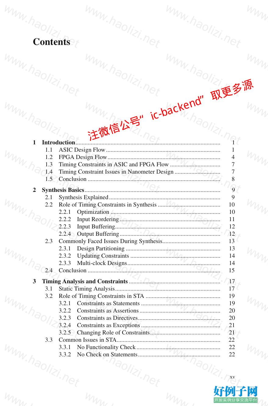
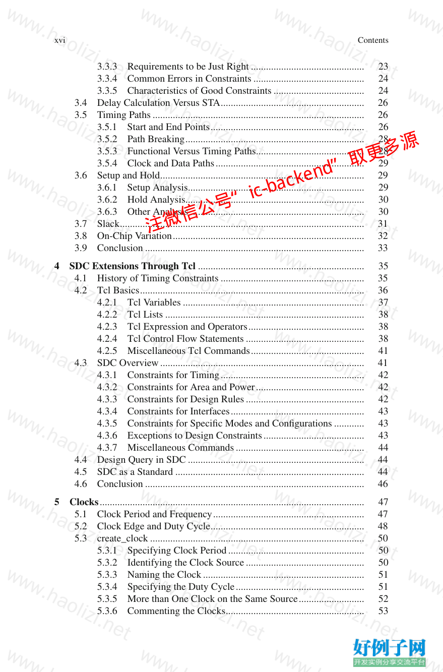
Contents
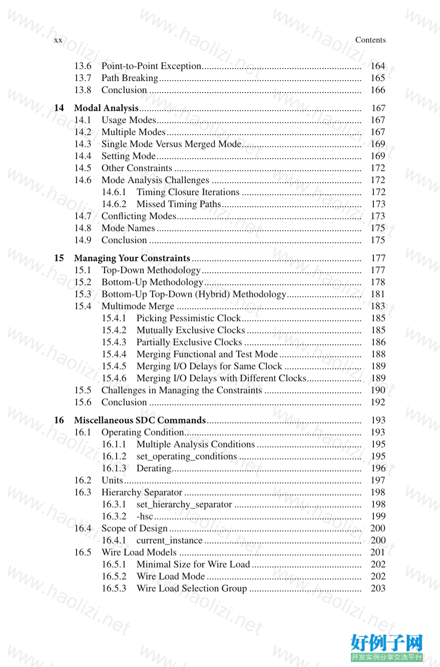
1 Introduction ............................................................................................... 1
1.1 ASIC Design Flow ........................................................................... 1
1.2 FPGA Design Flow .......................................................................... 4
1.3 Timing Constraints in ASIC and FPGA Flow ................................. 7
1.4 Timing Constraint Issues in Nanometer Design .............................. 7
1.5 Conclusion ....................................................................................... 8
2 Synthesis Basics ......................................................................................... 9
2.1 Synthesis Explained ......................................................................... 9
2.2 Role of Timing Constraints in Synthesis ......................................... 10
2.2.1 Optimization ........................................................................ 10
2.2.2 Input Reordering .................................................................. 11
2.2.3 Input Buffering ..................................................................... 12
2.2.4 Output Buffering .................................................................. 12
2.3 Commonly Faced Issues During Synthesis ...................................... 13
2.3.1 Design Partitioning .............................................................. 13
2.3.2 Updating Constraints ........................................................... 14
2.3.3 Multi-clock Designs ............................................................. 14
2.4 Conclusion ....................................................................................... 15
3 Timing Analysis and Constraints ............................................................ 17
3.1 Static Timing Analysis ..................................................................... 17
3.2 Role of Timing Constraints in STA ................................................. 19
3.2.1 Constraints as Statements .................................................... 19
3.2.2 Constraints as Assertions ..................................................... 20
3.2.3 Constraints as Directives ...................................................... 20
3.2.4 Constraints as Exceptions .................................................... 21
3.2.5 Changing Role of Constraints .............................................. 21
3.3 Common Issues in STA .................................................................... 22
3.3.1 No Functionality Check ....................................................... 22
3.3.2 No Check on Statements ...................................................... 22
注微信公号“ic-backend”取更多源
xvi
3.3.3 Requirements to be Just Right ............................................. 23
3.3.4 Common Errors in Constraints ............................................ 24
3.3.5 Characteristics of Good Constraints .................................... 24
3.4 Delay Calculation Versus STA ......................................................... 26
3.5 Timing Paths .................................................................................... 26
3.5.1 Start and End Points ............................................................. 26
3.5.2 Path Breaking ....................................................................... 28
3.5.3 Functional Versus Timing Paths........................................... 28
3.5.4 Clock and Data Paths ........................................................... 29
3.6 Setup and Hold ................................................................................. 29
3.6.1 Setup Analysis...................................................................... 29
3.6.2 Hold Analysis ....................................................................... 30
3.6.3 Other Analysis ..................................................................... 30
3.7 Slack ................................................................................................. 31
3.8 On-Chip Variation ............................................................................ 32
3.9 Conclusion ....................................................................................... 33
4 SDC Extensions Through Tcl .................................................................. 35
4.1 History of Timing Constraints ......................................................... 35
4.2 Tcl Basics ......................................................................................... 36
4.2.1 Tcl Variables ........................................................................ 37
4.2.2 Tcl Lists ............................................................................... 38
4.2.3 Tcl Expression and Operators .............................................. 38
4.2.4 Tcl Control Flow Statements ............................................... 38
4.2.5 Miscellaneous Tcl Commands ............................................. 41
4.3 SDC Overview ................................................................................. 41
4.3.1 Constraints for Timing ......................................................... 42
4.3.2 Constraints for Area and Power ........................................... 42
4.3.3 Constraints for Design Rules ............................................... 42
4.3.4 Constraints for Interfaces ..................................................... 43
4.3.5 Constraints for Specifi c Modes and Confi gurations ............ 43
4.3.6 Exceptions to Design Constraints ........................................ 43
4.3.7 Miscellaneous Commands ................................................... 44
4.4 Design Query in SDC ...................................................................... 44
4.5 SDC as a Standard ........................................................................... 44
4.6 Conclusion ....................................................................................... 46
5 Clocks ......................................................................................................... 47
5.1 Clock Period and Frequency ............................................................ 47
5.2 Clock Edge and Duty Cycle ............................................................. 48
5.3 create_clock ..................................................................................... 50
5.3.1 Specifying Clock Period ...................................................... 50
5.3.2 Identifying the Clock Source ............................................... 50
5.3.3 Naming the Clock ................................................................ 51
5.3.4 Specifying the Duty Cycle ................................................... 51
5.3.5 More than One Clock on the Same Source .......................... 52
5.3.6 Commenting the Clocks ....................................................... 53
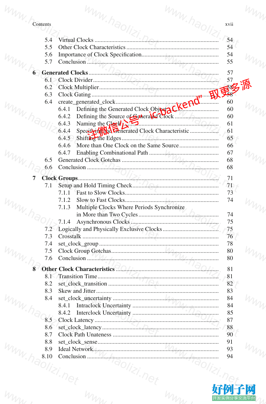
Contents
注微信公号“ic-backend”取更多源
xvii
5.4 Virtual Clocks .................................................................................. 54
5.5 Other Clock Characteristics ............................................................. 54
5.6 Importance of Clock Specifi cation ................................................... 54
5.7 Conclusion ....................................................................................... 55
6 Generated Clocks ...................................................................................... 57
6.1 Clock Divider ................................................................................... 57
6.2 Clock Multiplier ............................................................................... 58
6.3 Clock Gating .................................................................................... 58
6.4 create_generated_clock .................................................................... 60
6.4.1 Defi ning the Generated Clock Object .................................. 60
6.4.2 Defi ning the Source of Generated Clock ............................. 60
6.4.3 Naming the Clock ................................................................ 61
6.4.4 Specifying the Generated Clock Characteristic ................... 61
6.4.5 Shifting the Edges ................................................................ 65
6.4.6 More than One Clock on the Same Source .......................... 66
6.4.7 Enabling Combinational Path .............................................. 67
6.5 Generated Clock Gotchas ................................................................ 68
6.6 Conclusion ....................................................................................... 68
7 Clock Groups ............................................................................................. 71
7.1 Setup and Hold Timing Check ......................................................... 71
7.1.1 Fast to Slow Clocks .............................................................. 73
7.1.2 Slow to Fast Clocks .............................................................. 74
7.1.3 Multiple Clocks Where Periods Synchronize
in More than Two Cycles ..................................................... 74
7.1.4 Asynchronous Clocks .......................................................... 75
7.2 Logically and Physically Exclusive Clocks ..................................... 75
7.3 Crosstalk .......................................................................................... 76
7.4 set_clock_group ............................................................................... 78
7.5 Clock Group Gotchas ....................................................................... 80
7.6 Conclusion ....................................................................................... 80
8 Other Clock Characteristics .................................................................... 81
8.1 Transition Time ................................................................................ 81
8.2 set_clock_transition ......................................................................... 82
8.3 Skew and Jitter ................................................................................. 83
8.4 set_clock_uncertainty ...................................................................... 84
8.4.1 Intraclock Uncertainty ......................................................... 84
8.4.2 Interclock Uncertainty ......................................................... 85
8.5 Clock Latency .................................................................................. 87
8.6 set_clock_latency ............................................................................. 88
8.7 Clock Path Unateness ...................................................................... 90
8.8 set_clock_sense ................................................................................ 91
8.9 Ideal Network ................................................................................... 93
8.10 Conclusion ....................................................................................... 94
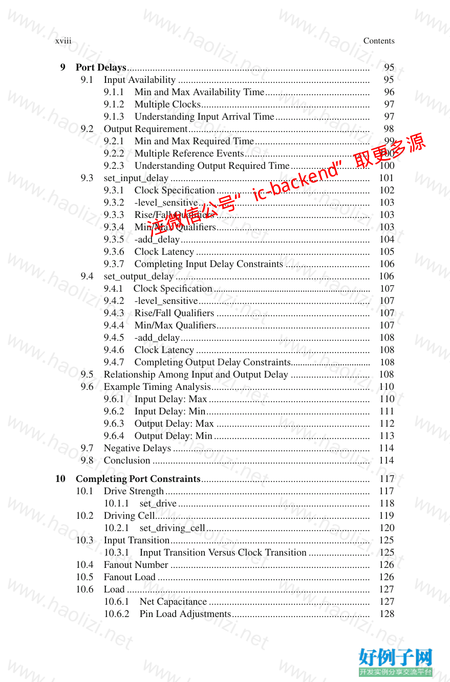
Contents
注微信公号“ic-backend”取更多源
xviii
9 Port Delays ............................................................................................... 95
9.1 Input Availability ........................................................................... 95
9.1.1 Min and Max Availability Time ......................................... 96
9.1.2 Multiple Clocks .................................................................. 97
9.1.3 Understanding Input Arrival Time ..................................... 97
9.2 Output Requirement ....................................................................... 98
9.2.1 Min and Max Required Time ............................................. 99
9.2.2 Multiple Reference Events ................................................. 100
9.2.3 Understanding Output Required Time ............................... 100
9.3 set_input_delay .............................................................................. 101
9.3.1 Clock Specifi cation ............................................................ 102
9.3.2 -level_sensitive ................................................................... 103
9.3.3 Rise/Fall Qualifi ers ............................................................ 103
9.3.4 Min/Max Qualifi ers ............................................................ 103
9.3.5 -add_delay .......................................................................... 104
9.3.6 Clock Latency .................................................................... 105
9.3.7 Completing Input Delay Constraints ................................. 106
9.4 set_output_delay ............................................................................ 106
9.4.1 Clock Specifi cation ................................................................... 107
9.4.2 -level_sensitive ................................................................... 107
9.4.3 Rise/Fall Qualifi ers ............................................................ 107
9.4.4 Min/Max Qualifi ers ............................................................ 107
9.4.5 -add_delay .......................................................................... 108
9.4.6 Clock Latency .................................................................... 108
9.4.7 Completing Output Delay Constraints .................................. 108
9.5 Relationship Among Input and Output Delay ............................... 108
9.6 Example Timing Analysis .............................................................. 110
9.6.1 Input Delay: Max ............................................................... 110
9.6.2 Input Delay: Min ................................................................ 111
9.6.3 Output Delay: Max ............................................................ 112
9.6.4 Output Delay: Min ............................................................. 113
9.7 Negative Delays ............................................................................. 114
9.8 Conclusion ..................................................................................... 114
10 Completing Port Constraints .................................................................. 117
10.1 Drive Strength ................................................................................ 117
10.1.1 set_drive ........................................................................... 118
10.2 Driving Cell.................................................................................... 119
10.2.1 set_driving_cell ................................................................ 120
10.3 Input Transition .............................................................................. 125
10.3.1 Input Transition Versus Clock Transition ........................ 125
10.4 Fanout Number .............................................................................. 126
10.5 Fanout Load ................................................................................... 126
10.6 Load ............................................................................................... 127
10.6.1 Net Capacitance ............................................................... 127
10.6.2 Pin Load Adjustments ...................................................... 128
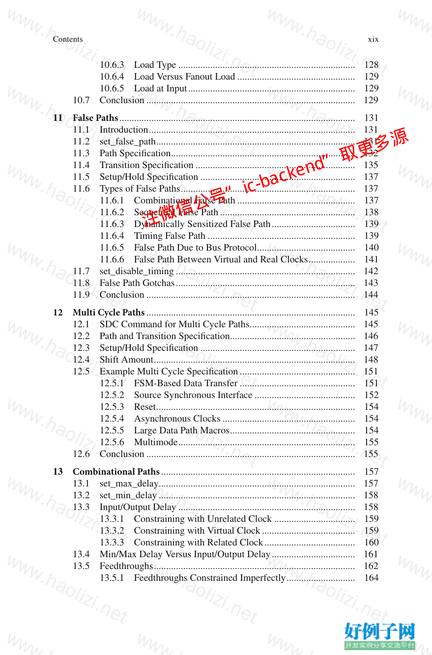
Contents
注微信公号“ic-backend”取更多源
xix
10.6.3 Load Type ........................................................................ 128
10.6.4 Load Versus Fanout Load ................................................ 129
10.6.5 Load at Input .................................................................... 129
10.7 Conclusion ..................................................................................... 129
11 False Paths ................................................................................................ 131
11.1 Introduction .................................................................................... 131
11.2 set_false_path ................................................................................. 131
11.3 Path Specifi cation ........................................................................... 132
11.4 Transition Specifi cation ................................................................. 135
11.5 Setup/Hold Specifi cation ............................................................... 137
11.6 Types of False Paths ....................................................................... 137
11.6.1 Combinational False Path ................................................ 137
11.6.2 Sequential False Path ....................................................... 138
11.6.3 Dynamically Sensitized False Path .................................. 139
11.6.4 Timing False Path ............................................................ 139
11.6.5 False Path Due to Bus Protocol ........................................ 140
11.6.6 False Path Between Virtual and Real Clocks ................... 141
11.7 set_disable_timing ......................................................................... 142
11.8 False Path Gotchas ......................................................................... 143
11.9 Conclusion ..................................................................................... 144
12 Multi Cycle Paths ..................................................................................... 145
12.1 SDC Command for Multi Cycle Paths ........................................... 145
12.2 Path and Transition Specifi cation................................................... 146
12.3 Setup/Hold Specifi cation ............................................................... 147
12.4 Shift Amount .................................................................................. 148
12.5 Example Multi Cycle Specifi cation ............................................... 151
12.5.1 FSM-Based Data Transfer ............................................... 151
12.5.2 Source Synchronous Interface ......................................... 152
12.5.3 Reset ................................................................................. 154
12.5.4 Asynchronous Clocks ...................................................... 154
12.5.5 Large Data Path Macros ................................................... 154
12.5.6 Multimode ........................................................................ 155
12.6 Conclusion ..................................................................................... 155
13 Combinational Paths ............................................................................... 157
13.1 set_max_delay ................................................................................ 157
13.2 set_min_delay ................................................................................ 158
13.3 Input/Output Delay ........................................................................ 158
13.3.1 Constraining with Unrelated Clock ................................. 159
13.3.2 Constraining with Virtual Clock ...................................... 159
13.3.3 Constraining with Related Clock ..................................... 160
13.4 Min/Max Delay Versus Input/Output Delay .................................. 161
13.5 Feedthroughs .................................................................................. 162
13.5.1 Feedthroughs Constrained Imperfectly ............................ 164
Contents
注微信公号“ic-backend”取更多源
xx
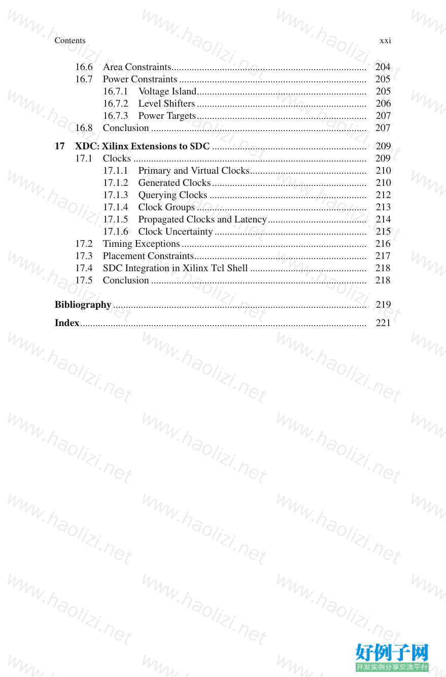
13.6 Point-to-Point Exception ................................................................ 164
13.7 Path Breaking ................................................................................. 165
13.8 Conclusion ..................................................................................... 166
14 Modal Analysis ......................................................................................... 167
14.1 Usage Modes .................................................................................. 167
14.2 Multiple Modes .............................................................................. 167
14.3 Single Mode Versus Merged Mode ................................................ 169
14.4 Setting Mode .................................................................................. 169
14.5 Other Constraints ........................................................................... 172
14.6 Mode Analysis Challenges ............................................................ 172
14.6.1 Timing Closure Iterations ................................................ 172
14.6.2 Missed Timing Paths ........................................................ 173
14.7 Confl icting Modes .......................................................................... 173
14.8 Mode Names .................................................................................. 175
14.9 Conclusion ..................................................................................... 175
15 Managing Your Constraints .................................................................... 177
15.1 Top-Down Methodology ................................................................ 177
15.2 Bottom-Up Methodology ............................................................... 178
15.3 Bottom-Up Top-Down (Hybrid) Methodology .............................. 181
15.4 Multimode Merge .......................................................................... 183
15.4.1 Picking Pessimistic Clock ................................................ 185
15.4.2 Mutually Exclusive Clocks .............................................. 185
15.4.3 Partially Exclusive Clocks ............................................... 186
15.4.4 Merging Functional and Test Mode ................................. 188
15.4.5 Merging I/O Delays for Same Clock ............................... 189
15.4.6 Merging I/O Delays with Different Clocks ...................... 189
15.5 Challenges in Managing the Constraints ....................................... 190
15.6 Conclusion ..................................................................................... 192
16 Miscellaneous SDC Commands .............................................................. 193
16.1 Operating Condition ....................................................................... 193
16.1.1 Multiple Analysis Conditions .......................................... 195
16.1.2 set_operating_conditions ................................................. 195
16.1.3 Derating ............................................................................ 196
16.2 Units ............................................................................................... 197
16.3 Hierarchy Separator ....................................................................... 198
16.3.1 set_hierarchy_separator ................................................... 198
16.3.2 -hsc ................................................................................... 199
16.4 Scope of Design ............................................................................. 200
16.4.1 current_instance ............................................................... 200
16.5 Wire Load Models ......................................................................... 201
16.5.1 Minimal Size for Wire Load ............................................ 202
16.5.2 Wire Load Mode .............................................................. 202
16.5.3 Wire Load Selection Group ............................................. 203
Contents
xxi
16.6 Area Constraints ............................................................................. 204
16.7 Power Constraints .......................................................................... 205
16.7.1 Voltage Island ................................................................... 205
16.7.2 Level Shifters ................................................................... 206
16.7.3 Power Targets ................................................................... 207
16.8 Conclusion ..................................................................................... 207
17 XDC: Xilinx Extensions to SDC ............................................................. 209
17.1 Clocks ............................................................................................ 209
17.1.1 Primary and Virtual Clocks .............................................. 210
17.1.2 Generated Clocks ............................................................. 210
17.1.3 Querying Clocks .............................................................. 212
17.1.4 Clock Groups ................................................................... 213
17.1.5 Propagated Clocks and Latency ....................................... 214
17.1.6 Clock Uncertainty ............................................................ 215
17.2 Timing Exceptions ......................................................................... 216
17.3 Placement Constraints .................................................................... 217
17.4 SDC Integration in Xilinx Tcl Shell .............................................. 218
17.5 Conclusion ..................................................................................... 218
Bibliography .................................................................................................... 219
Index ................................................................................................................. 221
Contents
xxiii
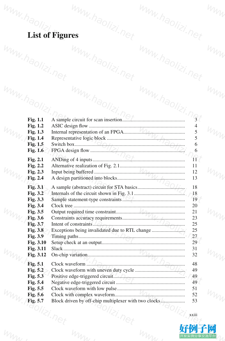
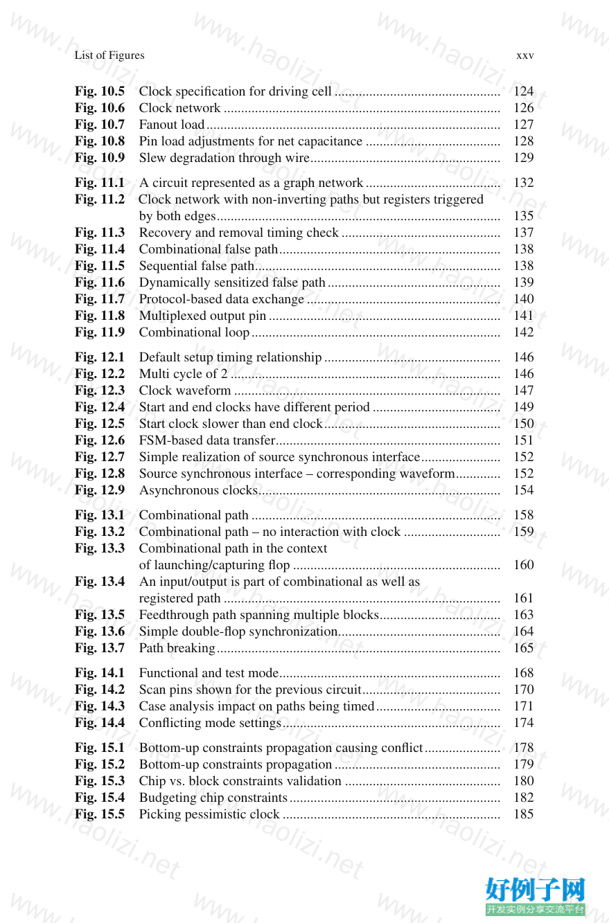
Fig. 1.1 A sample circuit for scan insertion ................................................. 3
Fig. 1.2 ASIC design fl ow ........................................................................... 4
Fig. 1.3 Internal representation of an FPGA................................................ 5
Fig. 1.4 Representative logic block ............................................................. 5
Fig. 1.5 Switch box ...................................................................................... 6
Fig. 1.6 FPGA design fl ow .......................................................................... 6
Fig. 2.1 ANDing of 4 inputs ........................................................................ 11
Fig. 2.2 Alternative realization of Fig. 2.1 ................................................... 11
Fig. 2.3 Input being buffered ....................................................................... 12
Fig. 2.4 A design partitioned into blocks ..................................................... 13
Fig. 3.1 A sample (abstract) circuit for STA basics ..................................... 18
Fig. 3.2 Internals of the circuit shown in Fig. 3.1 ........................................ 18
Fig. 3.3 Sample statement- type constraints ................................................. 19
Fig. 3.4 Clock tree ....................................................................................... 20
Fig. 3.5 Output required time constraint ...................................................... 21
Fig. 3.6 Constraints accuracy requirements ................................................. 23
Fig. 3.7 Intent of constraints ........................................................................ 25
Fig. 3.8 Exceptions being invalidated due to RTL change .......................... 25
Fig. 3.9 Timing paths ................................................................................... 27
Fig. 3.10 Setup check at an output ................................................................. 29
Fig. 3.11 Slack ............................................................................................... 31
Fig. 3.12 On-chip variation ............................................................................ 32
Fig. 5.1 Clock waveform ............................................................................. 48
Fig. 5.2 Clock waveform with uneven duty cycle ....................................... 49
Fig. 5.3 Positive edge- triggered circuit ........................................................ 49
Fig. 5.4 Negative edge-triggered circuit ...................................................... 49
Fig. 5.5 Clock waveform with low pulse ..................................................... 51
Fig. 5.6 Clock with complex waveform....................................................... 52
Fig. 5.7 Block driven by off-chip multiplexer with two clocks ................... 53
List of Figures
xxiv
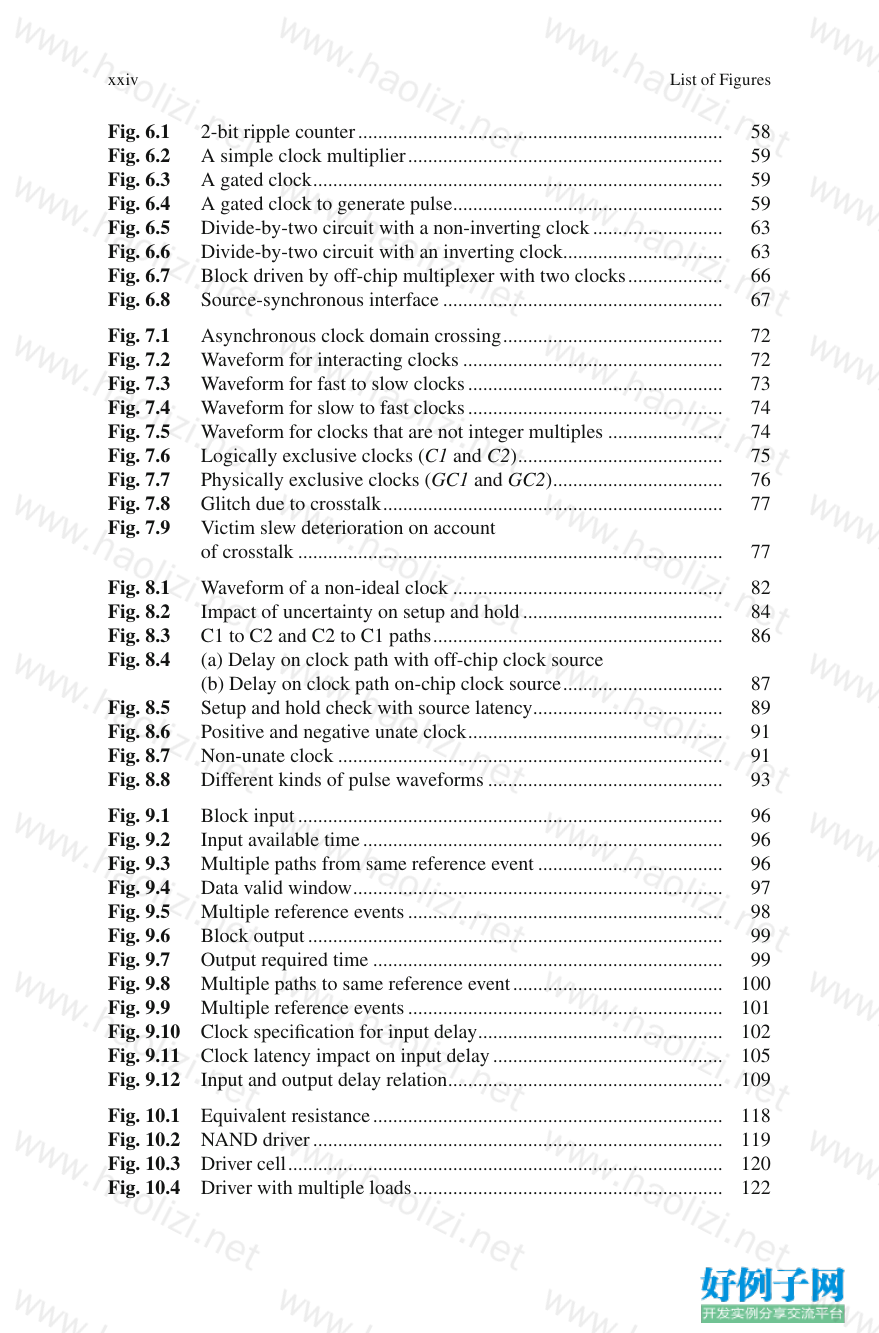
Fig. 6.1 2-bit ripple counter ......................................................................... 58
Fig. 6.2 A simple clock multiplier ............................................................... 59
Fig. 6.3 A gated clock .................................................................................. 59
Fig. 6.4 A gated clock to generate pulse ...................................................... 59
Fig. 6.5 Divide-by-two circuit with a non-inverting clock .......................... 63
Fig. 6.6 Divide-by-two circuit with an inverting clock................................ 63
Fig. 6.7 Block driven by off-chip multiplexer with two clocks ................... 66
Fig. 6.8 Source-synchronous interface ........................................................ 67
Fig. 7.1 Asynchronous clock domain crossing ............................................ 72
Fig. 7.2 Waveform for interacting clocks .................................................... 72
Fig. 7.3 Waveform for fast to slow clocks ................................................... 73
Fig. 7.4 Waveform for slow to fast clocks ................................................... 74
Fig. 7.5 Waveform for clocks that are not integer multiples ....................... 74
Fig. 7.6 Logically exclusive clocks (C1 and C2) ......................................... 75
Fig. 7.7 Physically exclusive clocks (GC1 and GC2) .................................. 76
Fig. 7.8 Glitch due to crosstalk .................................................................... 77
Fig. 7.9 Victim slew deterioration on account
of crosstalk ..................................................................................... 77
Fig. 8.1 Waveform of a non-ideal clock ...................................................... 82
Fig. 8.2 Impact of uncertainty on setup and hold ........................................ 84
Fig. 8.3 C1 to C2 and C2 to C1 paths .......................................................... 86
Fig. 8.4 (a) Delay on clock path with off-chip clock source
(b) Delay on clock path on-chip clock source ................................ 87
Fig. 8.5 Setup and hold check with source latency ...................................... 89
Fig. 8.6 Positive and negative unate clock ................................................... 91
Fig. 8.7 Non-unate clock ............................................................................. 91
Fig. 8.8 Different kinds of pulse waveforms ............................................... 93
Fig. 9.1 Block input ..................................................................................... 96
Fig. 9.2 Input available time ........................................................................ 96
Fig. 9.3 Multiple paths from same reference event ..................................... 96
Fig. 9.4 Data valid window .......................................................................... 97
Fig. 9.5 Multiple reference events ............................................................... 98
Fig. 9.6 Block output ................................................................................... 99
Fig. 9.7 Output required time ...................................................................... 99
Fig. 9.8 Multiple paths to same reference event .......................................... 100
Fig. 9.9 Multiple reference events ............................................................... 101
Fig. 9.10 Clock specifi cation for input delay ................................................. 102
Fig. 9.11 Clock latency impact on input delay .............................................. 105
Fig. 9.12 Input and output delay relation ....................................................... 109
Fig. 10.1 Equivalent resistance ...................................................................... 118
Fig. 10.2 NAND driver .................................................................................. 119
Fig. 10.3 Driver cell ....................................................................................... 120
Fig. 10.4 Driver with multiple loads .............................................................. 122
List of Figures
xxv
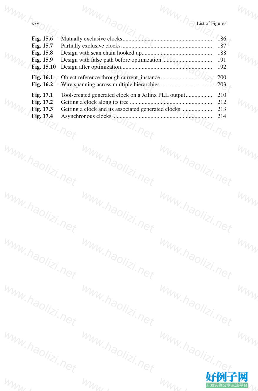
Fig. 10.5 Clock specifi cation for driving cell ................................................ 124
Fig. 10.6 Clock network ................................................................................ 126
Fig. 10.7 Fanout load ..................................................................................... 127
Fig. 10.8 Pin load adjustments for net capacitance ....................................... 128
Fig. 10.9 Slew degradation through wire ....................................................... 129
Fig. 11.1 A circuit represented as a graph network ....................................... 132
Fig. 11.2 Clock network with non-inverting paths but registers triggered
by both edges .................................................................................. 135
Fig. 11.3 Recovery and removal timing check .............................................. 137
Fig. 11.4 Combinational false path ................................................................ 138
Fig. 11.5 Sequential false path ....................................................................... 138
Fig. 11.6 Dynamically sensitized false path .................................................. 139
Fig. 11.7 Protocol-based data exchange ........................................................ 140
Fig. 11.8 Multiplexed output pin ................................................................... 141
Fig. 11.9 Combinational loop ........................................................................ 142
Fig. 12.1 Default setup timing relationship ................................................... 146
Fig. 12.2 Multi cycle of 2 .............................................................................. 146
Fig. 12.3 Clock waveform ............................................................................. 147
Fig. 12.4 Start and end clocks have different period ..................................... 149
Fig. 12.5 Start clock slower than end clock ................................................... 150
Fig. 12.6 FSM-based data transfer ................................................................. 151
Fig. 12.7 Simple realization of source synchronous interface ....................... 152
Fig. 12.8 Source synchronous interface – corresponding waveform ............. 152
Fig. 12.9 Asynchronous clocks ...................................................................... 154
Fig. 13.1 Combinational path ........................................................................ 158
Fig. 13.2 Combinational path – no interaction with clock ............................ 159
Fig. 13.3 Combinational path in the context
of launching/capturing fl op ............................................................ 160
Fig. 13.4 An input/output is part of combinational as well as
registered path ................................................................................ 161
Fig. 13.5 Feedthrough path spanning multiple blocks ................................... 163
Fig. 13.6 Simple double-fl op synchronization ............................................... 164
Fig. 13.7 Path breaking .................................................................................. 165
Fig. 14.1 Functional and test mode ................................................................ 168
Fig. 14.2 Scan pins shown for the previous circuit ........................................ 170
Fig. 14.3 Case analysis impact on paths being timed .................................... 171
Fig. 14.4 Confl icting mode settings ............................................................... 174
Fig. 15.1 Bottom-up constraints propagation causing confl ict ...................... 178
Fig. 15.2 Bottom-up constraints propagation ................................................ 179
Fig. 15.3 Chip vs. block constraints validation ............................................. 180
Fig. 15.4 Budgeting chip constraints ............................................................. 182
Fig. 15.5 Picking pessimistic clock ............................................................... 185
List of Figures
xxvi
Fig. 15.6 Mutually exclusive clocks ............................................................. 186
Fig. 15.7 Partially exclusive clocks .............................................................. 187
Fig. 15.8 Design with scan chain hooked up ................................................ 188
Fig. 15.9 Design with false path before optimization .................................. 191
Fig. 15.10 Design after optimization .............................................................. 192
Fig. 16.1 Object reference through current_instance ................................... 200
Fig. 16.2 Wire spanning across multiple hierarchies ................................... 203
Fig. 17.1 Tool-created generated clock on a Xilinx PLL output .................. 210
Fig. 17.2 Getting a clock along its tree ........................................................ 212
Fig. 17.3 Getting a clock and its associated generated clocks ..................... 213
Fig. 17.4 Asynchronous clocks .................................................................... 214
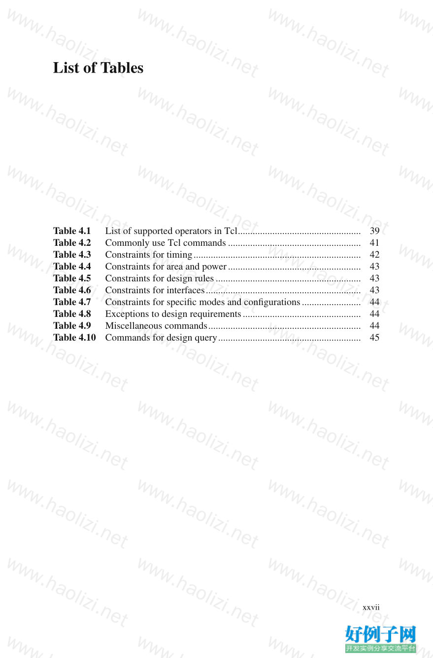
List of Figures
xxvii
Table 4.1 List of supported operators in Tcl .................................................. 39
Table 4.2 Commonly use Tcl commands ...................................................... 41
Table 4.3 Constraints for timing .................................................................... 42
Table 4.4 Constraints for area and power ...................................................... 43
Table 4.5 Constraints for design rules ........................................................... 43
Table 4.6 Constraints for interfaces ............................................................... 43
Table 4.7 Constraints for specifi c modes and confi gurations ........................ 44
Table 4.8 Exceptions to design requirements ................................................ 44
Table 4.9 Miscellaneous commands .............................................................. 44
Table 4.10 Commands for design query .......................................................... 45
小贴士
感谢您为本站写下的评论,您的评论对其它用户来说具有重要的参考价值,所以请认真填写。
- 类似“顶”、“沙发”之类没有营养的文字,对勤劳贡献的楼主来说是令人沮丧的反馈信息。
- 相信您也不想看到一排文字/表情墙,所以请不要反馈意义不大的重复字符,也请尽量不要纯表情的回复。
- 提问之前请再仔细看一遍楼主的说明,或许是您遗漏了。
- 请勿到处挖坑绊人、招贴广告。既占空间让人厌烦,又没人会搭理,于人于己都无利。
关于好例子网
本站旨在为广大IT学习爱好者提供一个非营利性互相学习交流分享平台。本站所有资源都可以被免费获取学习研究。本站资源来自网友分享,对搜索内容的合法性不具有预见性、识别性、控制性,仅供学习研究,请务必在下载后24小时内给予删除,不得用于其他任何用途,否则后果自负。基于互联网的特殊性,平台无法对用户传输的作品、信息、内容的权属或合法性、安全性、合规性、真实性、科学性、完整权、有效性等进行实质审查;无论平台是否已进行审查,用户均应自行承担因其传输的作品、信息、内容而可能或已经产生的侵权或权属纠纷等法律责任。本站所有资源不代表本站的观点或立场,基于网友分享,根据中国法律《信息网络传播权保护条例》第二十二与二十三条之规定,若资源存在侵权或相关问题请联系本站客服人员,点此联系我们。关于更多版权及免责申明参见 版权及免责申明


网友评论
我要评论