实例介绍
【实例简介】最新的视频编解码H.266标准文档
【实例截图】




【核心代码】
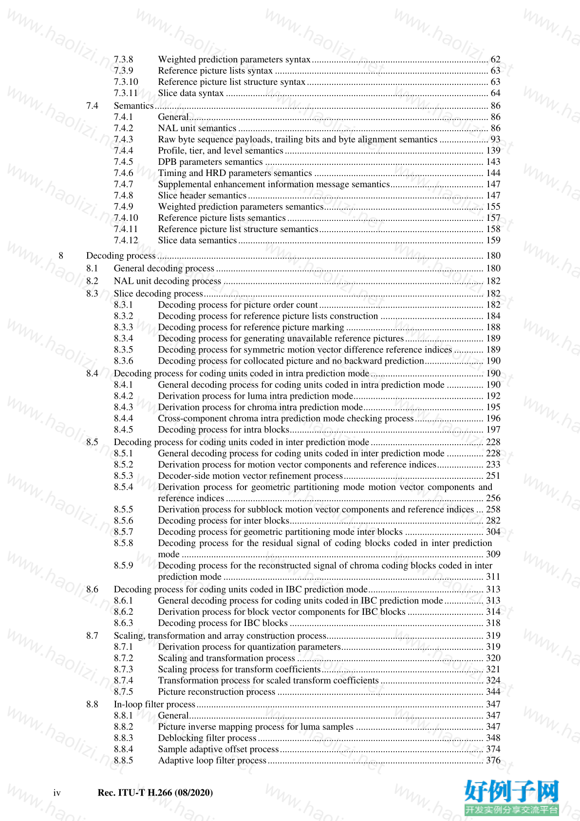
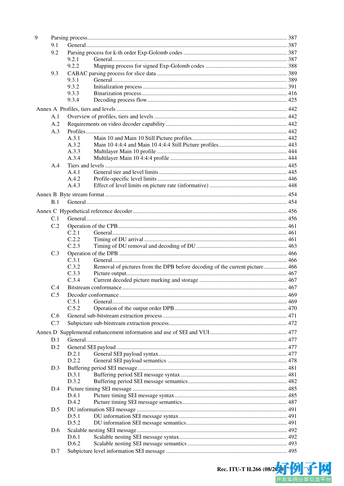
CONTENTS
PageIntroduction ............................................................................................................................................................. 1
Purpose ......................................................................................................................................................... 1
Profiles, tiers, and levels .............................................................................................................................. 1
Encoding process, decoding process, and use of VUI parameters and SEI messages .................................. 1
Versions of this Recommendation | International Standard ......................................................................... 2
Overview of the design characteristics ......................................................................................................... 2
How to read this document .......................................................................................................................... 2
1 Scope ............................................................................................................................................................ 2
2 Normative references ................................................................................................................................... 3
2.1 Identical Recommendations | International Standards ...................................................................... 3
2.2 Paired Recommendations | International Standards equivalent in technical content ........................ 3
2.3 Additional references ........................................................................................................................ 3
3 Definitions .................................................................................................................................................... 3
4 Abbreviations ............................................................................................................................................. 11
5 Conventions ............................................................................................................................................... 13
5.1 General ............................................................................................................................................ 13
5.2 Arithmetic operators ....................................................................................................................... 13
5.3 Logical operators ............................................................................................................................ 14
5.4 Relational operators ........................................................................................................................ 14
5.5 Bit-wise operators ........................................................................................................................... 14
5.6 Assignment operators ..................................................................................................................... 14
5.7 Range notation ................................................................................................................................ 15
5.8 Mathematical functions ................................................................................................................... 15
5.9 Order of operation precedence ........................................................................................................ 15
5.10 Variables, syntax elements and tables ............................................................................................. 16
5.11 Text description of logical operations ............................................................................................. 17
5.12 Processes ......................................................................................................................................... 18
6 Bitstream and picture formats, partitionings, scanning processes and neighbouring relationships ............ 19
6.1 Bitstream formats ............................................................................................................................ 19
6.2 Source, decoded and output picture formats ................................................................................... 19
6.3 Partitioning of pictures, subpictures, slices, tiles, and CTUs .......................................................... 21
6.3.1 Partitioning of pictures into subpictures, slices, and tiles ............................................. 21
6.3.2 Block, quadtree and multi-type tree structures ............................................................. 23
6.3.3 Spatial or component-wise partitionings ....................................................................... 23
6.4 Availability processes ..................................................................................................................... 24
6.4.1 Allowed quad split process ........................................................................................... 24
6.4.2 Allowed binary split process ......................................................................................... 25
6.4.3 Allowed ternary split process ........................................................................................ 26
6.4.4 Derivation process for neighbouring block availability ................................................ 27
6.5 Scanning processes ......................................................................................................................... 28
6.5.1 CTB raster scanning, tile scanning, and subpicture scanning processes ....................... 28
6.5.2 Up-right diagonal scan order array initialization process ............................................. 32
6.5.3 Horizontal and vertical traverse scan order array initialization process........................ 32
7 Syntax and semantics ................................................................................................................................. 33
7.1 Method of specifying syntax in tabular form .................................................................................. 33
7.2 Specification of syntax functions and descriptors ........................................................................... 34
7.3 Syntax in tabular form .................................................................................................................... 35
7.3.1 NAL unit syntax ........................................................................................................... 35
7.3.2 Raw byte sequence payloads, trailing bits and byte alignment syntax.......................... 36
7.3.3 Profile, tier, and level syntax ........................................................................................ 55
7.3.4 DPB parameters syntax ................................................................................................. 57
7.3.5 Timing and HRD parameters syntax ............................................................................. 58
7.3.6 Supplemental enhancement information message syntax ............................................. 59
7.3.7 Slice header syntax ....................................................................................................... 59
iv Rec. ITU-T H.266 (08/2020)
7.3.8 Weighted prediction parameters syntax ........................................................................ 62
7.3.9 Reference picture lists syntax ....................................................................................... 63
7.3.10 Reference picture list structure syntax .......................................................................... 63
7.3.11 Slice data syntax ........................................................................................................... 64
7.4 Semantics ........................................................................................................................................ 86
7.4.1 General .......................................................................................................................... 86
7.4.2 NAL unit semantics ...................................................................................................... 86
7.4.3 Raw byte sequence payloads, trailing bits and byte alignment semantics .................... 93
7.4.4 Profile, tier, and level semantics ................................................................................. 139
7.4.5 DPB parameters semantics ......................................................................................... 143
7.4.6 Timing and HRD parameters semantics ..................................................................... 144
7.4.7 Supplemental enhancement information message semantics ...................................... 147
7.4.8 Slice header semantics ................................................................................................ 147
7.4.9 Weighted prediction parameters semantics ................................................................. 155
7.4.10 Reference picture lists semantics ................................................................................ 157
7.4.11 Reference picture list structure semantics ................................................................... 158
7.4.12 Slice data semantics .................................................................................................... 159
8 Decoding process ..................................................................................................................................... 180
8.1 General decoding process ............................................................................................................. 180
8.2 NAL unit decoding process .......................................................................................................... 182
8.3 Slice decoding process .................................................................................................................. 182
8.3.1 Decoding process for picture order count ................................................................... 182
8.3.2 Decoding process for reference picture lists construction .......................................... 184
8.3.3 Decoding process for reference picture marking ........................................................ 188
8.3.4 Decoding process for generating unavailable reference pictures ................................ 189
8.3.5 Decoding process for symmetric motion vector difference reference indices ............ 189
8.3.6 Decoding process for collocated picture and no backward prediction ........................ 190
8.4 Decoding process for coding units coded in intra prediction mode .............................................. 190
8.4.1 General decoding process for coding units coded in intra prediction mode ............... 190
8.4.2 Derivation process for luma intra prediction mode ..................................................... 192
8.4.3 Derivation process for chroma intra prediction mode ................................................. 195
8.4.4 Cross-component chroma intra prediction mode checking process ............................ 196
8.4.5 Decoding process for intra blocks ............................................................................... 197
8.5 Decoding process for coding units coded in inter prediction mode .............................................. 228
8.5.1 General decoding process for coding units coded in inter prediction mode ............... 228
8.5.2 Derivation process for motion vector components and reference indices ................... 233
8.5.3 Decoder-side motion vector refinement process ......................................................... 251
8.5.4 Derivation process for geometric partitioning mode motion vector components and
reference indices ......................................................................................................... 256
8.5.5 Derivation process for subblock motion vector components and reference indices ... 258
8.5.6 Decoding process for inter blocks ............................................................................... 282
8.5.7 Decoding process for geometric partitioning mode inter blocks ................................ 304
8.5.8 Decoding process for the residual signal of coding blocks coded in inter prediction
mode ........................................................................................................................... 309
8.5.9 Decoding process for the reconstructed signal of chroma coding blocks coded in inter
prediction mode .......................................................................................................... 311
8.6 Decoding process for coding units coded in IBC prediction mode ............................................... 313
8.6.1 General decoding process for coding units coded in IBC prediction mode ................ 313
8.6.2 Derivation process for block vector components for IBC blocks ............................... 314
8.6.3 Decoding process for IBC blocks ............................................................................... 318
8.7 Scaling, transformation and array construction process ................................................................ 319
8.7.1 Derivation process for quantization parameters .......................................................... 319
8.7.2 Scaling and transformation process ............................................................................ 320
8.7.3 Scaling process for transform coefficients .................................................................. 321
8.7.4 Transformation process for scaled transform coefficients .......................................... 324
8.7.5 Picture reconstruction process .................................................................................... 344
8.8 In-loop filter process ..................................................................................................................... 347
8.8.1 General ........................................................................................................................ 347
8.8.2 Picture inverse mapping process for luma samples .................................................... 347
8.8.3 Deblocking filter process ............................................................................................ 348
8.8.4 Sample adaptive offset process ................................................................................... 374
8.8.5 Adaptive loop filter process ........................................................................................ 376
Rec. ITU-T H.266 (08/2020) v
9 Parsing process ......................................................................................................................................... 387
9.1 General .......................................................................................................................................... 387
9.2 Parsing process for k-th order Exp-Golomb codes ....................................................................... 387
9.2.1 General ........................................................................................................................ 387
9.2.2 Mapping process for signed Exp-Golomb codes ........................................................ 388
9.3 CABAC parsing process for slice data ......................................................................................... 389
9.3.1 General ........................................................................................................................ 389
9.3.2 Initialization process ................................................................................................... 391
9.3.3 Binarization process .................................................................................................... 416
9.3.4 Decoding process flow ................................................................................................ 425
Annex A Profiles, tiers and levels ..................................................................................................................... 442
A.1 Overview of profiles, tiers and levels ........................................................................................... 442
A.2 Requirements on video decoder capability ................................................................................... 442
A.3 Profiles .......................................................................................................................................... 442
A.3.1 Main 10 and Main 10 Still Picture profiles ................................................................. 442
A.3.2 Main 10 4:4:4 and Main 10 4:4:4 Still Picture profiles............................................... 443
A.3.3 Multilayer Main 10 profile ......................................................................................... 444
A.3.4 Multilayer Main 10 4:4:4 profile ................................................................................ 444
A.4 Tiers and levels ............................................................................................................................. 445
A.4.1 General tier and level limits ........................................................................................ 445
A.4.2 Profile-specific level limits ......................................................................................... 446
A.4.3 Effect of level limits on picture rate (informative) ..................................................... 448
Annex B Byte stream format ............................................................................................................................. 454
B.1 General .......................................................................................................................................... 454
Annex C Hypothetical reference decoder .......................................................................................................... 456
C.1 General .......................................................................................................................................... 456
C.2 Operation of the CPB .................................................................................................................... 461
C.2.1 General ........................................................................................................................ 461
C.2.2 Timing of DU arrival .................................................................................................. 461
C.2.3 Timing of DU removal and decoding of DU .............................................................. 463
C.3 Operation of the DPB ................................................................................................................... 466
C.3.1 General ........................................................................................................................ 466
C.3.2 Removal of pictures from the DPB before decoding of the current picture ................ 466
C.3.3 Picture output .............................................................................................................. 467
C.3.4 Current decoded picture marking and storage ............................................................ 467
C.4 Bitstream conformance ................................................................................................................. 467
C.5 Decoder conformance ................................................................................................................... 469
C.5.1 General ........................................................................................................................ 469
C.5.2 Operation of the output order DPB ............................................................................. 470
C.6 General sub-bitstream extraction process ..................................................................................... 471
C.7 Subpicture sub-bitstream extraction process ................................................................................. 472
Annex D Supplemental enhancement information and use of SEI and VUI ..................................................... 477
D.1 General .......................................................................................................................................... 477
D.2 General SEI payload ..................................................................................................................... 477
D.2.1 General SEI payload syntax ........................................................................................ 477
D.2.2 General SEI payload semantics .................................................................................. 478
D.3 Buffering period SEI message ...................................................................................................... 481
D.3.1 Buffering period SEI message syntax ......................................................................... 481
D.3.2 Buffering period SEI message semantics .................................................................... 482
D.4 Picture timing SEI message .......................................................................................................... 485
D.4.1 Picture timing SEI message syntax ............................................................................. 485
D.4.2 Picture timing SEI message semantics ........................................................................ 487
D.5 DU information SEI message ....................................................................................................... 491
D.5.1 DU information SEI message syntax .......................................................................... 491
D.5.2 DU information SEI message semantics ..................................................................... 491
D.6 Scalable nesting SEI message ....................................................................................................... 492
D.6.1 Scalable nesting SEI message syntax .......................................................................... 492
D.6.2 Scalable nesting SEI message semantics .................................................................... 493
D.7 Subpicture level information SEI message ................................................................................... 495
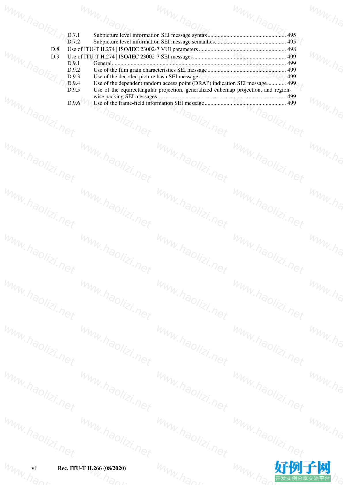
vi Rec. ITU-T H.266 (08/2020)
D.7.1 Subpicture level information SEI message syntax ...................................................... 495
D.7.2 Subpicture level information SEI message semantics ................................................. 495
D.8 Use of ITU-T H.274 | ISO/IEC 23002-7 VUI parameters ............................................................ 498
D.9 Use of ITU-T H.274 | ISO/IEC 23002-7 SEI messages ................................................................ 499
D.9.1 General ........................................................................................................................ 499
D.9.2 Use of the film grain characteristics SEI message ...................................................... 499
D.9.3 Use of the decoded picture hash SEI message ............................................................ 499
D.9.4 Use of the dependent random access point (DRAP) indication SEI message ............. 499
D.9.5 Use of the equirectangular projection, generalized cubemap projection, and region-
wise packing SEI messages ........................................................................................ 499
D.9.6 Use of the frame-field information SEI message ........................................................ 499
Rec. ITU-T H.266 (08/2020) vii
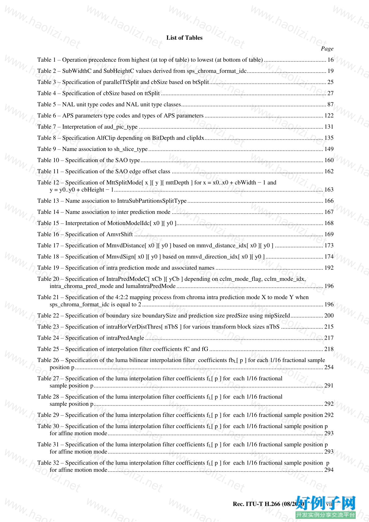
List of Tables
Page
Table 1 – Operation precedence from highest (at top of table) to lowest (at bottom of table) ........................................ 16
Table 2 – SubWidthC and SubHeightC values derived from sps_chroma_format_idc ................................................... 19
Table 3 – Specification of parallelTtSplit and cbSize based on btSplit ........................................................................... 25
Table 4 – Specification of cbSize based on ttSplit .......................................................................................................... 27
Table 5 – NAL unit type codes and NAL unit type classes ............................................................................................. 87
Table 6 – APS parameters type codes and types of APS parameters ............................................................................ 122
Table 7 – Interpretation of aud_pic_type ...................................................................................................................... 131
Table 8 – Specification AlfClip depending on BitDepth and clipIdx ............................................................................ 135
Table 9 – Name association to sh_slice_type ................................................................................................................ 149
Table 10 – Specification of the SAO type ..................................................................................................................... 160
Table 11 – Specification of the SAO edge offset class ................................................................................................. 162
Table 12 – Specification of MttSplitMode[ x ][ y ][ mttDepth ] for x = x0..x0 cbWidth − 1 and
y = y0..y0 cbHeight − 1 ...................................................................................................................................... 163
Table 13 – Name association to IntraSubPartitionsSplitType ....................................................................................... 166
Table 14 – Name association to inter prediction mode ................................................................................................. 167
Table 15 – Interpretation of MotionModelIdc[ x0 ][ y0 ].............................................................................................. 168
Table 16 – Specification of AmvrShift ......................................................................................................................... 169
Table 17 – Specification of MmvdDistance[ x0 ][ y0 ] based on mmvd_distance_idx[ x0 ][ y0 ] ............................... 173
Table 18 – Specification of MmvdSign[ x0 ][ y0 ] based on mmvd_direction_idx[ x0 ][ y0 ] ..................................... 174
Table 19 – Specification of intra prediction mode and associated names ..................................................................... 192
Table 20 – Specification of IntraPredModeC[ xCb ][ yCb ] depending on cclm_mode_flag, cclm_mode_idx,
intra_chroma_pred_mode and lumaIntraPredMode .............................................................................................. 196
Table 21 – Specification of the 4:2:2 mapping process from chroma intra prediction mode X to mode Y when
sps_chroma_format_idc is equal to 2 .................................................................................................................... 196
Table 22 – Specification of boundary size boundarySize and prediction size predSize using mipSizeId ..................... 200
Table 23 – Specification of intraHorVerDistThres[ nTbS ] for various transform block sizes nTbS ........................... 215
Table 24 – Specification of intraPredAngle .................................................................................................................. 217
Table 25 – Specification of interpolation filter coefficients fC and fG ......................................................................... 218
Table 26 – Specification of the luma bilinear interpolation filter coefficients fb L [ p ] for each 1/16 fractional sample
position p ............................................................................................................................................................... 254
Table 27 – Specification of the luma interpolation filter coefficients f L [ p ] for each 1/16 fractional
sample position p ................................................................................................................................................... 291
Table 28 – Specification of the luma interpolation filter coefficients f L [ p ] for each 1/16 fractional
sample position p ................................................................................................................................................... 292
Table 29 – Specification of the luma interpolation filter coefficients f L [ p ] for each 1/16 fractional sample position 292
Table 30 – Specification of the luma interpolation filter coefficients f L [ p ] for each 1/16 fractional sample position p
for affine motion mode .......................................................................................................................................... 293
Table 31 – Specification of the luma interpolation filter coefficients f L [ p ] for each 1/16 fractional sample position p
for affine motion mode .......................................................................................................................................... 293
Table 32 – Specification of the luma interpolation filter coefficients f L [ p ] for each 1/16 fractional sample position p
for affine motion mode .......................................................................................................................................... 294
viii Rec. ITU-T H.266 (08/2020)
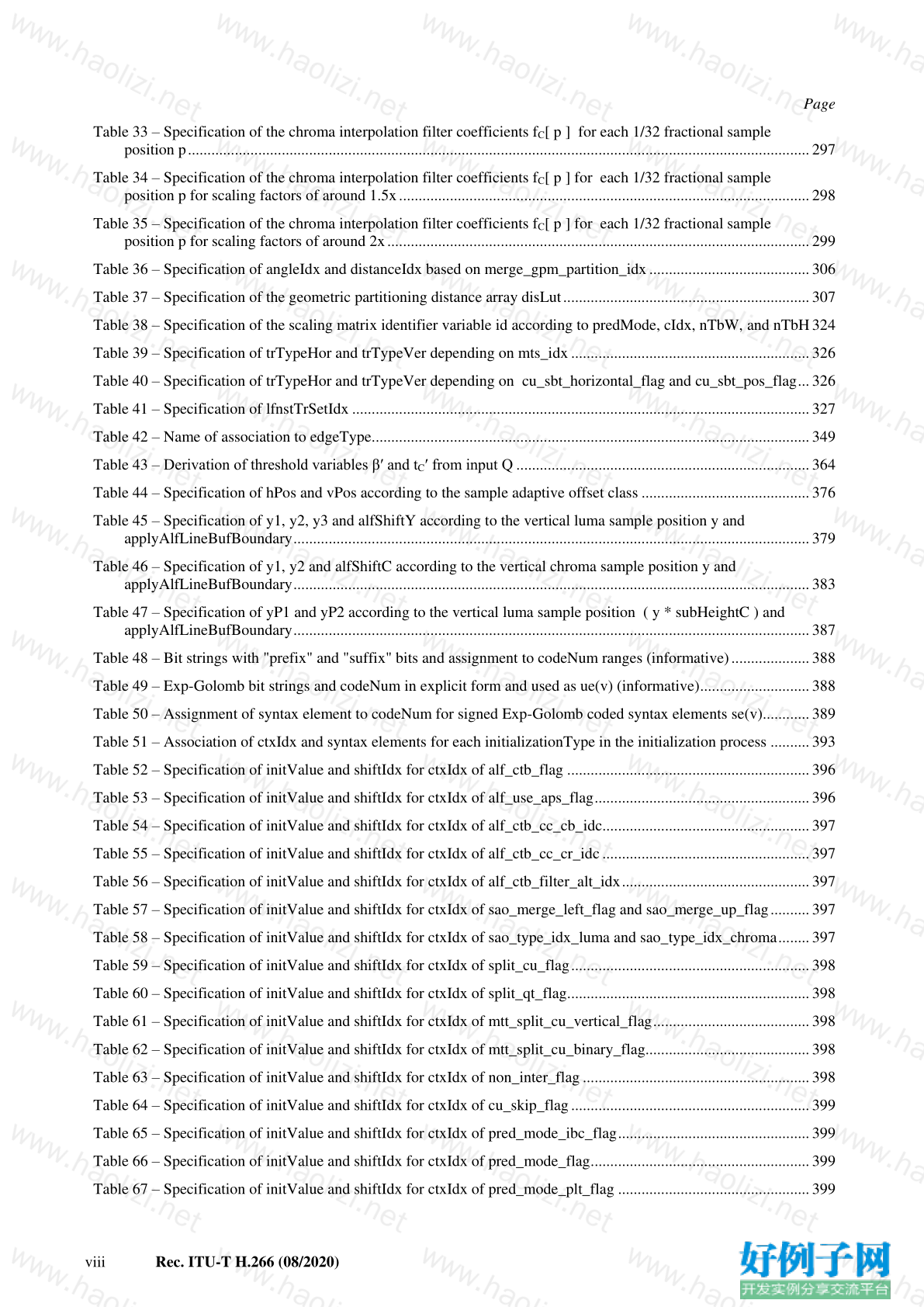
Page
Table 33 – Specification of the chroma interpolation filter coefficients f C [ p ] for each 1/32 fractional sample
position p ............................................................................................................................................................... 297
Table 34 – Specification of the chroma interpolation filter coefficients f C [ p ] for each 1/32 fractional sample
position p for scaling factors of around 1.5x ......................................................................................................... 298
Table 35 – Specification of the chroma interpolation filter coefficients f C [ p ] for each 1/32 fractional sample
position p for scaling factors of around 2x ............................................................................................................ 299
Table 36 – Specification of angleIdx and distanceIdx based on merge_gpm_partition_idx ......................................... 306
Table 37 – Specification of the geometric partitioning distance array disLut ............................................................... 307
Table 38 – Specification of the scaling matrix identifier variable id according to predMode, cIdx, nTbW, and nTbH 324
Table 39 – Specification of trTypeHor and trTypeVer depending on mts_idx ............................................................. 326
Table 40 – Specification of trTypeHor and trTypeVer depending on cu_sbt_horizontal_flag and cu_sbt_pos_flag ... 326
Table 41 – Specification of lfnstTrSetIdx ..................................................................................................................... 327
Table 42 – Name of association to edgeType ................................................................................................................ 349
Table 43 – Derivation of threshold variables β′ and t C ′ from input Q ........................................................................... 364
Table 44 – Specification of hPos and vPos according to the sample adaptive offset class ........................................... 376
Table 45 – Specification of y1, y2, y3 and alfShiftY according to the vertical luma sample position y and
applyAlfLineBufBoundary .................................................................................................................................... 379
Table 46 – Specification of y1, y2 and alfShiftC according to the vertical chroma sample position y and
applyAlfLineBufBoundary .................................................................................................................................... 383
Table 47 – Specification of yP1 and yP2 according to the vertical luma sample position ( y * subHeightC ) and
applyAlfLineBufBoundary .................................................................................................................................... 387
Table 48 – Bit strings with "prefix" and "suffix" bits and assignment to codeNum ranges (informative) .................... 388
Table 49 – Exp-Golomb bit strings and codeNum in explicit form and used as ue(v) (informative) ............................ 388
Table 50 – Assignment of syntax element to codeNum for signed Exp-Golomb coded syntax elements se(v) ............ 389
Table 51 – Association of ctxIdx and syntax elements for each initializationType in the initialization process .......... 393
Table 52 – Specification of initValue and shiftIdx for ctxIdx of alf_ctb_flag .............................................................. 396
Table 53 – Specification of initValue and shiftIdx for ctxIdx of alf_use_aps_flag ....................................................... 396
Table 54 – Specification of initValue and shiftIdx for ctxIdx of alf_ctb_cc_cb_idc ..................................................... 397
Table 55 – Specification of initValue and shiftIdx for ctxIdx of alf_ctb_cc_cr_idc ..................................................... 397
Table 56 – Specification of initValue and shiftIdx for ctxIdx of alf_ctb_filter_alt_idx ................................................ 397
Table 57 – Specification of initValue and shiftIdx for ctxIdx of sao_merge_left_flag and sao_merge_up_flag .......... 397
Table 58 – Specification of initValue and shiftIdx for ctxIdx of sao_type_idx_luma and sao_type_idx_chroma ........ 397
Table 59 – Specification of initValue and shiftIdx for ctxIdx of split_cu_flag ............................................................. 398
Table 60 – Specification of initValue and shiftIdx for ctxIdx of split_qt_flag .............................................................. 398
Table 61 – Specification of initValue and shiftIdx for ctxIdx of mtt_split_cu_vertical_flag ........................................ 398
Table 62 – Specification of initValue and shiftIdx for ctxIdx of mtt_split_cu_binary_flag.......................................... 398
Table 63 – Specification of initValue and shiftIdx for ctxIdx of non_inter_flag .......................................................... 398
Table 64 – Specification of initValue and shiftIdx for ctxIdx of cu_skip_flag ............................................................. 399
Table 65 – Specification of initValue and shiftIdx for ctxIdx of pred_mode_ibc_flag ................................................. 399
Table 66 – Specification of initValue and shiftIdx for ctxIdx of pred_mode_flag ........................................................ 399
Table 67 – Specification of initValue and shiftIdx for ctxIdx of pred_mode_plt_flag ................................................. 399
Rec. ITU-T H.266 (08/2020) ix
Page
Table 68 – Specification of initValue and shiftIdx for ctxIdx of cu_act_enabled_flag ................................................. 399
Table 69 – Specification of initValue and shiftIdx for ctxIdx of intra_bdpcm_luma_flag ........................................... 400
Table 70 – Specification of initValue and shiftIdx for ctxIdx of intra_bdpcm_luma_dir_flag ..................................... 400
Table 71 – Specification of initValue and shiftIdx for ctxIdx of intra_mip_flag .......................................................... 400
Table 72 – Specification of initValue and shiftIdx for ctxIdx of intra_luma_ref_idx ................................................... 400
Table 73 – Specification of initValue and shiftIdx for ctxIdx of intra_subpartitions_mode_flag ................................. 400
Table 74 – Specification of initValue and shiftIdx for ctxIdx of intra_subpartitions_split_flag ................................... 401
Table 75 – Specification of initValue and shiftIdx for ctxIdx of intra_luma_mpm_flag .............................................. 401
Table 76 – Specification of initValue and shiftIdx for ctxIdx of intra_luma_not_planar_flag ..................................... 401
Table 77 – Specification of initValue and shiftIdx for ctxIdx of intra_bdpcm_chroma_flag ........................................ 401
Table 78 – Specification of initValue and shiftIdx for ctxIdx of intra_bdpcm_chroma_dir_flag ................................. 401
Table 79 – Specification of initValue and shiftIdx for ctxIdx of cclm_mode_flag ....................................................... 402
Table 80 – Specification of initValue and shiftIdx for ctxIdx of cclm_mode_idx ........................................................ 402
Table 81 – Specification of initValue and shiftIdx for ctxIdx of intra_chroma_pred_mode ......................................... 402
Table 82 – Specification of initValue and shiftIdx for ctxIdx of general_merge_flag .................................................. 402
Table 83 – Specification of initValue and shiftIdx for ctxIdx of inter_pred_idc .......................................................... 402
Table 84 – Specification of initValue and shiftIdx for ctxIdx of inter_affine_flag ....................................................... 403
Table 85 – Specification of initValue and shiftIdx for ctxIdx of cu_affine_type_flag .................................................. 403
Table 86 – Specification of initValue and shiftIdx for ctxIdx of sym_mvd_flag .......................................................... 403
Table 87 – Specification of initValue and shiftIdx for ctxIdx of ref_idx_l0 and ref_idx_l1 ......................................... 403
Table 88 – Specification of initValue and shiftIdx for ctxIdx of mvp_l0_flag, mvp_l1_flag ....................................... 404
Table 89 – Specification of initValue and shiftIdx for ctxIdx of amvr_flag ................................................................. 404
Table 90 – Specification of initValue and shiftIdx for ctxIdx of amvr_precision_idx .................................................. 404
Table 91 – Specification of initValue and shiftIdx for ctxIdx of bcw_idx .................................................................... 404
Table 92 – Specification of initValue and shiftIdx for ctxIdx of cu_coded_flag .......................................................... 405
Table 93 – Specification of initValue and shiftIdx for ctxIdx of cu_sbt_flag ............................................................... 405
Table 94 – Specification of initValue and shiftIdx for ctxIdx of cu_sbt_quad_flag ..................................................... 405
Table 95 – Specification of initValue and shiftIdx for ctxIdx of cu_sbt_horizontal_flag ............................................. 405
Table 96 – Specification of initValue and shiftIdx for ctxIdx of cu_sbt_pos_flag ........................................................ 406
Table 97 – Specification of initValue and shiftIdx for ctxIdx of lfnst_idx.................................................................... 406
Table 98 – Specification of initValue and shiftIdx for ctxIdx of mts_idx ..................................................................... 406
Table 99 – Specification of initValue and shiftIdx for ctxIdx of copy_above_palette_indices_flag............................. 406
Table 100 – Specification of initValue and shiftIdx for ctxIdx of palette_transpose_flag ............................................ 406
Table 101 – Specification of initValue and shiftIdx for ctxIdx of run_copy_flag ........................................................ 407
Table 102 – Specification of initValue and shiftIdx for ctxIdx of regular_merge_flag ................................................ 407
Table 103 – Specification of initValue and shiftIdx for ctxIdx of mmvd_merge_flag ................................................. 407
Table 104 – Specification of initValue and shiftIdx for ctxIdx of mmvd_cand_flag .................................................... 407
Table 105 – Specification of initValue and shiftIdx for ctxIdx of mmvd_distance_idx ............................................... 408
Table 106 – Specification of initValue and shiftIdx for ctxIdx of ciip_flag.................................................................. 408
x Rec. ITU-T H.266 (08/2020)
Page
Table 107 – Specification of initValue and shiftIdx for ctxIdx of merge_subblock_flag ............................................. 408
Table 108 – Specification of initValue and shiftIdx for ctxIdx of merge_subblock_idx .............................................. 408
Table 109 – Specification of initValue and shiftIdx for ctxIdx of merge_idx, merge_gpm_idx0,
and merge_gpm_idx1. ........................................................................................................................................... 409
Table 110 – Specification of initValue and shiftIdx for ctxIdx of abs_mvd_greater0_flag .......................................... 409
Table 111 – Specification of initValue and shiftIdx for ctxIdx of abs_mvd_greater1_flag .......................................... 409
Table 112 – Specification of initValue and shiftIdx for ctxIdx of tu_y_coded_flag ..................................................... 409
Table 113 – Specification of initValue and shiftIdx for ctxIdx of tu_cb_coded_flag ................................................... 409
Table 114 – Specification of initValue and shiftIdx for ctxIdx of tu_cr_coded_flag .................................................... 410
Table 115 – Specification of initValue and shiftIdx for ctxIdx of cu_qp_delta_abs ..................................................... 410
Table 116 – Specification of initValue and shiftIdx for ctxIdx of cu_chroma_qp_offset_flag ..................................... 410
Table 117 – Specification of initValue and shiftIdx for ctxIdx of cu_chroma_qp_offset_idx ...................................... 410
Table 118 – Specification of initValue and shiftIdx for ctxIdx of transform_skip_flag ............................................... 410
Table 119 – Specification of initValue and shiftIdx for ctxIdx of tu_joint_cbcr_residual_flag .................................... 411
Table 120 – Specification of initValue and shiftIdx for ctxIdx of last_sig_coeff_x_prefix .......................................... 411
Table 121 – Specification of initValue and shiftIdx for ctxIdx of last_sig_coeff_y_prefix .......................................... 411
Table 122 – Specification of initValue and shiftIdx for ctxIdx of sb_coded_flag ........................................................ 412
Table 123 – Specification of initValue and shiftIdx for ctxIdx of sig_coeff_flag ......................................................... 412
Table 124 – Specification of initValue and shiftIdx for ctxIdx of par_level_flag ......................................................... 413
Table 125 – Specification of initValue and shiftIdx for ctxIdx of abs_level_gtx_flag ................................................. 413
Table 126 – Specification of initValue and shiftIdx for ctxIdx of coeff_sign_flag ....................................................... 414
Table 127 – Syntax elements and associated binarizations ........................................................................................... 416
Table 128 – Specification of cRiceParam based on locSumAbs ................................................................................... 421
Table 129 – Bin string of the unary binarization (informative) ..................................................................................... 421
Table 130 – Binarization for intra_chroma_pred_mode................................................................................................ 423
Table 131 – Binarization for inter_pred_idc ................................................................................................................. 423
Table 132 – Assignment of ctxInc to syntax elements with context coded bins ........................................................... 426
Table 133 – Specification of ctxInc using left and above syntax elements ................................................................... 431
Table 134 – Specification of ctxInc depending on binDist and PreviousRunType ....................................................... 436
Table A.1 – General tier and level limits ....................................................................................................................... 446
Table A.2 – Tier and level limits for the video profiles ................................................................................................ 448
Table A.3 – Specification of CpbVclFactor, CpbNalFactor, FormatCapabilityFactor and MinCrScaleFactor............. 448
Table A.4 – Maximum picture rates (pictures per second) at the Main tier, level 1 to 4.1 for some example picture sizes
when MinCbSizeY is equal to 64 .......................................................................................................................... 449
Table A.5 – Maximum picture rates (pictures per second) at the Main tier, level 5 to 6.2 for some example picture sizes
when MinCbSizeY is equal to 64 .......................................................................................................................... 450
Table A.6 – Maximum picture rates (pictures per second) at the High tier, level 1 to 4.1 for some example picture sizes
when MinCbSizeY is equal to 64 .......................................................................................................................... 451
Table A.7 – Maximum picture rates (pictures per second) at the High tier, level 5 to 6.2 for some example picture sizes
when MinCbSizeY is equal to 64 .......................................................................................................................... 452
Table D.1 – Persistence scope of SEI messages (informative) ...................................................................................... 479
Rec. ITU-T H.266 (08/2020) xi
List of Figures
Page
Figure 1 – Nominal vertical and horizontal locations of 4:2:0 luma and chroma samples in a picture ........................... 20
Figure 2 – Nominal vertical and horizontal locations of 4:2:2 luma and chroma samples in a picture ........................... 20
Figure 3 – Nominal vertical and horizontal locations of 4:4:4 luma and chroma samples in a picture ........................... 20
Figure 4 – A picture with 18 by 12 luma CTUs that is partitioned into 12 tiles and 3 raster-scan slices (informative) .. 21
Figure 5 – A picture with 18 by 12 luma CTUs that is partitioned into 24 tiles and 9 rectangular slices (informative) . 22
Figure 6 – A picture that is partitioned into 4 tiles and 4 rectangular slices (informative) ............................................. 22
Figure 7 – A picture that is partitioned into 18 tiles, 24 slices and 24 subpictures (informative) ................................... 23
Figure 8 – Multi-type tree splitting modes indicated by MttSplitMode (informative) .................................................. 163
Figure 9 – Intra prediction directions (informative) ...................................................................................................... 216
Figure 10 – Spatial motion vector neighbours (informative) ........................................................................................ 246
Figure 11 – Flowchart of CABAC parsing process for a syntax element synEl (informative) ..................................... 390
Figure 12 – Spatial neighbour T that is used to invoke the CTB availability derivation process relative to the current
CTB (informative) ................................................................................................................................................. 391
Figure 13 – Flowchart of CABAC initialization process (informative) ........................................................................ 392
Figure 14 – Flowchart of CABAC storage process (informative) ................................................................................. 415
Figure 15 – Flowchart of the arithmetic decoding process for a single bin (informative) ............................................. 437
Figure 16 – Flowchart for decoding a decision ............................................................................................................. 439
Figure 17 – Flowchart of renormalization ..................................................................................................................... 440
Figure 18 – Flowchart of bypass decoding process ....................................................................................................... 440
Figure 19 – Flowchart of decoding a decision before termination ................................................................................ 441
Figure C.1 – Flowchart of classification of byte streams and NAL unit streams for HRD conformance checks .......... 456
Figure C.2 – Flowchart of HRD buffer model .............................................................................................................. 460
好例子网口号:伸出你的我的手 — 分享!
小贴士
感谢您为本站写下的评论,您的评论对其它用户来说具有重要的参考价值,所以请认真填写。
- 类似“顶”、“沙发”之类没有营养的文字,对勤劳贡献的楼主来说是令人沮丧的反馈信息。
- 相信您也不想看到一排文字/表情墙,所以请不要反馈意义不大的重复字符,也请尽量不要纯表情的回复。
- 提问之前请再仔细看一遍楼主的说明,或许是您遗漏了。
- 请勿到处挖坑绊人、招贴广告。既占空间让人厌烦,又没人会搭理,于人于己都无利。
关于好例子网
本站旨在为广大IT学习爱好者提供一个非营利性互相学习交流分享平台。本站所有资源都可以被免费获取学习研究。本站资源来自网友分享,对搜索内容的合法性不具有预见性、识别性、控制性,仅供学习研究,请务必在下载后24小时内给予删除,不得用于其他任何用途,否则后果自负。基于互联网的特殊性,平台无法对用户传输的作品、信息、内容的权属或合法性、安全性、合规性、真实性、科学性、完整权、有效性等进行实质审查;无论平台是否已进行审查,用户均应自行承担因其传输的作品、信息、内容而可能或已经产生的侵权或权属纠纷等法律责任。本站所有资源不代表本站的观点或立场,基于网友分享,根据中国法律《信息网络传播权保护条例》第二十二与二十三条之规定,若资源存在侵权或相关问题请联系本站客服人员,点此联系我们。关于更多版权及免责申明参见 版权及免责申明


网友评论
我要评论