
实例介绍
【实例截图】


【核心代码】
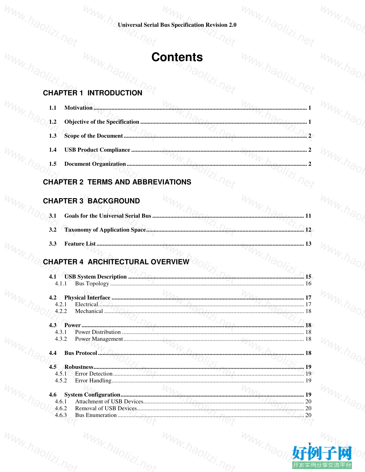
Contents
CHAPTER 1 INTRODUCTION
1.1 Motivation.............................................................................................................................................. 1
1.2 Objective of the Specification............................................................................................................... 1
1.3 Scope of the Document.......................................................................................................................... 2
1.4 USB Product Compliance..................................................................................................................... 2
1.5 Document Organization........................................................................................................................ 2
CHAPTER 2 TERMS AND ABBREVIATIONS
CHAPTER 3 BACKGROUND
3.1 Goals for the Universal Serial Bus..................................................................................................... 11
3.2 Taxonomy of Application Space......................................................................................................... 12
3.3 Feature List.......................................................................................................................................... 13
CHAPTER 4 ARCHITECTURAL OVERVIEW
4.1 USB System Description ..................................................................................................................... 15
4.1.1 Bus Topology................................................................................................................................. 16
4.2 Physical Interface ................................................................................................................................ 17
4.2.1 Electrical......................................................................................................................................... 17
4.2.2 Mechanical..................................................................................................................................... 18
4.3 Power.................................................................................................................................................... 18
4.3.1 Power Distribution ......................................................................................................................... 18
4.3.2 Power Management........................................................................................................................ 18
4.4 Bus Protocol......................................................................................................................................... 18
4.5 Robustness............................................................................................................................................ 19
4.5.1 Error Detection............................................................................................................................... 19
4.5.2 Error Handling................................................................................................................................ 19
4.6 System Configuration.......................................................................................................................... 19
4.6.1 Attachment of USB Devices........................................................................................................... 20
4.6.2 Removal of USB Devices............................................................................................................... 20
4.6.3 Bus Enumeration............................................................................................................................ 20
Universal Serial Bus Specification Revision 2.0
vi
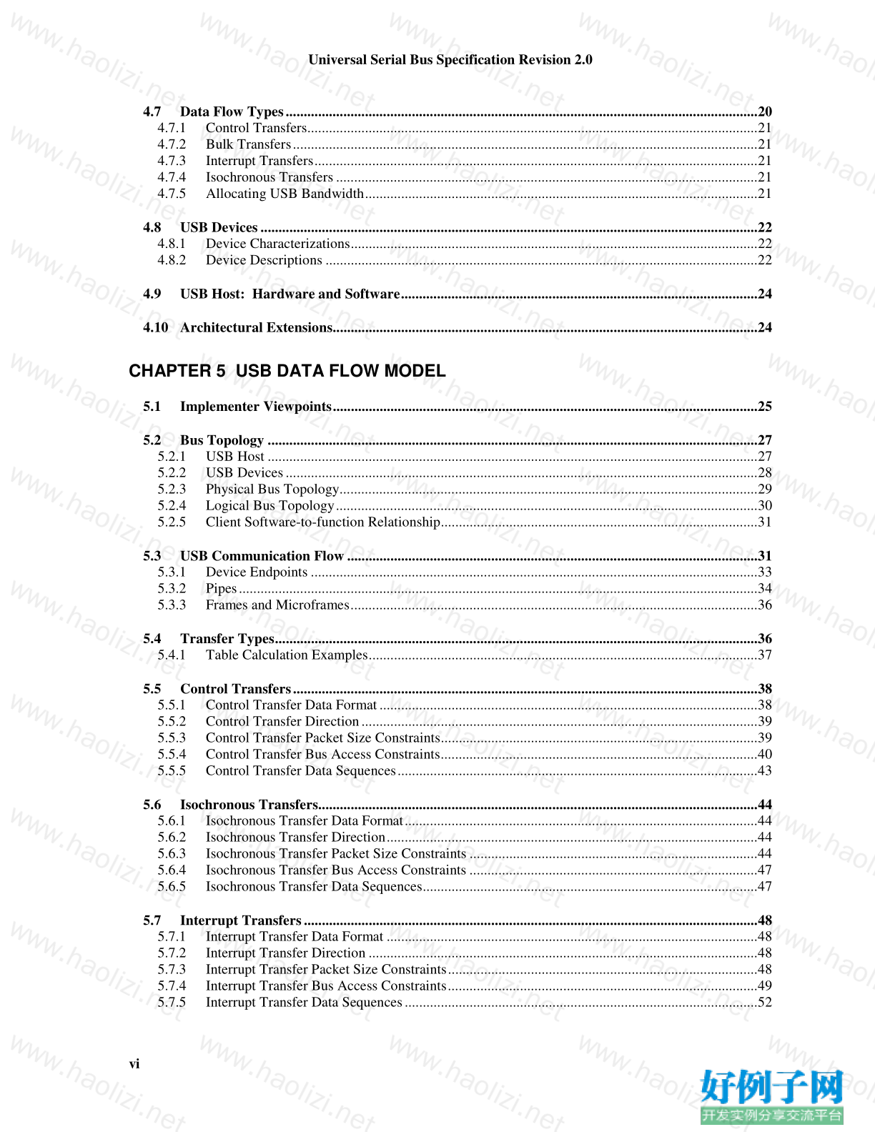
4.7 Data Flow Types...................................................................................................................................20
4.7.1 Control Transfers.............................................................................................................................21
4.7.2 Bulk Transfers.................................................................................................................................21
4.7.3 Interrupt Transfers...........................................................................................................................21
4.7.4 Isochronous Transfers.....................................................................................................................21
4.7.5 Allocating USB Bandwidth.............................................................................................................21
4.8 USB Devices..........................................................................................................................................22
4.8.1 Device Characterizations.................................................................................................................22
4.8.2 Device Descriptions ........................................................................................................................22
4.9 USB Host: Hardware and Software...................................................................................................24
4.10 Architectural Extensions......................................................................................................................24
CHAPTER 5 USB DATA FLOW MODEL
5.1 Implementer Viewpoints......................................................................................................................25
5.2 Bus Topology ........................................................................................................................................27
5.2.1 USB Host ........................................................................................................................................27
5.2.2 USB Devices...................................................................................................................................28
5.2.3 Physical Bus Topology....................................................................................................................29
5.2.4 Logical Bus Topology.....................................................................................................................30
5.2.5 Client Software-to-function Relationship........................................................................................31
5.3 USB Communication Flow ..................................................................................................................31
5.3.1 Device Endpoints ............................................................................................................................33
5.3.2 Pipes................................................................................................................................................34
5.3.3 Frames and Microframes.................................................................................................................36
5.4 Transfer Types......................................................................................................................................36
5.4.1 Table Calculation Examples............................................................................................................37
5.5 Control Transfers.................................................................................................................................38
5.5.1 Control Transfer Data Format.........................................................................................................38
5.5.2 Control Transfer Direction..............................................................................................................39
5.5.3 Control Transfer Packet Size Constraints........................................................................................39
5.5.4 Control Transfer Bus Access Constraints........................................................................................40
5.5.5 Control Transfer Data Sequences....................................................................................................43
5.6 Isochronous Transfers..........................................................................................................................44
5.6.1 Isochronous Transfer Data Format..................................................................................................44
5.6.2 Isochronous Transfer Direction.......................................................................................................44
5.6.3 Isochronous Transfer Packet Size Constraints ................................................................................44
5.6.4 Isochronous Transfer Bus Access Constraints ................................................................................47
5.6.5 Isochronous Transfer Data Sequences.............................................................................................47
5.7 Interrupt Transfers..............................................................................................................................48
5.7.1 Interrupt Transfer Data Format .......................................................................................................48
5.7.2 Interrupt Transfer Direction ............................................................................................................48
5.7.3 Interrupt Transfer Packet Size Constraints......................................................................................48
5.7.4 Interrupt Transfer Bus Access Constraints......................................................................................49
5.7.5 Interrupt Transfer Data Sequences..................................................................................................52
Universal Serial Bus Specification Revision 2.0
vii
5.8 Bulk Transfers..................................................................................................................................... 52
5.8.1 Bulk Transfer Data Format............................................................................................................. 52
5.8.2 Bulk Transfer Direction.................................................................................................................. 52
5.8.3 Bulk Transfer Packet Size Constraints........................................................................................... 53
5.8.4 Bulk Transfer Bus Access Constraints........................................................................................... 53
5.8.5 Bulk Transfer Data Sequences ....................................................................................................... 55
5.9 High-Speed, High Bandwidth Endpoints........................................................................................... 56
5.9.1 High Bandwidth Interrupt Endpoints ............................................................................................. 56
5.9.2 High Bandwidth Isochronous Endpoints........................................................................................ 57
5.10 Split Transactions................................................................................................................................ 58
5.11 Bus Access for Transfers..................................................................................................................... 58
5.11.1 Transfer Management..................................................................................................................... 59
5.11.2 Transaction Tracking...................................................................................................................... 61
5.11.3 Calculating Bus Transaction Times................................................................................................ 63
5.11.4 Calculating Buffer Sizes in Functions and Software...................................................................... 65
5.11.5 Bus Bandwidth Reclamation.......................................................................................................... 65
5.12 Special Considerations for Isochronous Transfers........................................................................... 65
5.12.1 Example Non-USB Isochronous Application................................................................................. 66
5.12.2 USB Clock Model.......................................................................................................................... 69
5.12.3 Clock Synchronization................................................................................................................... 71
5.12.4 Isochronous Devices....................................................................................................................... 71
5.12.5 Data Prebuffering........................................................................................................................... 80
5.12.6 SOF Tracking................................................................................................................................. 81
5.12.7 Error Handling................................................................................................................................ 81
5.12.8 Buffering for Rate Matching.......................................................................................................... 82
CHAPTER 6 MECHANICAL
6.1 Architectural Overview....................................................................................................................... 85
6.2 Keyed Connector Protocol.................................................................................................................. 85
6.3 Cable..................................................................................................................................................... 86
6.4 Cable Assembly.................................................................................................................................... 86
6.4.1 Standard Detachable Cable Assemblies ......................................................................................... 86
6.4.2 High-/full-speed Captive Cable Assemblies................................................................................... 88
6.4.3 Low-speed Captive Cable Assemblies........................................................................................... 90
6.4.4 Prohibited Cable Assemblies.......................................................................................................... 92
6.5 Connector Mechanical Configuration and Material Requirements................................................ 93
6.5.1 USB Icon Location......................................................................................................................... 93
6.5.2 USB Connector Termination Data ................................................................................................. 94
6.5.3 Series “A” and Series “B” Receptacles.......................................................................................... 94
6.5.4 Series “A” and Series “B” Plugs .................................................................................................... 98
Universal Serial Bus Specification Revision 2.0
viii
6.6 Cable Mechanical Configuration and Material Requirements......................................................102
6.6.1 Description....................................................................................................................................102
6.6.2 Construction..................................................................................................................................103
6.6.3 Electrical Characteristics...............................................................................................................105
6.1.4 Cable Environmental Characteristics............................................................................................106
6.1.5 Listing ...........................................................................................................................................106
6.7 Electrical, Mechanical, and Environmental Compliance Standards.............................................106
6.7.1 Applicable Documents..................................................................................................................114
6.8 USB Grounding ..................................................................................................................................114
6.9 PCB Reference Drawings...................................................................................................................114
CHAPTER 7 ELECTRICAL
7.1 Signaling..............................................................................................................................................119
7.1.1 USB Driver Characteristics...........................................................................................................123
7.1.2 Data Signal Rise and Fall, Eye Patterns........................................................................................129
7.1.3 Cable Skew....................................................................................................................................139
7.1.4 Receiver Characteristics................................................................................................................139
7.1.5 Device Speed Identification ..........................................................................................................141
7.1.6 Input Characteristics......................................................................................................................142
7.1.7 Signaling Levels............................................................................................................................144
7.1.8 Data Encoding/Decoding ..............................................................................................................157
7.1.9 Bit Stuffing....................................................................................................................................157
7.1.10 Sync Pattern ..................................................................................................................................159
7.1.11 Data Signaling Rate.......................................................................................................................159
7.1.12 Frame Interval...............................................................................................................................159
7.1.13 Data Source Signaling...................................................................................................................160
7.1.14 Hub Signaling Timings .................................................................................................................162
7.1.15 Receiver Data Jitter.......................................................................................................................164
7.1.16 Cable Delay...................................................................................................................................165
7.1.17 Cable Attenuation..........................................................................................................................167
7.1.18 Bus Turn-around Time and Inter-packet Delay.............................................................................168
7.1.19 Maximum End-to-end Signal Delay..............................................................................................168
7.1.20 Test Mode Support........................................................................................................................169
7.2 Power Distribution.............................................................................................................................171
7.2.1 Classes of Devices.........................................................................................................................171
7.2.2 Voltage Drop Budget ....................................................................................................................175
7.2.3 Power Control During Suspend/Resume.......................................................................................176
7.2.4 Dynamic Attach and Detach..........................................................................................................177
7.3 Physical Layer.....................................................................................................................................178
7.3.1 Regulatory Requirements..............................................................................................................178
7.3.2 Bus Timing/Electrical Characteristics...........................................................................................178
7.3.3 Timing Waveforms .......................................................................................................................191
Universal Serial Bus Specification Revision 2.0
ix
CHAPTER 8 PROTOCOL LAYER
8.1 Byte/Bit Ordering.............................................................................................................................. 195
8.2 SYNC Field......................................................................................................................................... 195
8.3 Packet Field Formats......................................................................................................................... 195
8.3.1 Packet Identifier Field.................................................................................................................. 195
8.3.2 Address Fields.............................................................................................................................. 197
8.3.3 Frame Number Field..................................................................................................................... 197
8.3.4 Data Field..................................................................................................................................... 197
8.3.5 Cyclic Redundancy Checks.......................................................................................................... 198
8.4 Packet Formats.................................................................................................................................. 199
8.4.1 Token Packets............................................................................................................................... 199
8.4.2 Split Transaction Special Token Packets...................................................................................... 199
8.4.3 Start-of-Frame Packets................................................................................................................. 204
8.4.4 Data Packets................................................................................................................................. 206
8.4.5 Handshake Packets....................................................................................................................... 206
8.4.6 Handshake Responses .................................................................................................................. 207
8.5 Transaction Packet Sequences.......................................................................................................... 209
8.5.1 NAK Limiting via Ping Flow Control.......................................................................................... 217
8.5.2 Bulk Transactions......................................................................................................................... 221
8.5.3 Control Transfers.......................................................................................................................... 225
8.5.4 Interrupt Transactions................................................................................................................... 228
8.5.5 Isochronous Transactions............................................................................................................. 229
8.6 Data Toggle Synchronization and Retry ......................................................................................... 232
8.6.1 Initialization via SETUP Token ................................................................................................... 233
8.6.2 Successful Data Transactions....................................................................................................... 233
8.6.3 Data Corrupted or Not Accepted.................................................................................................. 233
8.6.4 Corrupted ACK Handshake.......................................................................................................... 234
8.6.5 Low-speed Transactions............................................................................................................... 235
8.7 Error Detection and Recovery.......................................................................................................... 236
8.7.1 Packet Error Categories................................................................................................................ 236
8.7.2 Bus Turn-around Timing.............................................................................................................. 237
8.7.3 False EOPs ................................................................................................................................... 237
8.7.4 Babble and Loss of Activity Recovery......................................................................................... 238
Universal Serial Bus Specification Revision 2.0
x
CHAPTER 9 USB DEVICE FRAMEWORK
9.1 USB Device States...............................................................................................................................239
9.1.1 Visible Device States.....................................................................................................................239
9.1.2 Bus Enumeration...........................................................................................................................243
9.2 Generic USB Device Operations .......................................................................................................244
9.2.1 Dynamic Attachment and Removal...............................................................................................244
9.2.2 Address Assignment......................................................................................................................244
9.2.3 Configuration ................................................................................................................................244
9.2.4 Data Transfer.................................................................................................................................245
9.2.5 Power Management.......................................................................................................................245
9.2.6 Request Processing........................................................................................................................245
9.2.7 Request Error ................................................................................................................................247
9.3 USB Device Requests..........................................................................................................................248
9.3.1 bmRequestType.............................................................................................................................248
9.3.2 bRequest........................................................................................................................................249
9.3.3 wValue ..........................................................................................................................................249
9.3.4 wIndex...........................................................................................................................................249
9.3.5 wLength.........................................................................................................................................249
9.4 Standard Device Requests .................................................................................................................250
9.4.1 Clear Feature.................................................................................................................................252
9.4.2 Get Configuration..........................................................................................................................253
9.4.3 Get Descriptor...............................................................................................................................253
9.4.4 Get Interface..................................................................................................................................254
9.4.5 Get Status......................................................................................................................................254
9.4.6 Set Address....................................................................................................................................256
9.4.7 Set Configuration..........................................................................................................................257
9.4.8 Set Descriptor................................................................................................................................257
9.4.9 Set Feature.....................................................................................................................................258
9.4.10 Set Interface...................................................................................................................................259
9.4.11 Synch Frame..................................................................................................................................260
9.5 Descriptors..........................................................................................................................................260
9.6 Standard USB Descriptor Definitions...............................................................................................261
9.6.1 Device ...........................................................................................................................................261
9.6.2 Device_Qualifier...........................................................................................................................264
9.6.3 Configuration ................................................................................................................................264
9.6.4 Other_Speed_Configuration..........................................................................................................266
9.6.5 Interface.........................................................................................................................................267
9.6.6 Endpoint........................................................................................................................................269
9.6.7 String.............................................................................................................................................273
9.7 Device Class Definitions.....................................................................................................................274
9.7.1 Descriptors ....................................................................................................................................274
9.7.2 Interface(s) and Endpoint Usage...................................................................................................274
9.7.3 Requests ........................................................................................................................................274
Universal Serial Bus Specification Revision 2.0
xi
CHAPTER 10 USB HOST: HARDWARE AND SOFTWARE
10.1 Overview of the USB Host ................................................................................................................ 275
10.1.1 Overview...................................................................................................................................... 275
10.1.2 Control Mechanisms..................................................................................................................... 278
10.1.3 Data Flow..................................................................................................................................... 278
10.1.4 Collecting Status and Activity Statistics....................................................................................... 279
10.1.5 Electrical Interface Considerations............................................................................................... 279
10.2 Host Controller Requirements ......................................................................................................... 279
10.2.1 State Handling.............................................................................................................................. 280
10.2.2 Serializer/Deserializer .................................................................................................................. 280
10.2.3 Frame and Microframe Generation .............................................................................................. 280
10.2.4 Data Processing............................................................................................................................ 281
10.2.5 Protocol Engine............................................................................................................................ 281
10.2.6 Transmission Error Handling....................................................................................................... 282
10.2.7 Remote Wakeup........................................................................................................................... 282
10.2.8 Root Hub...................................................................................................................................... 282
10.2.9 Host System Interface................................................................................................................... 283
10.3 Overview of Software Mechanisms.................................................................................................. 283
10.3.1 Device Configuration................................................................................................................... 283
10.3.2 Resource Management ................................................................................................................. 285
10.3.3 Data Transfers .............................................................................................................................. 286
10.3.4 Common Data Definitions............................................................................................................ 286
10.4 Host Controller Driver...................................................................................................................... 287
10.5 Universal Serial Bus Driver.............................................................................................................. 287
10.5.1 USBD Overview........................................................................................................................... 288
10.5.2 USBD Command Mechanism Requirements............................................................................... 289
10.5.3 USBD Pipe Mechanisms.............................................................................................................. 291
10.5.4 Managing the USB via the USBD Mechanisms........................................................................... 293
10.5.5 Passing USB Preboot Control to the Operating System............................................................... 295
10.6 Operating System Environment Guides.......................................................................................... 296
CHAPTER 11 HUB SPECIFICATION
11.1 Overview............................................................................................................................................. 297
11.1.1 Hub Architecture.......................................................................................................................... 297
11.1.2 Hub Connectivity.......................................................................................................................... 298
11.2 Hub Frame/Microframe Timer........................................................................................................ 300
11.2.1 High-speed Microframe Timer Range.......................................................................................... 300
11.2.2 Full-speed Frame Timer Range.................................................................................................... 301
11.2.3 Frame/Microframe Timer Synchronization.................................................................................. 301
11.2.4 Microframe Jitter Related to Frame Jitter..................................................................................... 303
11.2.5 EOF1 and EOF2 Timing Points.................................................................................................... 303
Universal Serial Bus Specification Revision 2.0
xii
11.3 Host Behavior at End-of-Frame........................................................................................................306
11.3.1 Full-/low-speed Latest Host Packet...............................................................................................306
11.3.2 Full-/low-speed Packet Nullification.............................................................................................306
11.3.3 Full-/low-speed Transaction Completion Prediction.....................................................................306
11.4 Internal Port .......................................................................................................................................307
11.4.1 Inactive..........................................................................................................................................308
11.4.2 Suspend Delay...............................................................................................................................308
11.4.3 Full Suspend (Fsus).......................................................................................................................308
11.4.4 Generate Resume (GResume).......................................................................................................308
11.5 Downstream Facing Ports..................................................................................................................309
11.5.1 Downstream Facing Port State Descriptions.................................................................................312
11.5.2 Disconnect Detect Timer...............................................................................................................315
11.5.3 Port Indicator.................................................................................................................................316
11.6 Upstream Facing Port........................................................................................................................318
11.6.1 Full-speed......................................................................................................................................318
11.6.2 High-speed ....................................................................................................................................318
11.6.3 Receiver.........................................................................................................................................318
11.6.4 Transmitter....................................................................................................................................322
11.7 Hub Repeater......................................................................................................................................324
11.7.1 High-speed Packet Connectivity...................................................................................................324
11.7.2 Hub Repeater State Machine.........................................................................................................327
11.7.3 Wait for Start of Packet from Upstream Port (WFSOPFU)..........................................................329
11.7.4 Wait for End of Packet from Upstream Port (WFEOPFU)...........................................................330
11.7.5 Wait for Start of Packet (WFSOP)................................................................................................330
11.7.6 Wait for End of Packet (WFEOP).................................................................................................330
11.8 Bus State Evaluation..........................................................................................................................330
11.8.1 Port Error.......................................................................................................................................330
11.8.2 Speed Detection.............................................................................................................................331
11.8.3 Collision........................................................................................................................................331
11.8.4 Low-speed Port Behavior..............................................................................................................331
11.9 Suspend and Resume..........................................................................................................................332
11.10 Hub Reset Behavior............................................................................................................................334
11.11 Hub Port Power Control....................................................................................................................335
11.11.1 Multiple Gangs..............................................................................................................................335
11.12 Hub Controller ...................................................................................................................................336
11.12.1 Endpoint Organization ..................................................................................................................336
11.12.2 Hub Information Architecture and Operation ...............................................................................337
11.12.3 Port Change Information Processing.............................................................................................337
11.12.4 Hub and Port Status Change Bitmap.............................................................................................338
11.12.5 Over-current Reporting and Recovery ..........................................................................................339
11.12.6 Enumeration Handling ..................................................................................................................340
11.13 Hub Configuration.............................................................................................................................340
Universal Serial Bus Specification Revision 2.0
xiii
11.14 Transaction Translator..................................................................................................................... 342
11.14.1 Overview...................................................................................................................................... 342
11.14.2 Transaction Translator Scheduling............................................................................................... 344
11.15 Split Transaction Notation Information.......................................................................................... 346
11.16 Common Split Transaction State Machines.................................................................................... 349
11.16.1 Host Controller State Machine..................................................................................................... 350
11.16.2 Transaction Translator State Machine.......................................................................................... 354
11.17 Bulk/Control Transaction Translation Overview........................................................................... 360
11.17.1 Bulk/Control Split Transaction Sequences................................................................................... 360
11.17.2 Bulk/Control Split Transaction State Machines........................................................................... 366
11.17.3 Bulk/Control Sequencing............................................................................................................. 371
11.17.4 Bulk/Control Buffering Requirements ......................................................................................... 372
11.17.5 Other Bulk/Control Details........................................................................................................... 372
11.18 Periodic Split Transaction Pipelining and Buffer Management.................................................... 372
11.18.1 Best Case Full-Speed Budget....................................................................................................... 373
11.18.2 TT Microframe Pipeline............................................................................................................... 373
11.18.3 Generation of Full-speed Frames ................................................................................................. 374
11.18.4 Host Split Transaction Scheduling Requirements........................................................................ 374
11.18.5 TT Response Generation.............................................................................................................. 378
11.18.6 TT Periodic Transaction Handling Requirements........................................................................ 379
11.18.7 TT Transaction Tracking.............................................................................................................. 380
11.18.8 TT Complete-split Transaction State Searching........................................................................... 381
11.19 Approximate TT Buffer Space Required ........................................................................................ 382
11.20 Interrupt Transaction Translation Overview................................................................................. 382
11.20.1 Interrupt Split Transaction Sequences.......................................................................................... 383
11.20.2 Interrupt Split Transaction State Machines .................................................................................. 386
11.20.3 Interrupt OUT Sequencing........................................................................................................... 392
11.20.4 Interrupt IN Sequencing............................................................................................................... 393
11.21 Isochronous Transaction Translation Overview ............................................................................ 394
11.21.1 Isochronous Split Transaction Sequences .................................................................................... 395
11.21.2 Isochronous Split Transaction State Machines............................................................................. 398
11.21.3 Isochronous OUT Sequencing...................................................................................................... 403
11.21.4 Isochronous IN Sequencing.......................................................................................................... 404
11.22 TT Error Handling............................................................................................................................ 404
11.22.1 Loss of TT Synchronization With HS SOFs ................................................................................ 404
11.22.2 TT Frame and Microframe Timer Synchronization Requirements .............................................. 405
11.23 Descriptors ......................................................................................................................................... 407
11.23.1 Standard Descriptors for Hub Class ............................................................................................. 407
11.23.2 Class-specific Descriptors............................................................................................................ 417
11.24 Requests.............................................................................................................................................. 419
11.24.1 Standard Requests ........................................................................................................................ 419
11.24.2 Class-specific Requests................................................................................................................ 420
Universal Serial Bus Specification Revision 2.0
xiv
APPENDIX A TRANSACTION EXAMPLES
A.1 Bulk/Control OUT and SETUP Transaction Examples..................................................................439
A.2 Bulk/Control IN Transaction Examples...........................................................................................464
A.3 Interrupt OUT Transaction Examples.............................................................................................489
A.4 Interrupt IN Transaction Examples.................................................................................................509
A.5 Isochronous OUT SpAppendix A Transaction Examples
APPENDIX B EXAMPLE DECLARATIONS FOR STATE MACHINES
B.1 Global Declarations............................................................................................................................555
B.2 Host Controller Declarations.............................................................................................................558
B.3 Transaction Translator Declarations................................................................................................560
APPENDIX C RESET PROTOCOL STATE DIAGRAMS
C.1 Downstream Facing Port State Diagram..........................................................................................565
C.2 Upstream Facing Port State Diagram...............................................................................................567
C.2.1 Reset From Suspended State.........................................................................................................567
C.2.2 Reset From Full-speed Non-suspended State................................................................................570
C.2.3 Reset From High-speed Non-suspended State ..............................................................................570
C.2.4 Reset Handshake...........................................................................................................................570
INDEX
Universal Serial Bus Specification Revision 2.0
xv
Figures
Figure 3-1. Application Space Taxonomy...........................................................................................................12
Figure 4-1. Bus Topology....................................................................................................................................16
Figure 4-2. USB Cable.........................................................................................................................................17
Figure 4-3. A Typical Hub...................................................................................................................................23
Figure 4-4. Hubs in a Desktop Computer Environment.......................................................................................23
Figure 5-1. Simple USB Host/Device View........................................................................................................25
Figure 5-2. USB Implementation Areas...............................................................................................................26
Figure 5-3. Host Composition..............................................................................................................................27
Figure 5-4. Physical Device Composition ...........................................................................................................28
Figure 5-5. USB Physical Bus Topology.............................................................................................................29
Figure 5-6. Multiple Full-speed Buses in a High-speed System..........................................................................30
Figure 5-7. USB Logical Bus Topology..............................................................................................................30
Figure 5-8. Client Software-to-function Relationships........................................................................................31
Figure 5-9. USB Host/Device Detailed View......................................................................................................32
Figure 5-10. USB Communication Flow.............................................................................................................33
Figure 5-11. Data Phase PID Sequence for Isochronous IN High Bandwidth Endpoints....................................57
Figure 5-12. Data Phase PID Sequence for Isochronous OUT High Bandwidth Endpoints................................58
Figure 5-13. USB Information Conversion From Client Software to Bus...........................................................59
Figure 5-14. Transfers for Communication Flows...............................................................................................62
Figure 5-15. Arrangement of IRPs to Transactions/(Micro)frames.....................................................................63
Figure 5-16. Non-USB Isochronous Example.....................................................................................................67
Figure 5-17. USB Full-speed Isochronous Application.......................................................................................70
Figure 5-18. Example Source/Sink Connectivity.................................................................................................77
Figure 5-19. Data Prebuffering............................................................................................................................81
Figure 5-20. Packet and Buffer Size Formulas for Rate-matched Isochronous Transfers...................................83
Figure 6-1. Keyed Connector Protocol................................................................................................................85
Figure 6-2. USB Standard Detachable Cable Assembly......................................................................................87
Figure 6-3. USB High-/full-speed Hardwired Cable Assembly...........................................................................89
Figure 6-4. USB Low-speed Hardwired Cable Assembly...................................................................................91
Figure 6-5. USB Icon...........................................................................................................................................93
Figure 6-6. Typical USB Plug Orientation ..........................................................................................................93
Figure 6-7. USB Series "A" Receptacle Interface and Mating Drawing..............................................................95
Figure 6-8. USB Series "B" Receptacle Interface and Mating Drawing..............................................................96
Universal Serial Bus Specification Revision 2.0
xvi
Figure 6-9. USB Series "A" Plug Interface Drawing...........................................................................................99
Figure 6-10. USB Series “B” Plug Interface Drawing.......................................................................................100
Figure 6-11. Typical High-/full-speed Cable Construction ...............................................................................102
Figure 6-12. Single Pin-type Series "A" Receptacle..........................................................................................115
Figure 6-13. Dual Pin-type Series "A" Receptacle............................................................................................116
Figure 6-14. Single Pin-type Series "B" Receptacle..........................................................................................117
Figure 7-1. Example High-speed Capable Transceiver Circuit .........................................................................120
Figure 7-2. Maximum Input Waveforms for USB Signaling.............................................................................124
Figure 7-3. Example Full-speed CMOS Driver Circuit (non High-speed capable)...........................................125
Figure 7-4. Full-speed Buffer V/I Characteristics..............................................................................................126
Figure 7-5. Full-speed Buffer V/I Characteristics for High-speed Capable Transceiver...................................127
Figure 7-6. Full-speed Signal Waveforms.........................................................................................................128
Figure 7-7. Low-speed Driver Signal Waveforms.............................................................................................128
Figure 7-8. Data Signal Rise and Fall Time.......................................................................................................130
Figure 7-9. Full-speed Load...............................................................................................................................130
Figure 7-10. Low-speed Port Loads...................................................................................................................131
Figure 7-11. Measurement Planes.....................................................................................................................131
Figure 7-12. Transmitter/Receiver Test Fixture ................................................................................................132
Figure 7-13. Template 1.....................................................................................................................................133
Figure 7-14. Template 2.....................................................................................................................................134
Figure 7-15. Template 3.....................................................................................................................................135
Figure 7-16. Template 4.....................................................................................................................................136
Figure 7-17. Template 5.....................................................................................................................................137
Figure 7-18. Template 6.....................................................................................................................................138
Figure 7-19. Differential Input Sensitivity Range for Low-/full-speed.............................................................140
Figure 7-20. Full-speed Device Cable and Resistor Connections......................................................................141
Figure 7-21. Low-speed Device Cable and Resistor Connections.....................................................................141
Figure 7-22. Placement of Optional Edge Rate Control Capacitors for Low-/full-speed..................................143
Figure 7-23. Diagram for High-speed Loading Equivalent Circuit...................................................................143
Figure 7-24. Upstream Facing Full-speed Port Transceiver..............................................................................146
Figure 7-25. Downstream Facing Low-/full-speed Port Transceiver.................................................................146
Figure 7-26. Low-/full-speed Disconnect Detection..........................................................................................149
Figure 7-27. Full-/high-speed Device Connect Detection .................................................................................149
Figure 7-28. Low-speed Device Connect Detection..........................................................................................150
Figure 7-29. Power-on and Connection Events Timing.....................................................................................150
Figure 7-30. Low-/full-speed Packet Voltage Levels........................................................................................152
Figure 7-31. NRZI Data Encoding.....................................................................................................................157
Universal Serial Bus Specification Revision 2.0
xvii
Figure 7-32. Bit Stuffing....................................................................................................................................157
Figure 7-33. Illustration of Extra Bit Preceding EOP (Full-/low-speed) ...........................................................158
Figure 7-34. Flow Diagram for Bit Stuffing......................................................................................................158
Figure 7-35. Sync Pattern (Low-/full-speed).....................................................................................................159
Figure 7-36. Data Jitter Taxonomy....................................................................................................................160
Figure 7-37. SE0 for EOP Width Timing..........................................................................................................161
Figure 7-38. Hub Propagation Delay of Full-speed Differential Signals...........................................................162
Figure 7-39. Full-speed Cable Delay.................................................................................................................166
Figure 7-40. Low-speed Cable Delay................................................................................................................166
Figure 7-41. Worst-case End-to-end Signal Delay Model for Low-/full-speed.................................................169
Figure 7-42. Compound Bus-powered Hub.......................................................................................................172
Figure 7-43. Compound Self-powered Hub.......................................................................................................173
Figure 7-44. Low-power Bus-powered Function...............................................................................................174
Figure 7-45. High-power Bus-powered Function..............................................................................................174
Figure 7-46. Self-powered Function..................................................................................................................175
Figure 7-47. Worst-case Voltage Drop Topology (Steady State)......................................................................175
Figure 7-48. Typical Suspend Current Averaging Profile .................................................................................176
Figure 7-49. Differential Data Jitter for Low-/full-speed...................................................................................191
Figure 7-50. Differential-to-EOP Transition Skew and EOP Width for Low-/full-speed .................................191
Figure 7-51. Receiver Jitter Tolerance for Low-/full-speed...............................................................................191
Figure 7-52. Hub Differential Delay, Differential Jitter, and SOP Distortion for Low-/full-speed...................192
Figure 7-53. Hub EOP Delay and EOP Skew for Low-/full-speed....................................................................193
Figure 8-1. PID Format......................................................................................................................................195
Figure 8-2. ADDR Field....................................................................................................................................197
Figure 8-3. Endpoint Field.................................................................................................................................197
Figure 8-4. Data Field Format ...........................................................................................................................198
Figure 8-5. Token Format..................................................................................................................................199
Figure 8-6. Packets in a Start-split Transaction.................................................................................................200
Figure 8-7. Packets in a Complete-split Transaction.........................................................................................200
Figure 8-8. Relationship of Interrupt IN Transaction to High-speed Split Transaction.....................................201
Figure 8-9. Relationship of Interrupt OUT Transaction to High-speed Split OUT Transaction........................202
Figure 8-10. Start-split (SSPLIT) Token ...........................................................................................................202
Figure 8-11. Port Field.......................................................................................................................................203
Figure 8-12. Complete-split (CSPLIT) Transaction Token...............................................................................204
Figure 8-13. SOF Packet....................................................................................................................................204
Figure 8-14. Relationship between Frames and Microframes ...........................................................................205
Figure 8-15. Data Packet Format.......................................................................................................................206
Universal Serial Bus Specification Revision 2.0
xviii
Figure 8-16. Handshake Packet.........................................................................................................................206
Figure 8-17. Legend for State Machines............................................................................................................210
Figure 8-18. State Machine Context Overview .................................................................................................211
Figure 8-19. Host Controller Top Level Transaction State Machine Hierarchy Overview...............................211
Figure 8-20. Host Controller Non-split Transaction State Machine Hierarchy Overview.................................212
Figure 8-21. Device Transaction State Machine Hierarchy Overview..............................................................212
Figure 8-22. Device Top Level State Machine..................................................................................................213
Figure 8-23. Device_process_Trans State Machine...........................................................................................213
Figure 8-24. Dev_do_OUT State Machine........................................................................................................214
Figure 8-25. Dev_do_IN State Machine............................................................................................................215
Figure 8-26. HC_Do_nonsplit State Machine....................................................................................................216
Figure 8-27. Host High-speed Bulk OUT/Control Ping State Machine.............................................................218
Figure 8-28. Dev_HS_ping State Machine........................................................................................................219
Figure 8-29. Device High-speed Bulk OUT /Control State Machine................................................................220
Figure 8-30. Bulk Transaction Format...............................................................................................................221
Figure 8-31. Bulk/Control/Interrupt OUT Transaction Host State Machine .....................................................222
Figure 8-32. Bulk/Control/Interrupt OUT Transaction Device State Machine..................................................223
Figure 8-33. Bulk/Control/Interrupt IN Transaction Host State Machine .........................................................224
Figure 8-34. Bulk/Control/Interrupt IN Transaction Device State Machine......................................................225
Figure 8-35. Bulk Reads and Writes..................................................................................................................225
Figure 8-36. Control SETUP Transaction..........................................................................................................226
Figure 8-37. Control Read and Write Sequences...............................................................................................226
Figure 8-38. Interrupt Transaction Format ........................................................................................................229
Figure 8-39. Isochronous Transaction Format...................................................................................................229
Figure 8-40. Isochronous OUT Transaction Host State Machine......................................................................230
Figure 8-41. Isochronous OUT Transaction Device State Machine..................................................................231
Figure 8-42. Isochronous IN Transaction Host State Machine..........................................................................231
Figure 8-43. Isochronous IN Transaction Device State Machine......................................................................232
Figure 8-44. SETUP Initialization.....................................................................................................................233
Figure 8-45. Consecutive Transactions..............................................................................................................233
Figure 8-46. NAKed Transaction with Retry.....................................................................................................234
Figure 8-47. Corrupted ACK Handshake with Retry.........................................................................................234
Figure 8-48. Low-speed Transaction.................................................................................................................235
Figure 8-49. Bus Turn-around Timer Usage......................................................................................................237
Figure 9-1. Device State Diagram .....................................................................................................................240
Figure 9-2. wIndex Format when Specifying an Endpoint................................................................................249
Figure 9-3. wIndex Format when Specifying an Interface ................................................................................249
Universal Serial Bus Specification Revision 2.0
xix
Figure 9-4. Information Returned by a GetStatus() Request to a Device ..........................................................255
Figure 9-5. Information Returned by a GetStatus() Request to an Interface......................................................255
Figure 9-6. Information Returned by a GetStatus() Request to an Endpoint.....................................................256
Figure 9-7. Example of Feedback Endpoint Numbers.......................................................................................272
Figure 9-8. Example of Feedback Endpoint Relationships................................................................................272
Figure 10-1. Interlayer Communications Model................................................................................................275
Figure 10-2. Host Communications...................................................................................................................276
Figure 10-3. Frame and Microframe Creation...................................................................................................281
Figure 10-4. Configuration Interactions.............................................................................................................284
Figure 10-5. Universal Serial Bus Driver Structure...........................................................................................288
Figure 11-1. Hub Architecture...........................................................................................................................298
Figure 11-2. Hub Signaling Connectivity..........................................................................................................299
Figure 11-3. Resume Connectivity....................................................................................................................299
Figure 11-4. Example High-speed EOF Offsets Due to Propagation Delay Without EOF Advancement ........302
Figure 11-5. Example High-speed EOF Offsets Due to Propagation Delay With EOF Advancement..............302
Figure 11-6. High-speed EOF2 Timing Point....................................................................................................304
Figure 11-7. High-speed EOF1 Timing Point....................................................................................................304
Figure 11-8. Full-speed EOF Timing Points......................................................................................................304
Figure 11-9. Internal Port State Machine...........................................................................................................308
Figure 11-10. Downstream Facing Hub Port State Machine .............................................................................310
Figure 11-11. Port Indicator State Diagram.......................................................................................................317
Figure 11-12. Upstream Facing Port Receiver State Machine...........................................................................319
Figure 11-13. Upstream Facing Port Transmitter State Machine ......................................................................322
Figure 11-14. Example Hub Repeater Organization..........................................................................................324
Figure 11-15. High-speed Port Selector State Machine.....................................................................................326
Figure 11-16. Hub Repeater State Machine.......................................................................................................328
Figure 11-17. Example Remote-wakeup Resume Signaling With Full-/low-speed Device..............................333
Figure 11-18. Example Remote-wakeup Resume Signaling With High-speed Device.....................................334
Figure 11-19. Example Hub Controller Organization........................................................................................336
Figure 11-20. Relationship of Status, Status Change, and Control Information to Device States.....................337
Figure 11-21. Port Status Handling Method......................................................................................................338
Figure 11-22. Hub and Port Status Change Bitmap...........................................................................................339
Figure 11-23. Example Hub and Port Change Bit Sampling.............................................................................339
Figure 11-24. Transaction Translator Overview................................................................................................342
Figure 11-25. Periodic and Non-periodic Buffer Sections of TT.......................................................................343
Figure 11-26. TT Microframe Pipeline for Periodic Split Transactions............................................................344
Figure 11-27. TT Nonperiodic Buffering...........................................................................................................345
Universal Serial Bus Specification Revision 2.0
xx
Figure 11-28. Example Full-/low-speed Handler Scheduling for Start-splits....................................................346
Figure 11-29. Flow Sequence Legend...............................................................................................................346
Figure 11-30. Legend for State Machines..........................................................................................................347
Figure 11-31. State Machine Context Overview ...............................................................................................348
Figure 11-32. Host Controller Split Transaction State Machine Hierarchy Overview......................................349
Figure 11-33. Transaction Translator State Machine Hierarchy Overview.......................................................350
Figure 11-34. Host Controller............................................................................................................................350
Figure 11-35. HC_Process_Command..............................................................................................................351
Figure 11-36. HC_Do_Start...............................................................................................................................352
Figure 11-37. HC_Do_Complete.......................................................................................................................353
Figure 11-38. Transaction Translator ................................................................................................................354
Figure 11-39. TT_Process_Packet.....................................................................................................................355
Figure 11-40. TT_Do_Start ...............................................................................................................................356
Figure 11-41. TT_Do_Complete .......................................................................................................................357
Figure 11-42. TT_BulkSS..................................................................................................................................357
Figure 11-43. TT_BulkCS.................................................................................................................................358
Figure 11-44. TT_IntSS.....................................................................................................................................358
Figure 11-45. TT_IntCS ....................................................................................................................................359
Figure 11-46. TT_IsochSS.................................................................................................................................359
Figure 11-47. Sample Algorithm for Compare_buffs........................................................................................361
Figure 11-48. Bulk/Control OUT Start-split Transaction Sequence..................................................................362
Figure 11-49. Bulk/Control OUT Complete-split Transaction Sequence..........................................................363
Figure 11-50. Bulk/Control IN Start-split Transaction Sequence......................................................................364
Figure 11-51. Bulk/Control IN Complete-split Transaction Sequence..............................................................365
Figure 11-52. Bulk/Control OUT Start-split Transaction Host State Machine..................................................366
Figure 11-53. Bulk/Control OUT Complete-split Transaction Host State Machine..........................................367
Figure 11-54. Bulk/Control OUT Start-split Transaction TT State Machine ....................................................368
Figure 11-55. Bulk/Control OUT Complete-split Transaction TT State Machine ............................................368
Figure 11-56. Bulk/Control IN Start-split Transaction Host State Machine......................................................369
Figure 11-57. Bulk/Control IN Complete-split Transaction Host State Machine..............................................370
Figure 11-58. Bulk/Control IN Start-split Transaction TT State Machine ........................................................371
Figure 11-59. Bulk/Control IN Complete-split Transaction TT State Machine ................................................371
Figure 11-60. Best Case Budgeted Full-speed Wire Time With No Bit Stuffing..............................................373
Figure 11-61. Scheduling of TT Microframe Pipeline.......................................................................................374
Figure 11-62. Isochronous OUT Example That Avoids a Start-split-end With Zero Data................................375
Figure 11-63. End of Frame TT Pipeline Scheduling Example.........................................................................376
Figure 11-64. Isochronous IN Complete-split Schedule Example at L=Y 6 .......................................................377
Universal Serial Bus Specification Revision 2.0
xxi
Figure 11-65. Isochronous IN Complete-split Schedule Example at L=Y 7 .......................................................377
Figure 11-66. Microframe Pipeline....................................................................................................................380
Figure 11-67. Advance_Pipeline Pseudocode....................................................................................................381
Figure 11-68. Interrupt OUT Start-split Transaction Sequence.........................................................................383
Figure 11-69. Interrupt OUT Complete-split Transaction Sequence.................................................................384
Figure 11-70. Interrupt IN Start-split Transaction Sequence.............................................................................385
Figure 11-71. Interrupt IN Complete-split Transaction Sequence.....................................................................385
Figure 11-72. Interrupt OUT Start-split Transaction Host State Machine.........................................................386
Figure 11-73. Interrupt OUT Complete-split Transaction Host State Machine.................................................387
Figure 11-74. Interrupt OUT Start-split Transaction TT State Machine............................................................388
Figure 11-75. Interrupt OUT Complete-split Transaction TT State Machine....................................................389
Figure 11-76. Interrupt IN Start-split Transaction Host State Machine.............................................................389
Figure 11-77. Interrupt IN Complete-split Transaction Host State Machine.....................................................390
Figure 11-78. HC_Data_or_Error State Machine..............................................................................................391
Figure 11-79. Interrupt IN Start-split Transaction TT State Machine................................................................391
Figure 11-80. Interrupt IN Complete-split Transaction TT State Machine........................................................392
Figure 11-81. Example of CRC16 Handling for Interrupt OUT........................................................................393
Figure 11-82. Example of CRC16 Handling for Interrupt IN............................................................................394
Figure 11-83. Isochronous OUT Start-split Transaction Sequence....................................................................395
Figure 11-84. Isochronous IN Start-split Transaction Sequence .......................................................................396
Figure 11-85. Isochronous IN Complete-split Transaction Sequence................................................................397
Figure 11-86. Isochronous OUT Start-split Transaction Host State Machine ...................................................398
Figure 11-87. Isochronous OUT Start-split Transaction TT State Machine......................................................399
Figure 11-88. Isochronous IN Start-split Transaction Host State Machine .......................................................400
Figure 11-89. Isochronous IN Complete-split Transaction Host State Machine ...............................................401
Figure 11-90. Isochronous IN Start-split Transaction TT State Machine..........................................................402
Figure 11-91. Isochronous IN Complete-split Transaction TT State Machine..................................................402
Figure 11-92. Example of CRC16 Isochronous OUT Data Packet Handling....................................................403
Figure 11-93. Example of CRC16 Isochronous IN Data Packet Handling........................................................404
Figure 11-94. Example Frame/Microframe Synchronization Events.................................................................406
Figure A-1. Normal No Smash..........................................................................................................................441
Figure A-2. Normal HS DATA0/1 Smash.........................................................................................................442
Figure A-3. Normal HS DATA0/1 3 Strikes Smash..........................................................................................443
Figure A-4. Normal HS ACK(S) Smash(case 1)...............................................................................................444
Figure A-5. Normal HS ACK(S) Smash(case 2)...............................................................................................445
Figure A-6. Normal HS ACK(S) 3 Strikes Smash.............................................................................................446
Figure A-7. Normal HS CSPLIT Smash............................................................................................................447
Universal Serial Bus Specification Revision 2.0
xxii
Figure A-8. Normal HS CSPLIT 3 Strikes Smash.............................................................................................448
Figure A-9. Normal HS ACK(C) Smash...........................................................................................................449
Figure A-10. Normal S ACK(C) 3 Strikes Smash.............................................................................................450
Figure A-11. Normal FS/LS DATA0/1 Smash..................................................................................................451
Figure A-12. Normal FS/LS DATA0/1 3 Strikes Smash...................................................................................452
Figure A-13. Normal FS/LS ACK Smash .........................................................................................................453
Figure A-14. Normal FS/LS ACK 3 Strikes Smash ..........................................................................................454
Figure A-15. No buffer Available No Smash (HS NAK(S)).............................................................................455
Figure A-16. No Buffer Available HS NAK(S) Smash.....................................................................................456
Figure A-17. No Buffer Available HS NAK(S) 3 Strikes Smash......................................................................457
Figure A-18. CS Earlier No Smash (HS NYET)...............................................................................................458
Figure A-19. CS Earlier HS NYET Smash(case 1)...........................................................................................459
Figure A-20. CS Earlier HS NYET Smash(case 2)...........................................................................................460
Figure A-21. CS Earlier HS NYET 3 Strikes Smash.........................................................................................461
Figure A-22. Device Busy No Smash(FS/LS NAK) .........................................................................................462
Figure A-23. Device Stall No Smash(FS/LS STALL).......................................................................................463
Figure A-24. Normal No Smash........................................................................................................................466
Figure A-25. Normal HS SSPLIT Smash..........................................................................................................467
Figure A-26. Normal SSPLIT 3 Strikes Smash.................................................................................................468
Figure A-27. Normal HS ACK(S) Smash(case 1).............................................................................................469
Figure A-28. Normal HS ACK(S) Smash(case 2).............................................................................................470
Figure A-29. Normal HS ACK(S) 3 Strikes Smash...........................................................................................471
Figure A-30. Normal HS CSPLIT Smash..........................................................................................................472
Figure A-31. Normal HS CSPLIT 3 Strikes Smash...........................................................................................473
Figure A-32. Normal HS DATA0/1 Smash.......................................................................................................474
Figure A-33. Normal HS DATA0/1 3 Strikes Smash........................................................................................475
Figure A-34. Normal FS/LS IN Smash..............................................................................................................476
Figure A-35. Normal FS/LS IN 3 Strikes Smash...............................................................................................477
Figure A-36. Normal FS/LS DATA0/1 Smash..................................................................................................478
Figure A-37. Normal FS/LS DATA0/1 3 Strikes Smash...................................................................................479
Figure A-38. Normal FS/LS ACK Smash .........................................................................................................480
Figure A-39. No Buffer Available No Smash(HS NAK(S)) .............................................................................481
Figure A-40. No Buffer Available HS NAK(S) Smash.....................................................................................482
Figure A-41. No Buffer Available HS NAK(S) 3 Strikes Smash......................................................................483
Figure A-42. CS Earlier No Smash(HS NYET)................................................................................................484
Figure A-43. CS Earlier HS NYET Smash(case 1)...........................................................................................485
Figure A-44. CS Earlier HS NYET Smash(case 2)...........................................................................................486
Universal Serial Bus Specification Revision 2.0
xxiii
Figure A-45. Device Busy No Smash(FS/LS NAK)..........................................................................................487
Figure A-46. Device Stall No Smash(FS/LS STALL).......................................................................................488
Figure A-47. Normal No Smash(FS/LS Handshake Packet is Done by M 1)..................................................492
Figure A-48. Normal HS DATA0/1 Smash.......................................................................................................493
Figure A-49. Normal HS CSPLIT Smash..........................................................................................................494
Figure A-50. Normal HS CSPLIT 3 Strikes Smash...........................................................................................495
Figure A-51. Normal HS ACK(C) Smash.........................................................................................................496
Figure A-52. Normal HS ACK(C) 3 Strikes Smash..........................................................................................497
Figure A-53. Normal FS/LS DATA0/1 Smash..................................................................................................498
Figure A-54. Normal FS/LS ACK Smash..........................................................................................................499
Figure A-55. Searching No Smash ....................................................................................................................500
Figure A-56. CS Earlier No Smash(HS NYET and FS/LS Handshake Packet is Done by M 2) .....................501
Figure A-57. CS Earlier No Smash(HS NYET and FS/LS Handshake Packet is Done by M 3) .....................502
Figure A-58. CS Earlier HS NYET Smash........................................................................................................503
Figure A-59. CS Earlier HS NYET 3 Strikes Smash.........................................................................................504
Figure A-60. Abort and Free Abort(FS/LS Transaction is Continued at End of M 3) .....................................505
Figure A-61. Abort and Free Free(FS/LS Transaction is not Started at End of M 3).......................................506
Figure A-62. Device Busy No Smash(FS/LS NAK)..........................................................................................507
Figure A-63. Device Stall No Smash(FS/LS STALL).......................................................................................508
Figure A-64. Normal No Smash(FS/LS Data Packet is on M 1)......................................................................512
Figure A-65. Normal HS SSPLIT Smash..........................................................................................................513
Figure A-66. Normal HS CSPLIT Smash..........................................................................................................514
Figure A-67. Normal HS CSPLIT 3 Strikes Smash...........................................................................................515
Figure A-68. Normal HS DATA0/1 Smash.......................................................................................................516
Figure A-69. Normal HS DATA0/1 3 Strikes Smash........................................................................................517
Figure A-70. Normal FS/LS IN Smash..............................................................................................................518
Figure A-71. Normal FS/LS DATA0/1 Smash..................................................................................................519
Figure A-72. Normal FS/LS ACK Smash..........................................................................................................520
Figure A-73. Searching No Smash ....................................................................................................................521
Figure A-74. CS Earlier No Smash(HS MDATA and FS/LS Data Packet is on M 1 and M 2)......................522
Figure A-75. CS Earlier No Smash(HS NYET and FS/LS Data Packet is on M 2).........................................523
Figure A-76. CS Earlier No Smash(HS NYET and MDATA and FS/LS Data Packet is on M 2 and M 3) ...524
Figure A-77. CS Earlier No Smash(HS NYET and FS/LS Data Packet is on M 3).........................................525
Figure A-78. CS Earlier HS NYET Smash........................................................................................................526
Figure A-79. CS Earlier HS NYET 3 Strikes Smash.........................................................................................527
Figure A-80. Abort and Free Abort(HS NYET and FS/LS Transaction is Continued at End of M 3).............528
Figure A-81. Abort and Free Free(HS NYET and FS/LS Transaction is not Started at End of M 3)...............529
Universal Serial Bus Specification Revision 2.0
xxiv
Figure A-82. Device Busy No Smash(FS/LS NAK) .........................................................................................530
Figure A-83. Device Stall No Smash(FS/LS STALL).......................................................................................531
Figure C-1. Downstream Facing Port Reset Protocol State Diagram................................................................566
Figure C-2. Upstream Facing Port Reset Detection State Diagram...................................................................568
Figure C-3. Upstream Facing Port Reset Handshake State Diagram.................................................................569
Universal Serial Bus Specification Revision 2.0
xxv
Tables
Table 5-1. Low-speed Control Transfer Limits ...................................................................................................41
Table 5-2. Full-speed Control Transfer Limits....................................................................................................42
Table 5-3. High-speed Control Transfer Limits...................................................................................................43
Table 5-4. Full-speed Isochronous Transaction Limits........................................................................................45
Table 5-5. High-speed Isochronous Transaction Limits......................................................................................46
Table 5-6. Low-speed Interrupt Transaction Limits ............................................................................................49
Table 5-7. Full-speed Interrupt Transaction Limits.............................................................................................50
Table 5-8. High-speed Interrupt Transaction Limits............................................................................................51
Table 5-9. Full-speed Bulk Transaction Limits ...................................................................................................54
Table 5-10. High-speed Bulk Transaction Limits................................................................................................55
Table 5-11. wMaxPacketSize Field of Endpoint Descriptor ................................................................................56
Table 5-12. Synchronization Characteristics .......................................................................................................72
Table 5-13. Connection Requirements.................................................................................................................79
Table 6-1. USB Connector Termination Assignment..........................................................................................94
Table 6-2. Power Pair ........................................................................................................................................103
Table 6-3. Signal Pair ........................................................................................................................................104
Table 6-4. Drain Wire Signal Pair .....................................................................................................................104
Table 6-5. Nominal Cable Diameter..................................................................................................................105
Table 6-6. Conductor Resistance.......................................................................................................................105
Table 6-7. USB Electrical, Mechanical, and Environmental Compliance Standards ........................................106
Table 7-1. Description of Functional Elements in the Example Shown in Figure 7-1.......................................122
Table 7-2. Low-/full-speed Signaling Levels.....................................................................................................145
Table 7-3. High-speed Signaling Levels............................................................................................................147
Table 7-4. Full-speed Jitter Budget....................................................................................................................164
Table 7-5. Low-speed Jitter Budget...................................................................................................................165
Table 7-6. Maximum Allowable Cable Loss.....................................................................................................167
Table 7-7. DC Electrical Characteristics............................................................................................................178
Table 7-8. High-speed Source Electrical Characteristics...................................................................................180
Table 7-9. Full-speed Source Electrical Characteristics ....................................................................................181
Table 7-10. Low-speed Source Electrical Characteristics..................................................................................182
Table 7-11. Hub/Repeater Electrical Characteristics.........................................................................................183
Table 7-12. Cable Characteristics (Note 14)......................................................................................................185
Table 7-13. Hub Event Timings.........................................................................................................................186
Table 7-14. Device Event Timings....................................................................................................................188
Universal Serial Bus Specification Revision 2.0
xxvi
Table 8-1. PID Types.........................................................................................................................................196
Table 8-2. Isochronous OUT Payload Continuation Encoding..........................................................................203
Table 8-3. Endpoint Type Values in Split Special Token..................................................................................204
Table 8-4. Function Responses to IN Transactions ...........................................................................................208
Table 8-5. Host Responses to IN Transactions..................................................................................................208
Table 8-6. Function Responses to OUT Transactions in Order of Precedence..................................................209
Table 8-7. Status Stage Responses.....................................................................................................................227
Table 8-8. Packet Error Types...........................................................................................................................236
Table 9-1. Visible Device States........................................................................................................................241
Table 9-2. Format of Setup Data........................................................................................................................248
Table 9-3. Standard Device Requests................................................................................................................250
Table 9-4. Standard Request Codes...................................................................................................................251
Table 9-5. Descriptor Types ..............................................................................................................................251
Table 9-6. Standard Feature Selectors...............................................................................................................252
Table 9-7. Test Mode Selectors.........................................................................................................................259
Table 9-8. Standard Device Descriptor..............................................................................................................262
Table 9-9. Device_Qualifier Descriptor ............................................................................................................264
Table 9-10. Standard Configuration Descriptor.................................................................................................265
Table 9-11. Other_Speed_Configuration Descriptor.........................................................................................267
Table 9-12. Standard Interface Descriptor.........................................................................................................268
Table 9-13. Standard Endpoint Descriptor ........................................................................................................269
Table 9-14. Allowed wMaxPacketSize Values for Different Numbers of Transactions per Microframe.........273
Table 9-15. String Descriptor Zero, Specifying Languages Supported by the Device......................................273
Table 9-16. UNICODE String Descriptor..........................................................................................................274
Table 11-1. High-speed Microframe Timer Range Contributions.....................................................................300
Table 11-2. Full-speed Frame Timer Range Contributions...............................................................................301
Table 11-3. Hub and Host EOF1/EOF2 Timing Points.....................................................................................303
Table 11-4. Internal Port Signal/Event Definitions............................................................................................308
Table 11-5. Downstream Facing Port Signal/Event Definitions........................................................................311
Table 11-6. Automatic Port State to Port Indicator Color Mapping..................................................................316
Table 11-7. Port Indicator Color Definitions.....................................................................................................317
Table 11-8. Upstream Facing Port Receiver Signal/Event Definitions..............................................................320
Table 11-9. Upstream Facing Port Transmit Signal/Event Definitions .............................................................323
Table 11-10. High-speed Port Selector Signal/Event Definitions......................................................................326
Table 11-11. Hub Repeater Signal/Event Definitions........................................................................................329
Table 11-12. Hub Power Operating Mode Summary........................................................................................341
Table 11-13. Hub Descriptor.............................................................................................................................417
Universal Serial Bus Specification Revision 2.0
xxvii
Table 11-14. Hub Responses to Standard Device Requests...............................................................................419
Table 11-15. Hub Class Requests......................................................................................................................420
Table 11-16. Hub Class Request Codes.............................................................................................................421
Table 11-17. Hub Class Feature Selectors.........................................................................................................421
Table 11-18. wValue Field for Clear_TT_Buffer..............................................................................................424
Table 11-19. Hub Status Field, wHubStatus......................................................................................................425
Table 11-20. Hub Change Field, wHubChange.................................................................................................426
Table 11-21. Port Status Field, wPortStatus......................................................................................................427
Table 11-22. Port Change Field, wPortChange.................................................................................................431
Table 11-23. Format of Returned TT State........................................................................................................432
Table 11-24. Test Mode Selector Codes............................................................................................................436
Table 11-25. Port Indicator Selector Codes.......................................................................................................437
小贴士
感谢您为本站写下的评论,您的评论对其它用户来说具有重要的参考价值,所以请认真填写。
- 类似“顶”、“沙发”之类没有营养的文字,对勤劳贡献的楼主来说是令人沮丧的反馈信息。
- 相信您也不想看到一排文字/表情墙,所以请不要反馈意义不大的重复字符,也请尽量不要纯表情的回复。
- 提问之前请再仔细看一遍楼主的说明,或许是您遗漏了。
- 请勿到处挖坑绊人、招贴广告。既占空间让人厌烦,又没人会搭理,于人于己都无利。
关于好例子网
本站旨在为广大IT学习爱好者提供一个非营利性互相学习交流分享平台。本站所有资源都可以被免费获取学习研究。本站资源来自网友分享,对搜索内容的合法性不具有预见性、识别性、控制性,仅供学习研究,请务必在下载后24小时内给予删除,不得用于其他任何用途,否则后果自负。基于互联网的特殊性,平台无法对用户传输的作品、信息、内容的权属或合法性、安全性、合规性、真实性、科学性、完整权、有效性等进行实质审查;无论平台是否已进行审查,用户均应自行承担因其传输的作品、信息、内容而可能或已经产生的侵权或权属纠纷等法律责任。本站所有资源不代表本站的观点或立场,基于网友分享,根据中国法律《信息网络传播权保护条例》第二十二与二十三条之规定,若资源存在侵权或相关问题请联系本站客服人员,点此联系我们。关于更多版权及免责申明参见 版权及免责申明

网友评论
我要评论