实例介绍
【实例简介】ANSYS Fluent Users Guide
【实例截图】


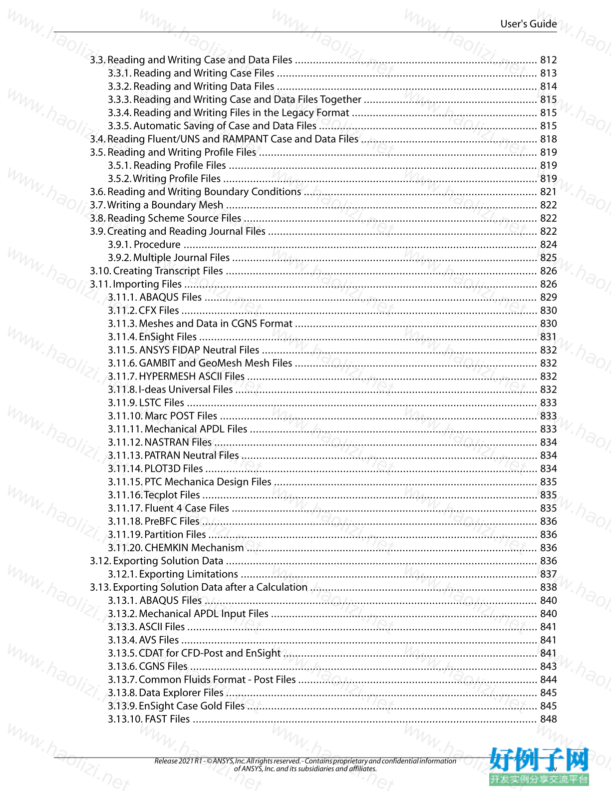
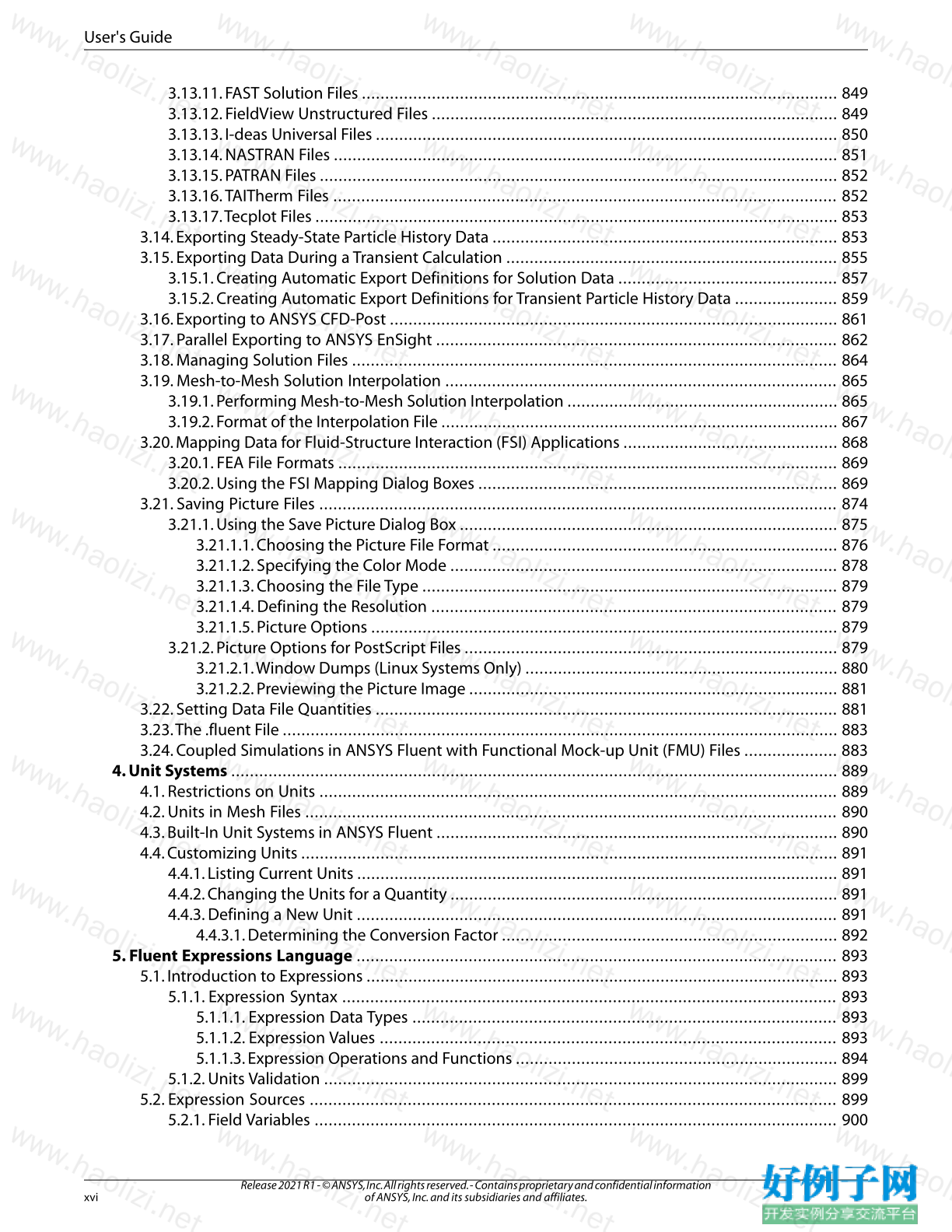
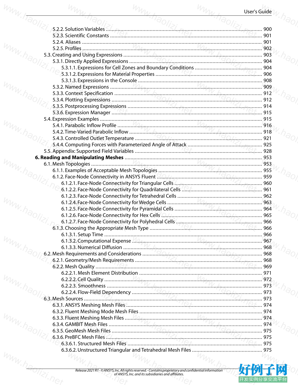
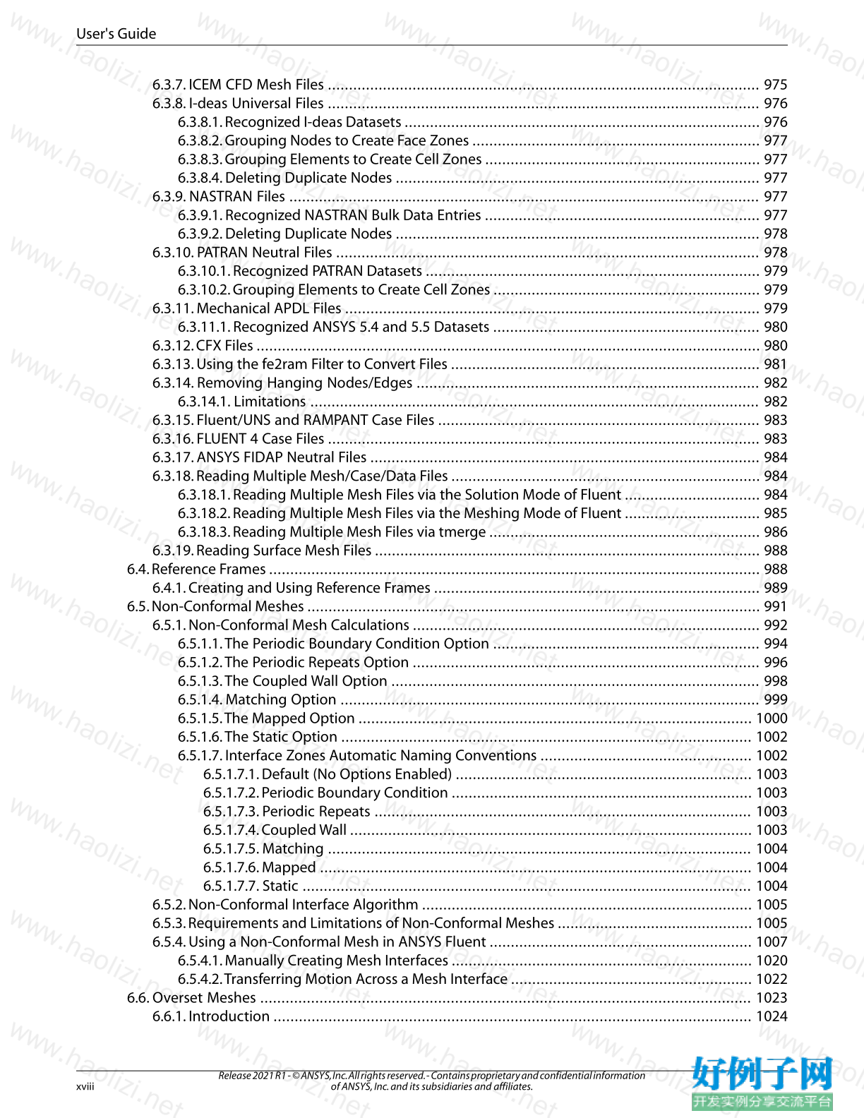
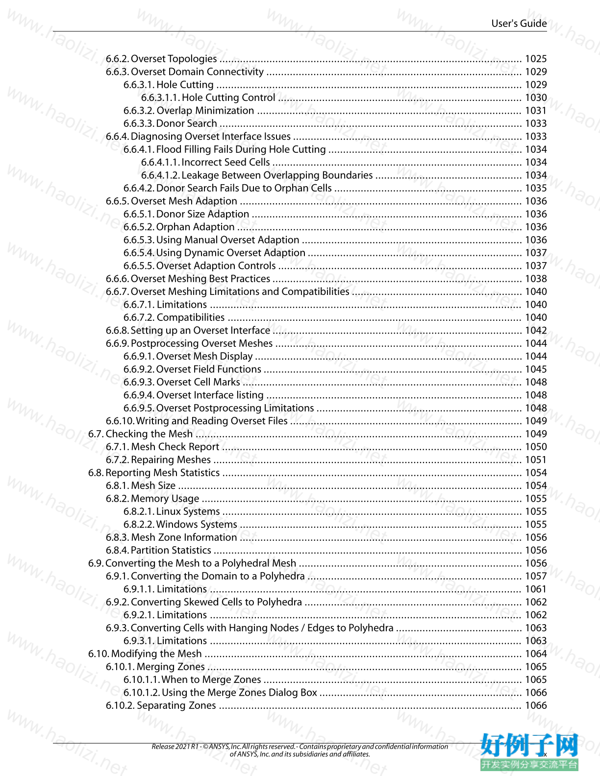
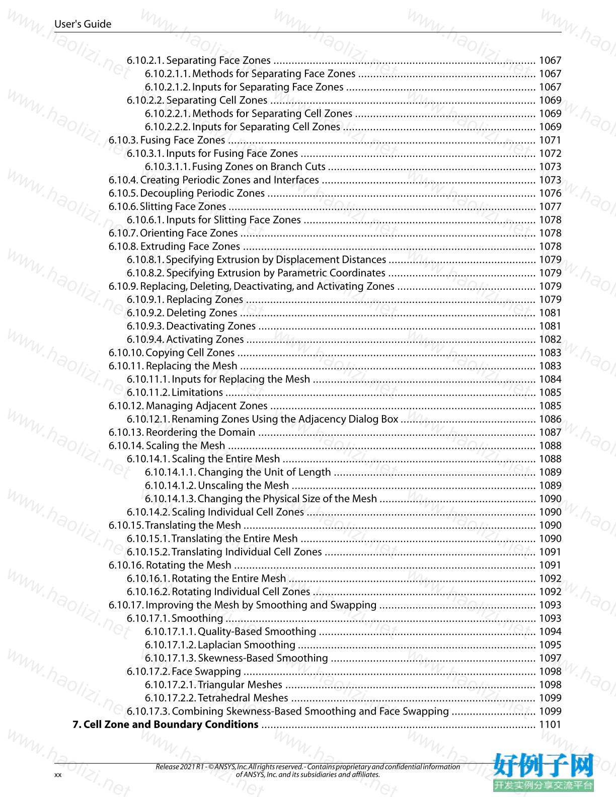
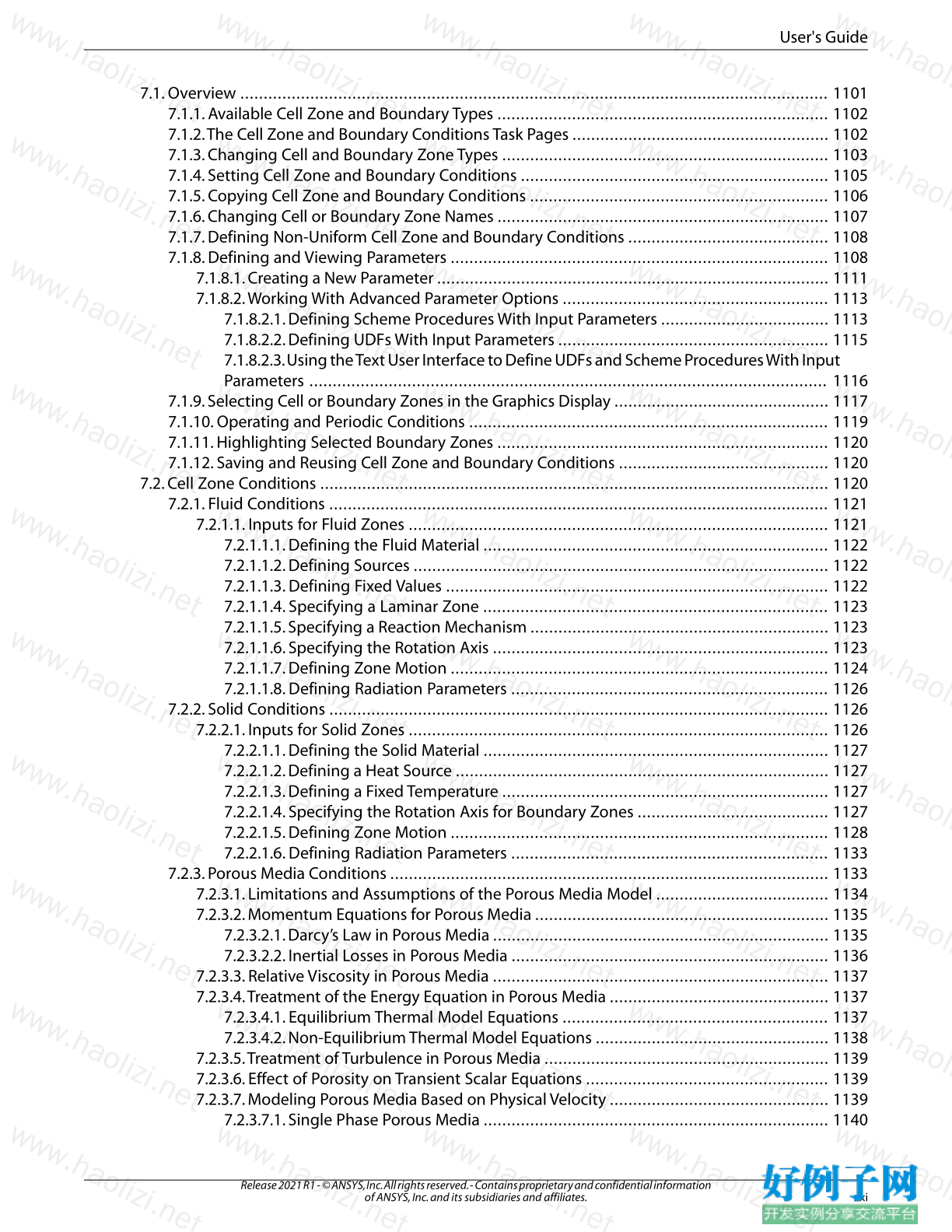
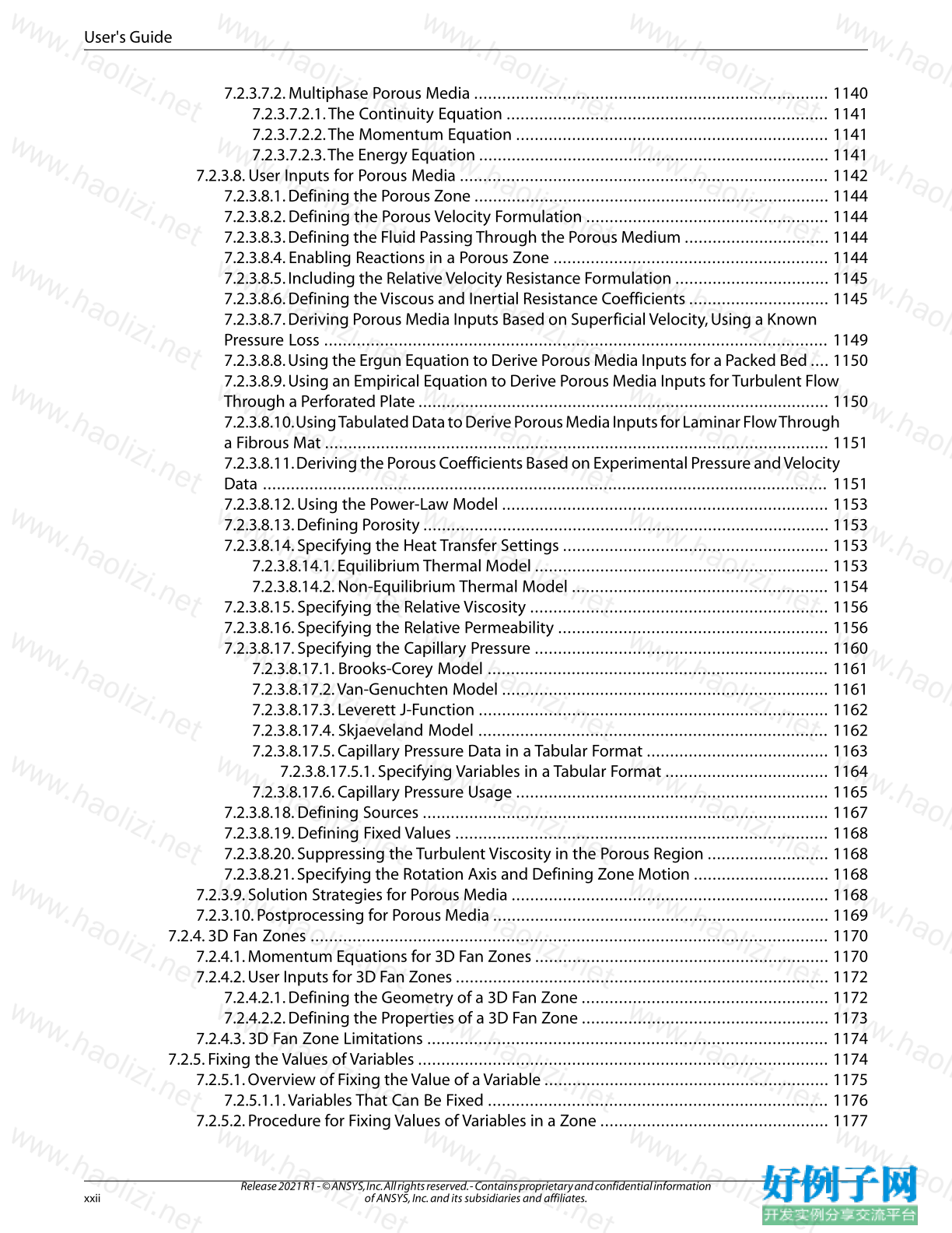
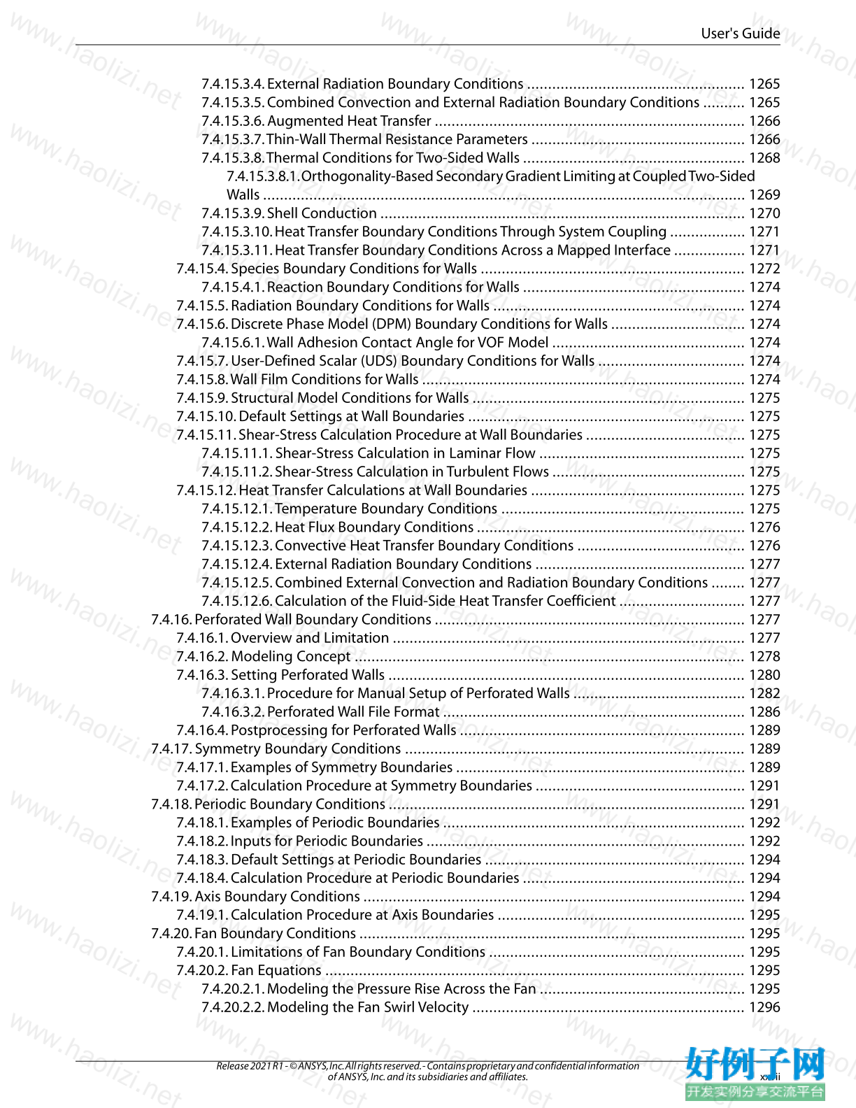

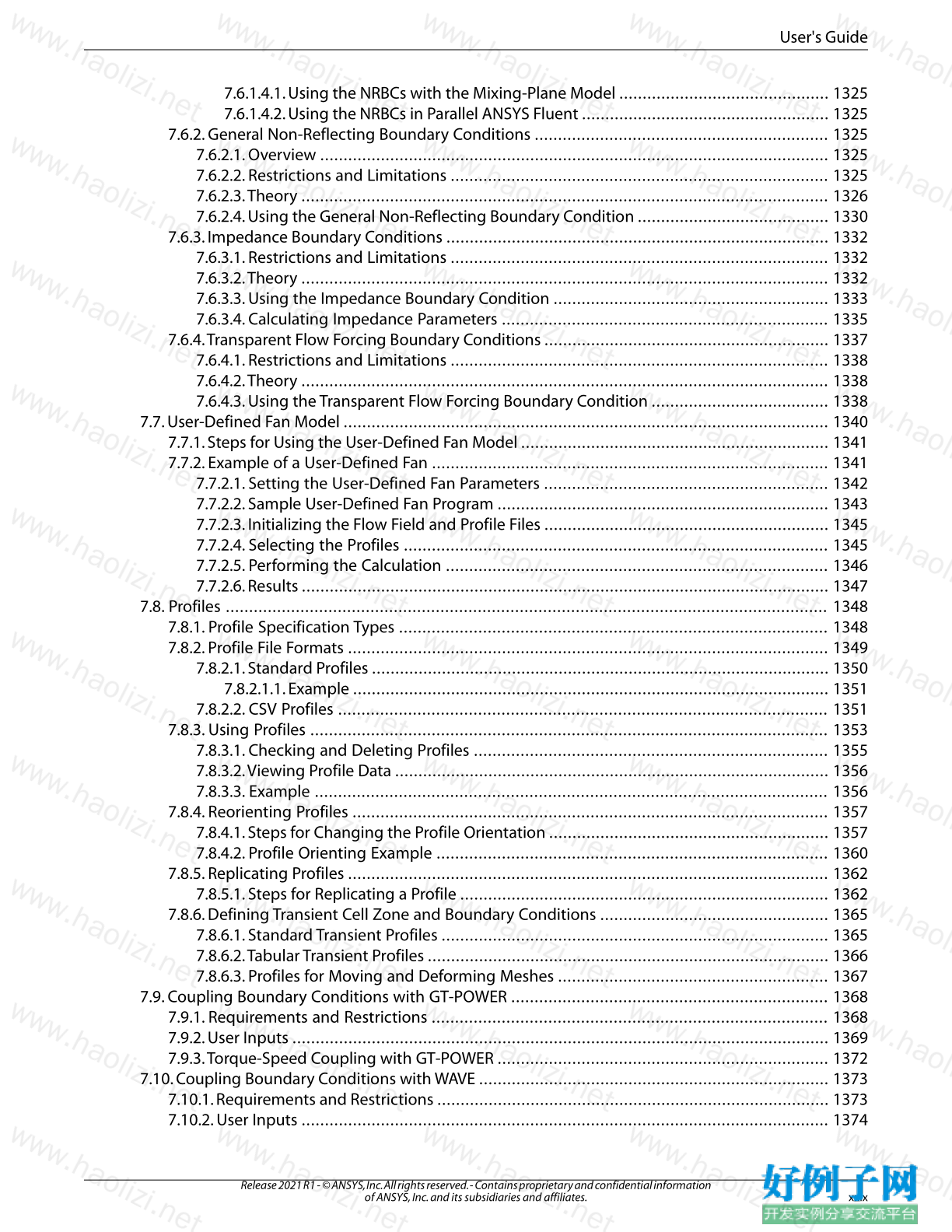
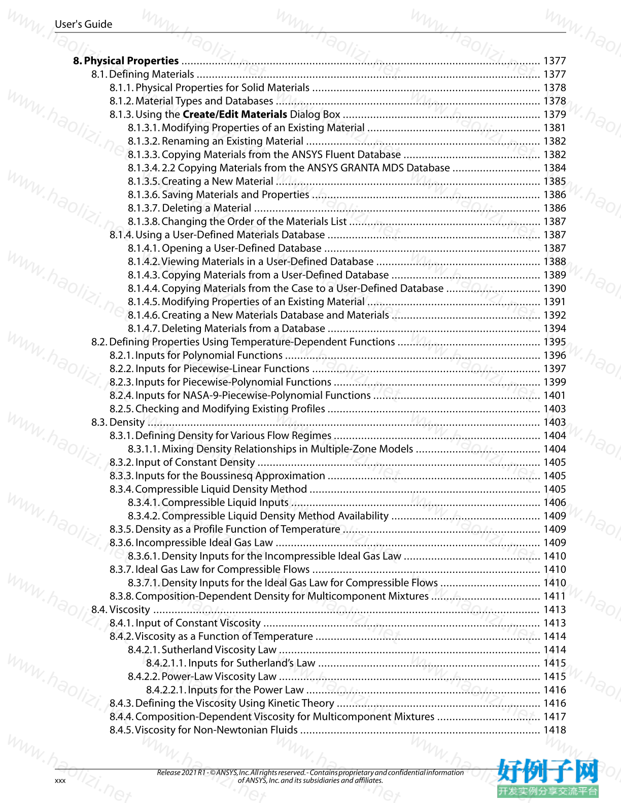
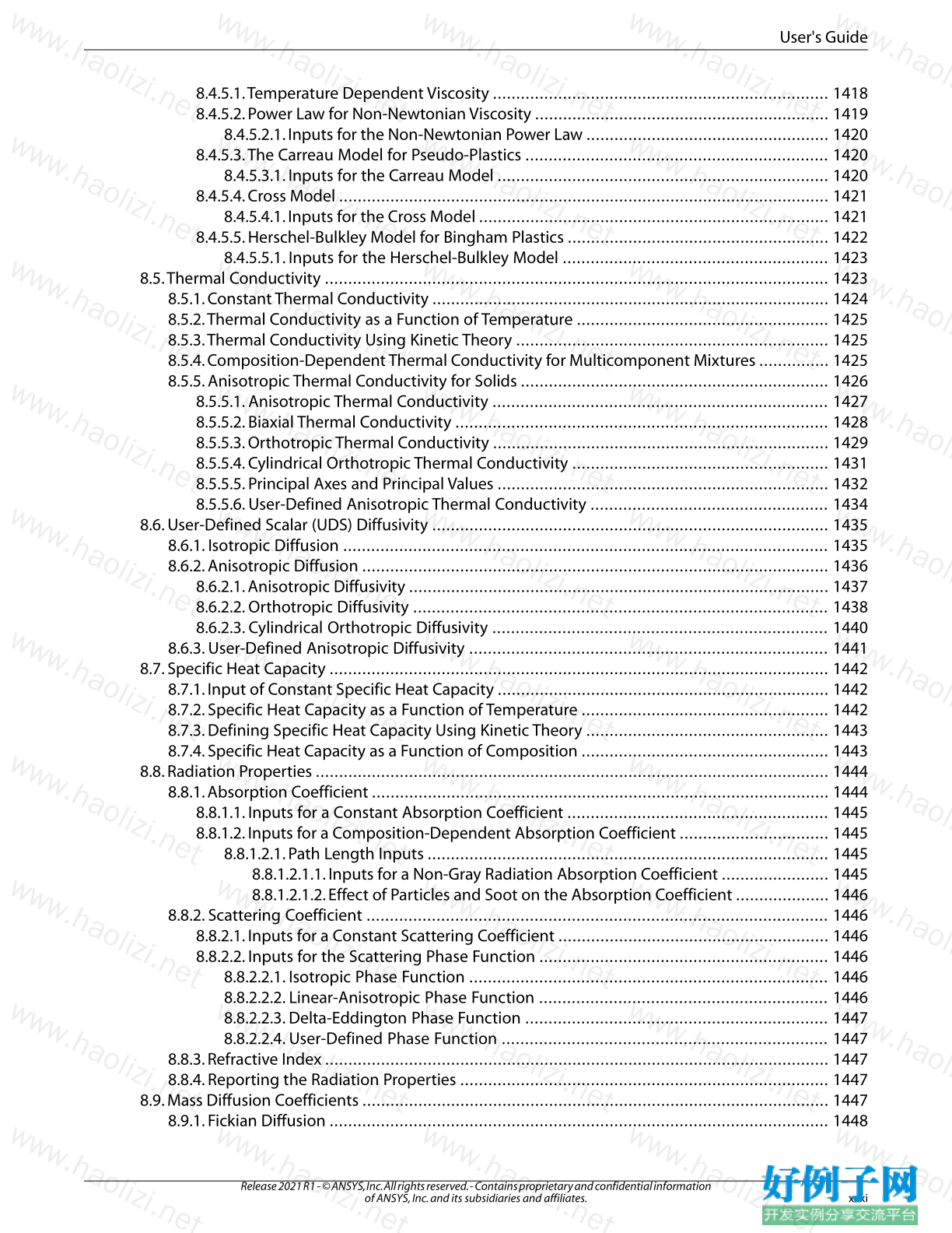

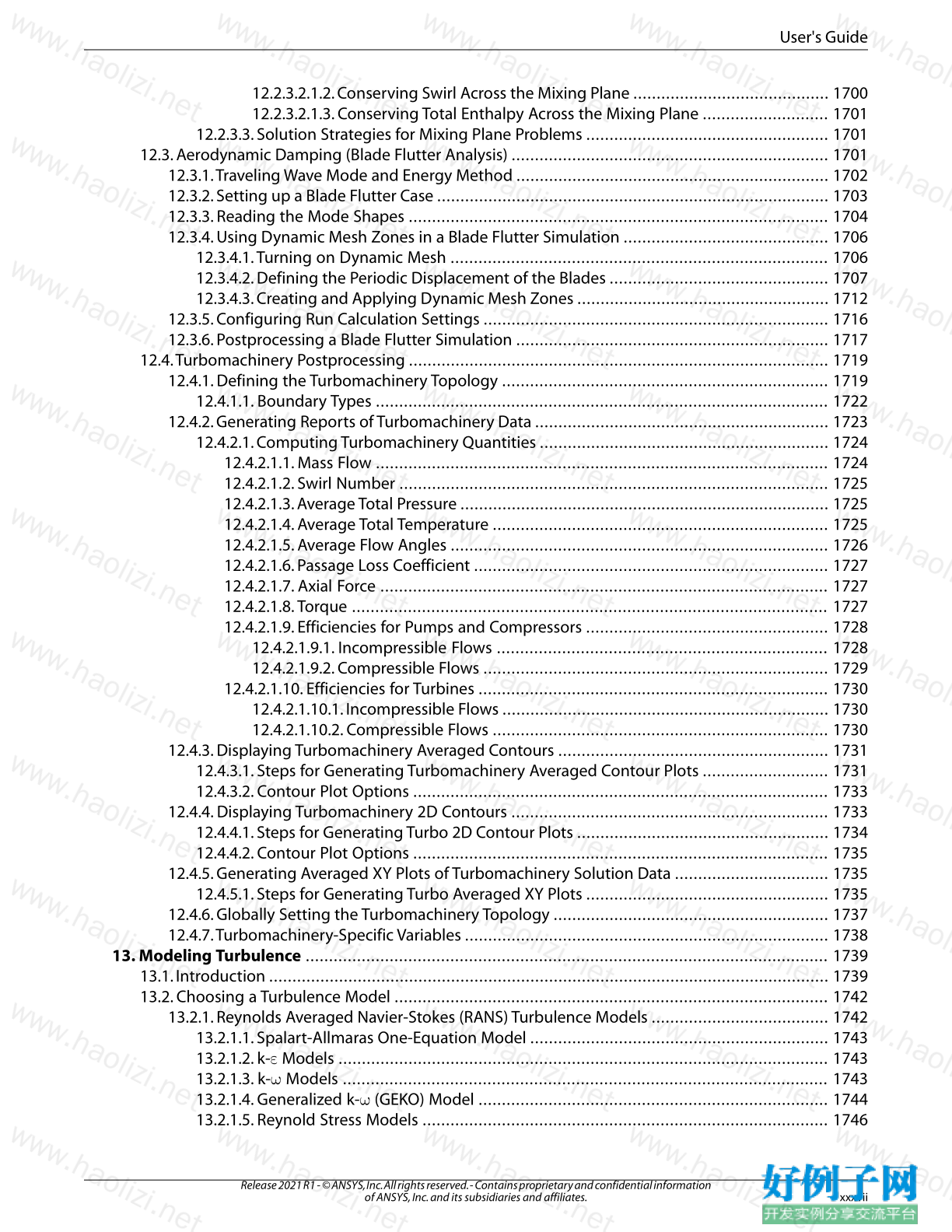
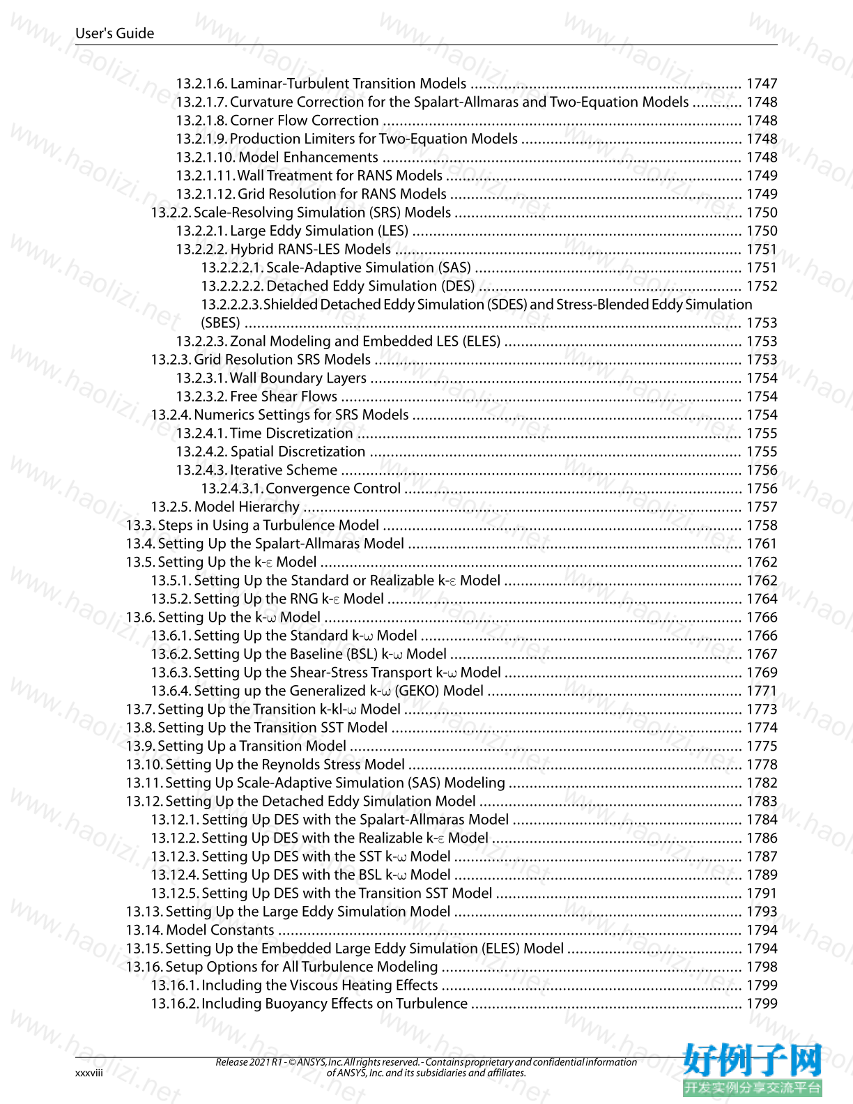
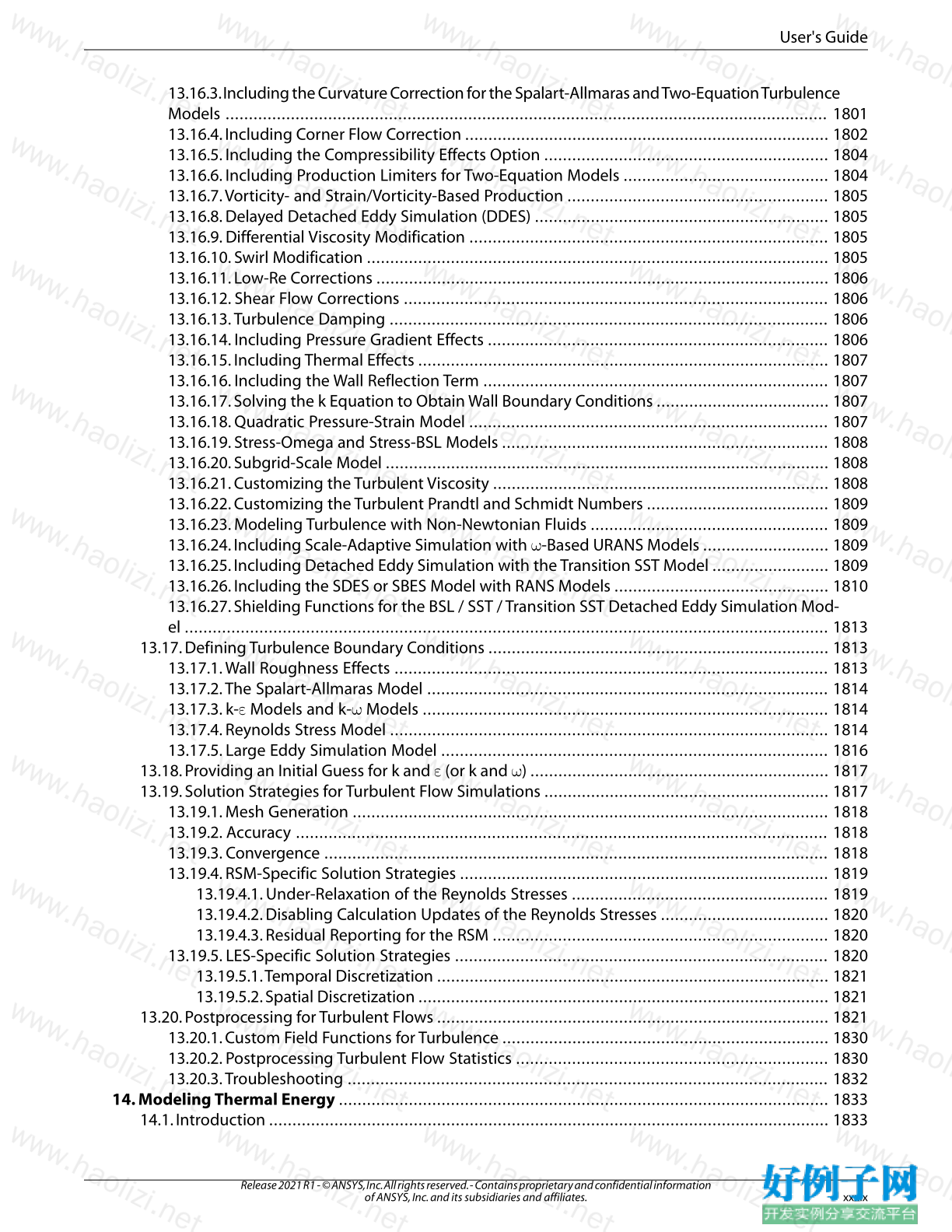

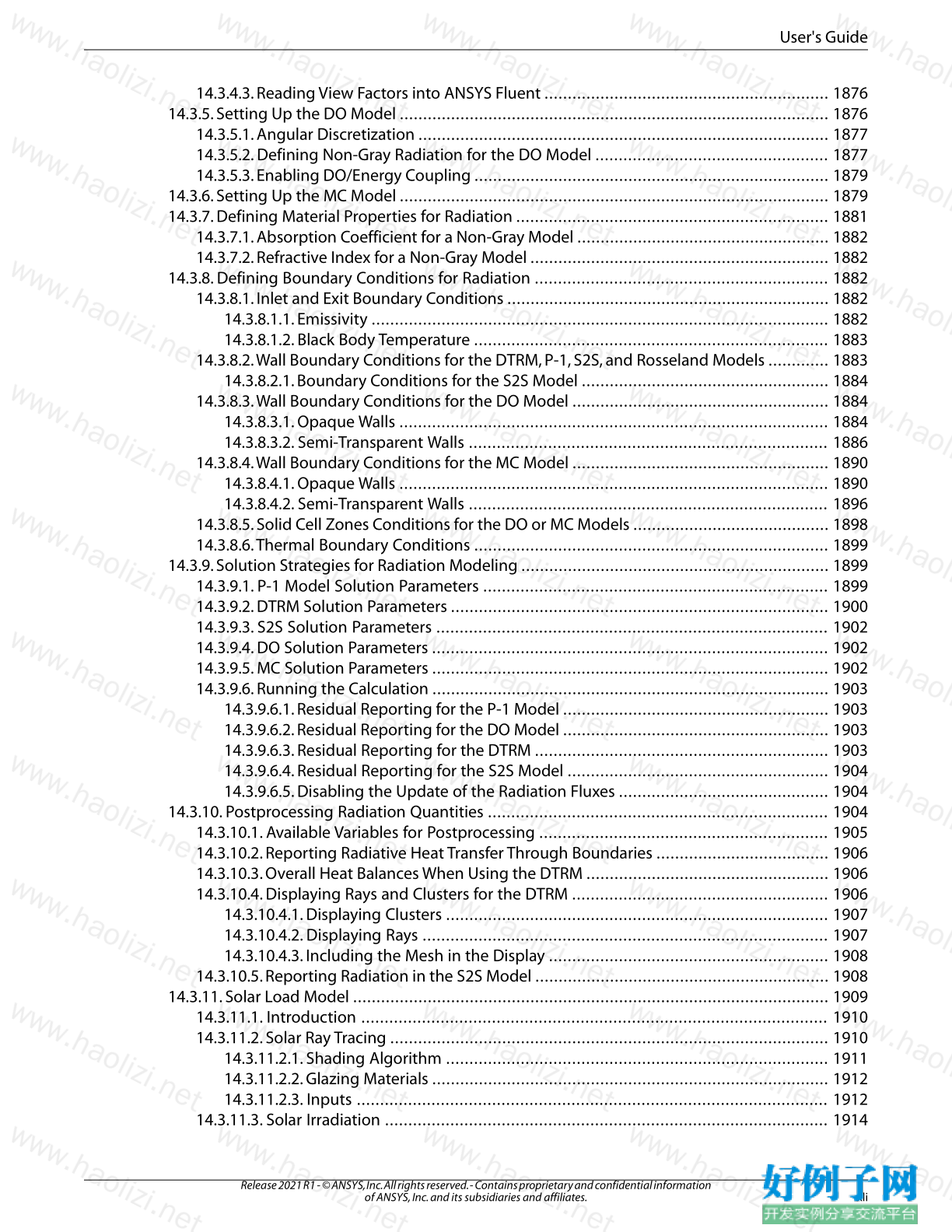
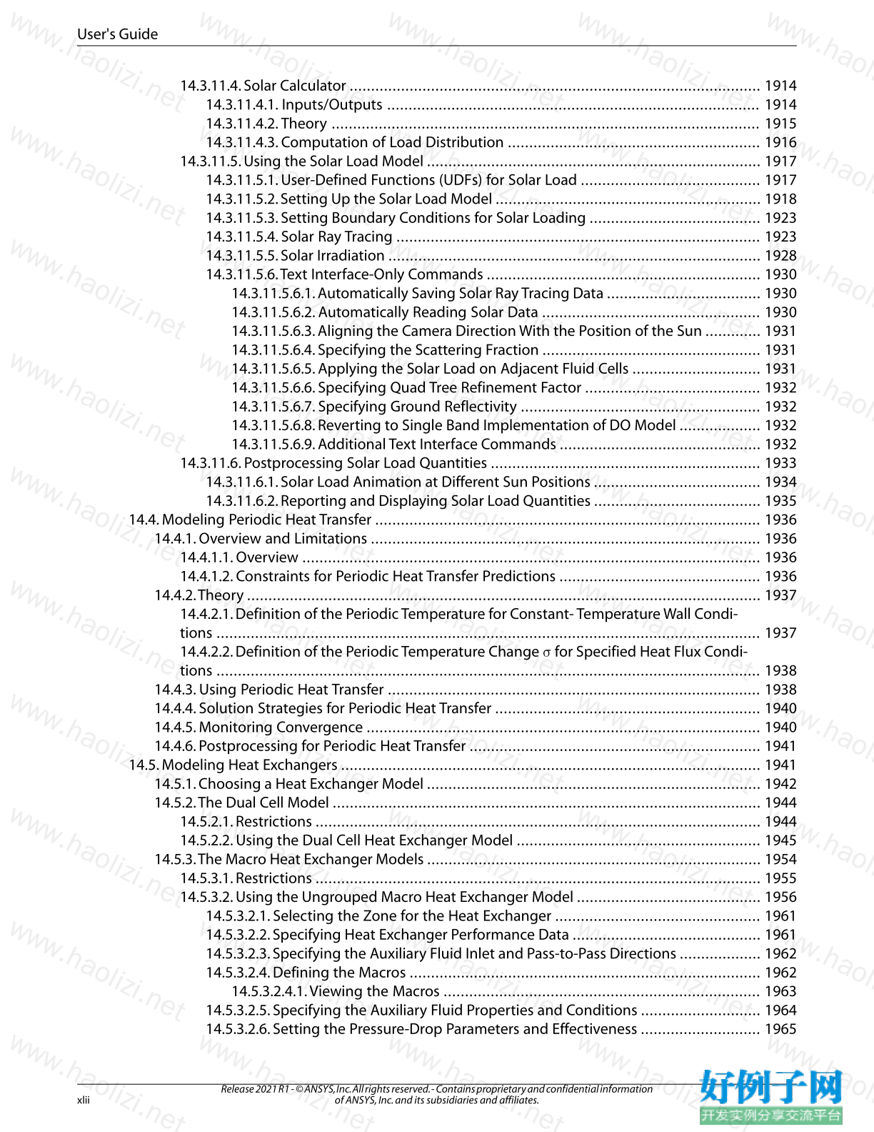


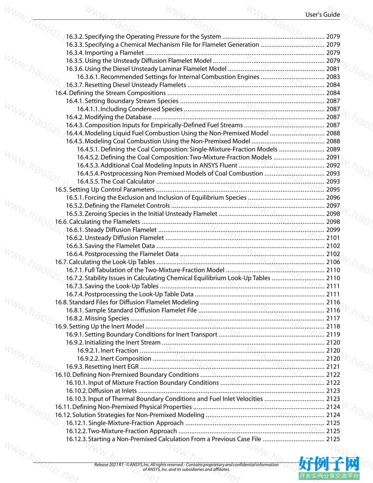
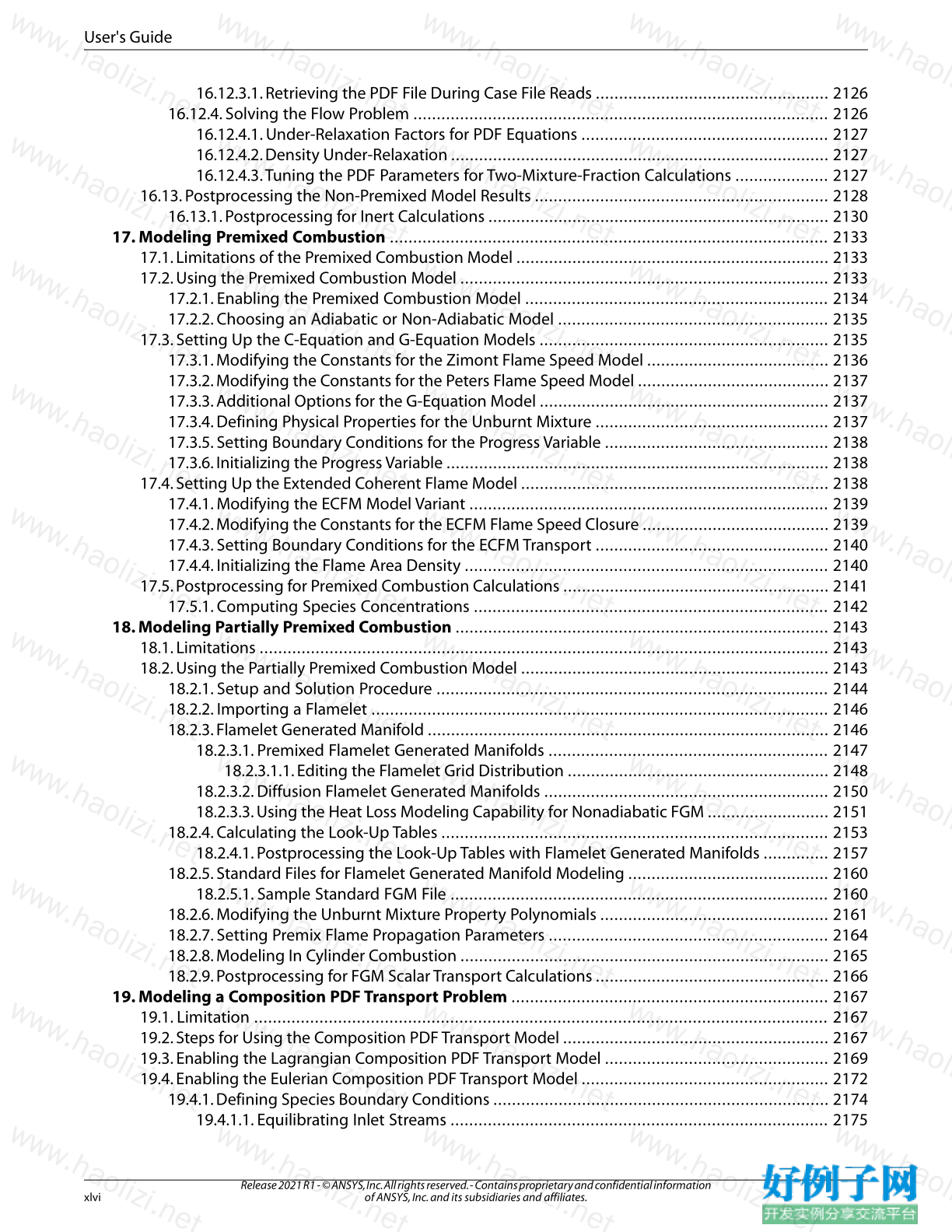
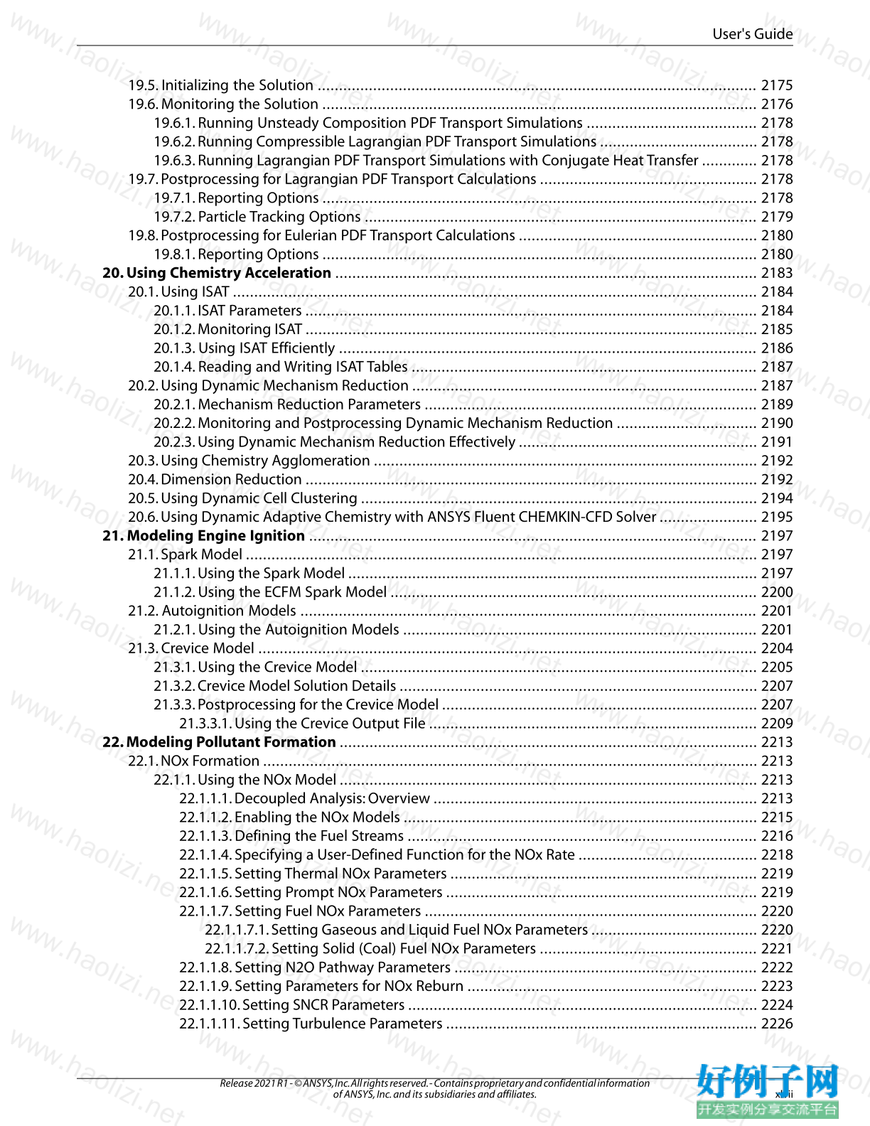
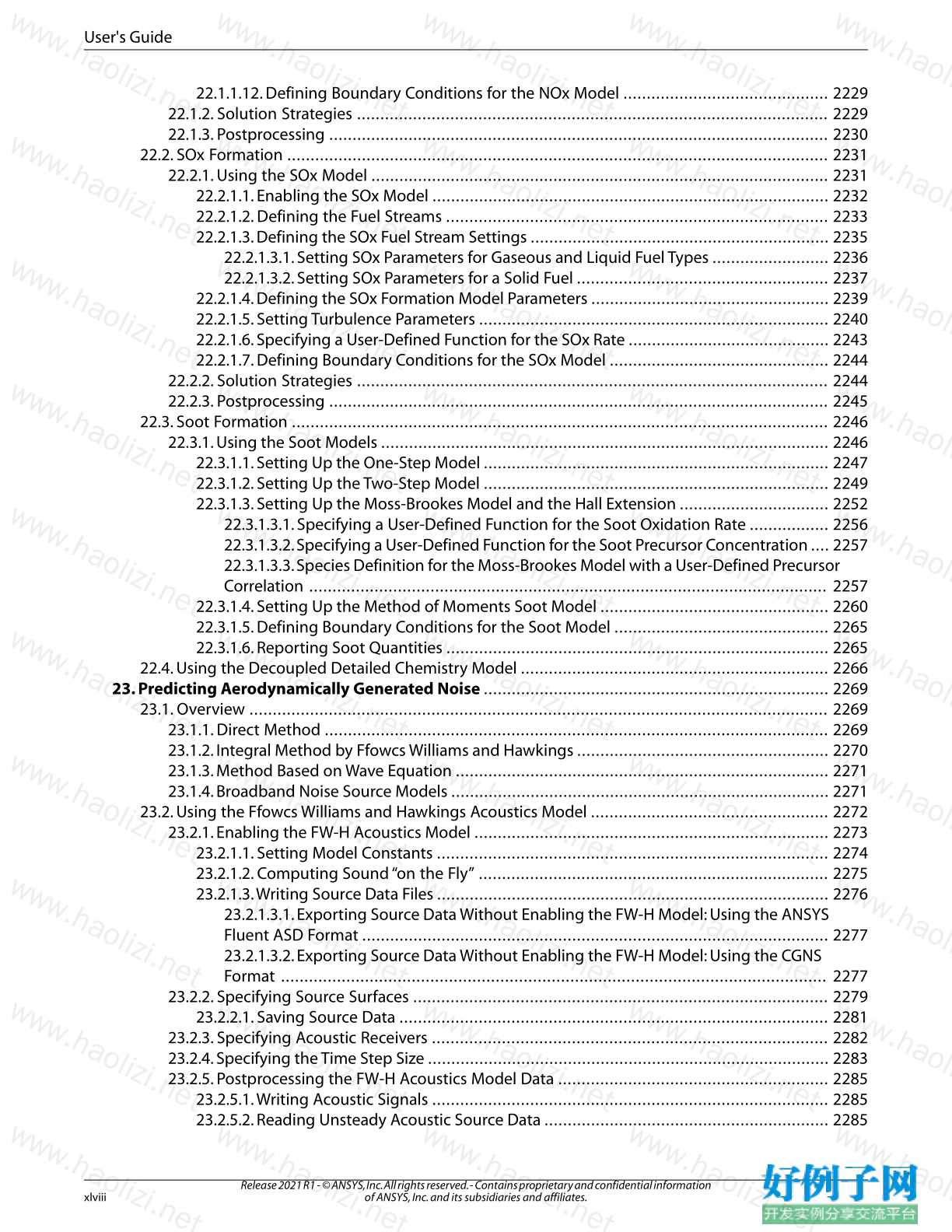
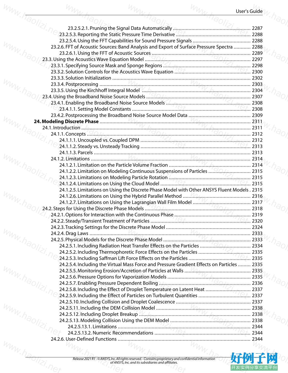
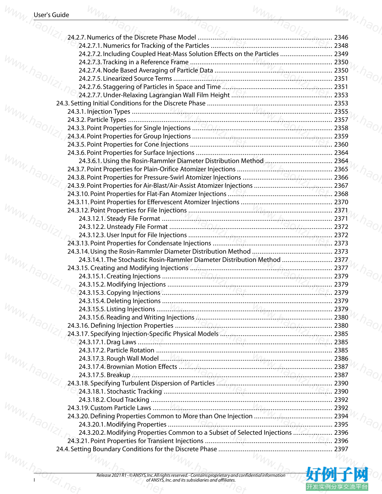
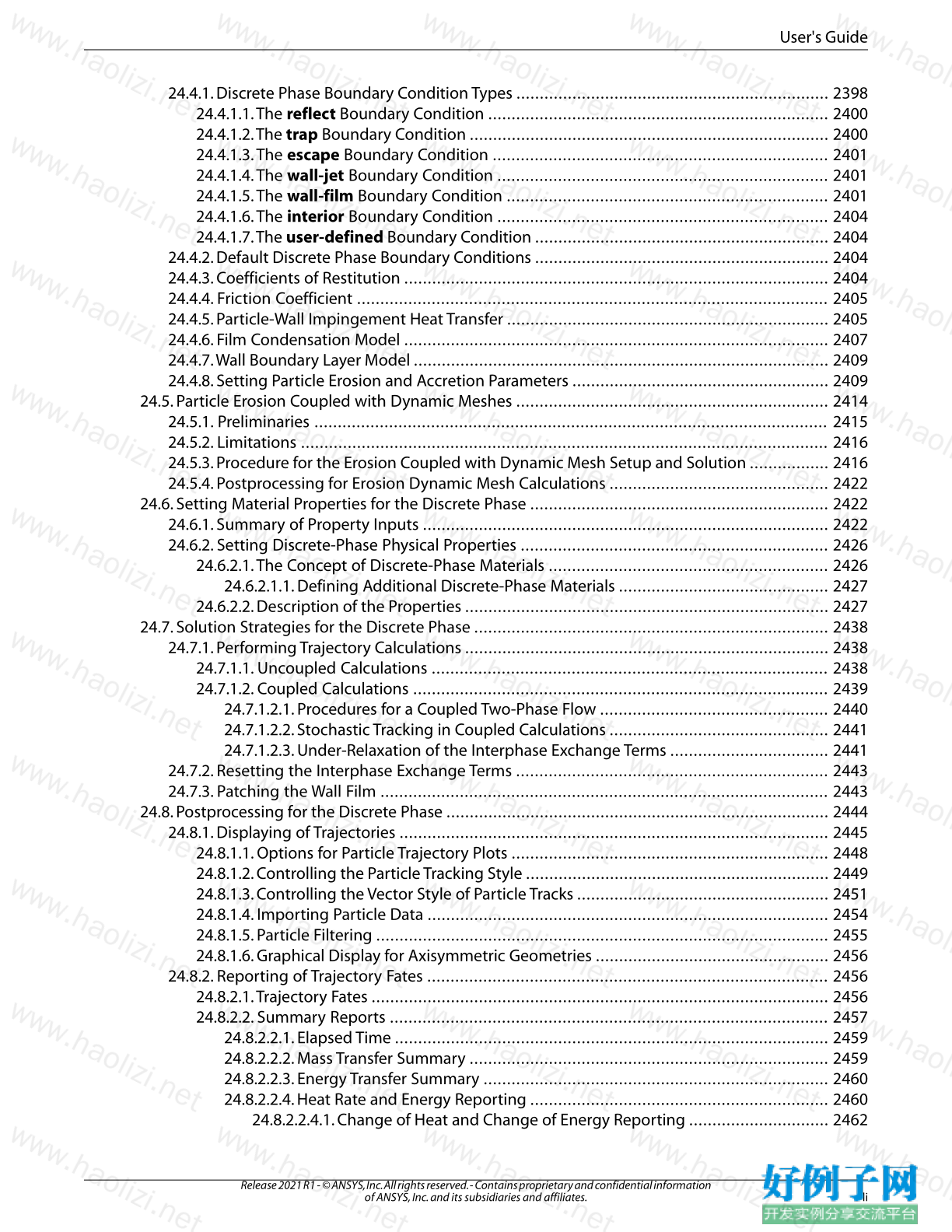
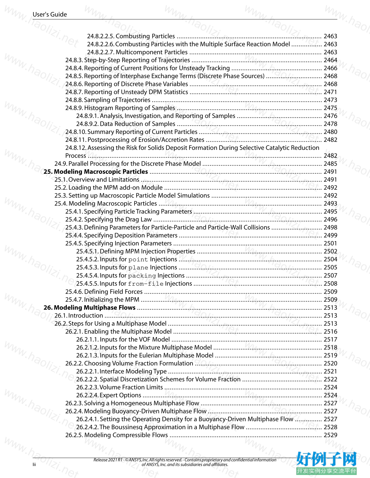
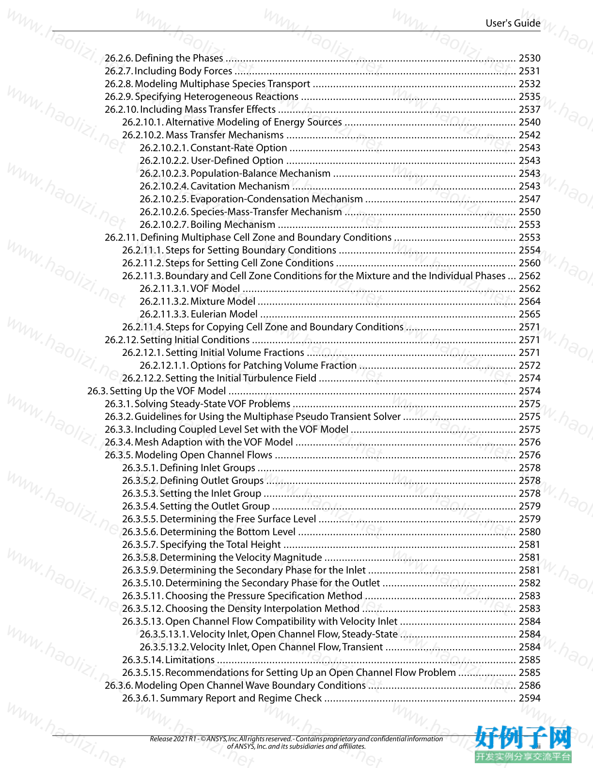
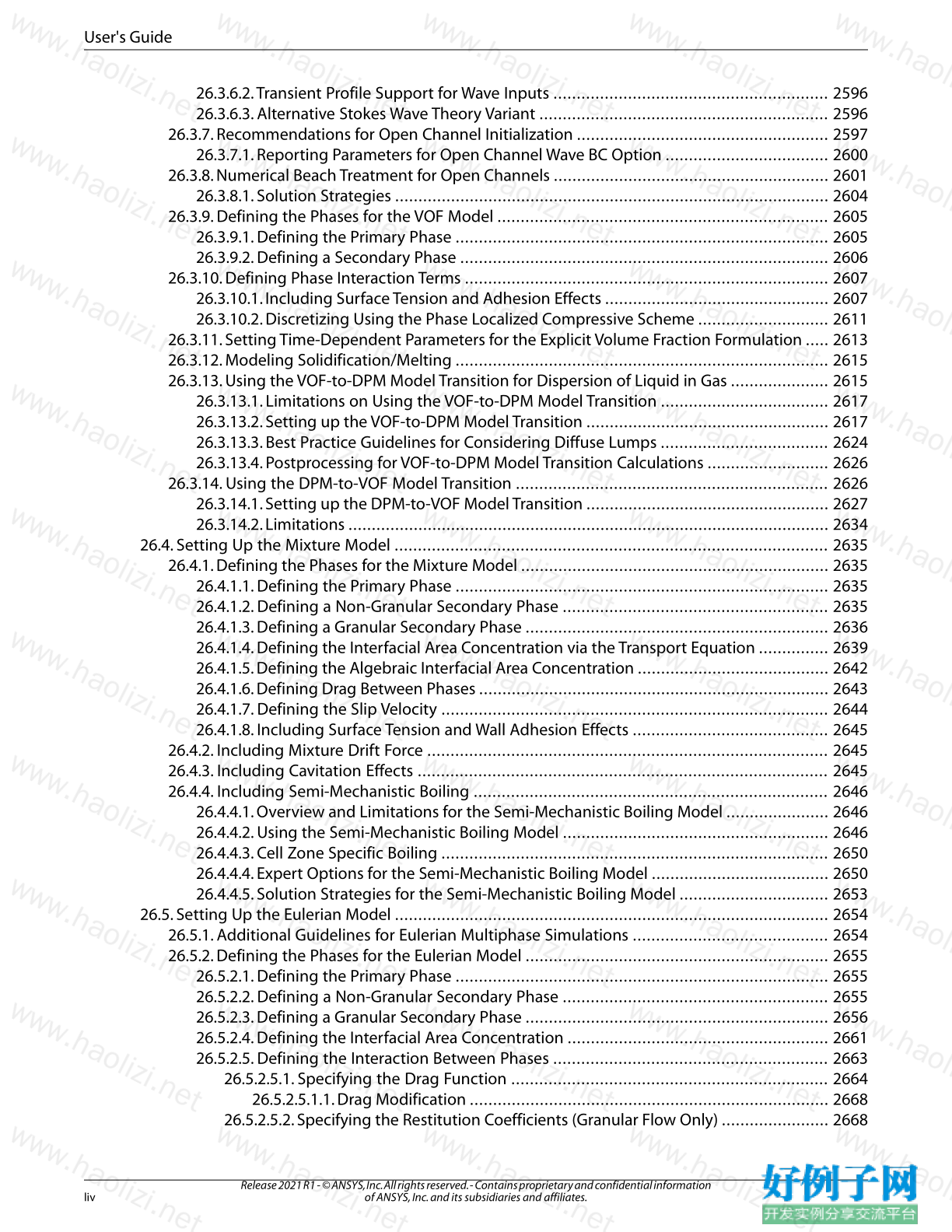
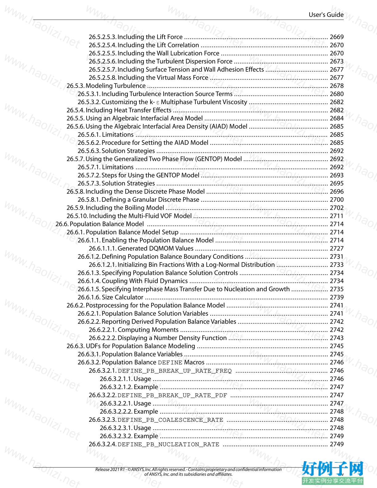
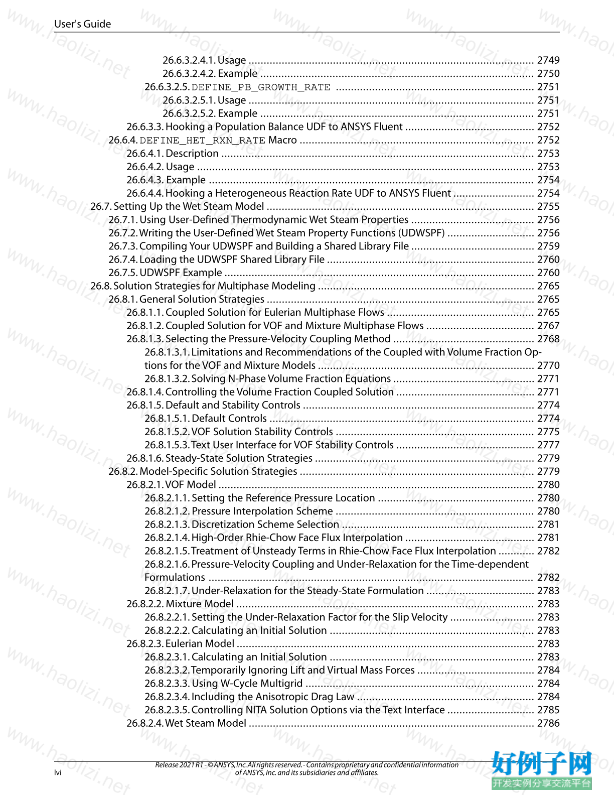
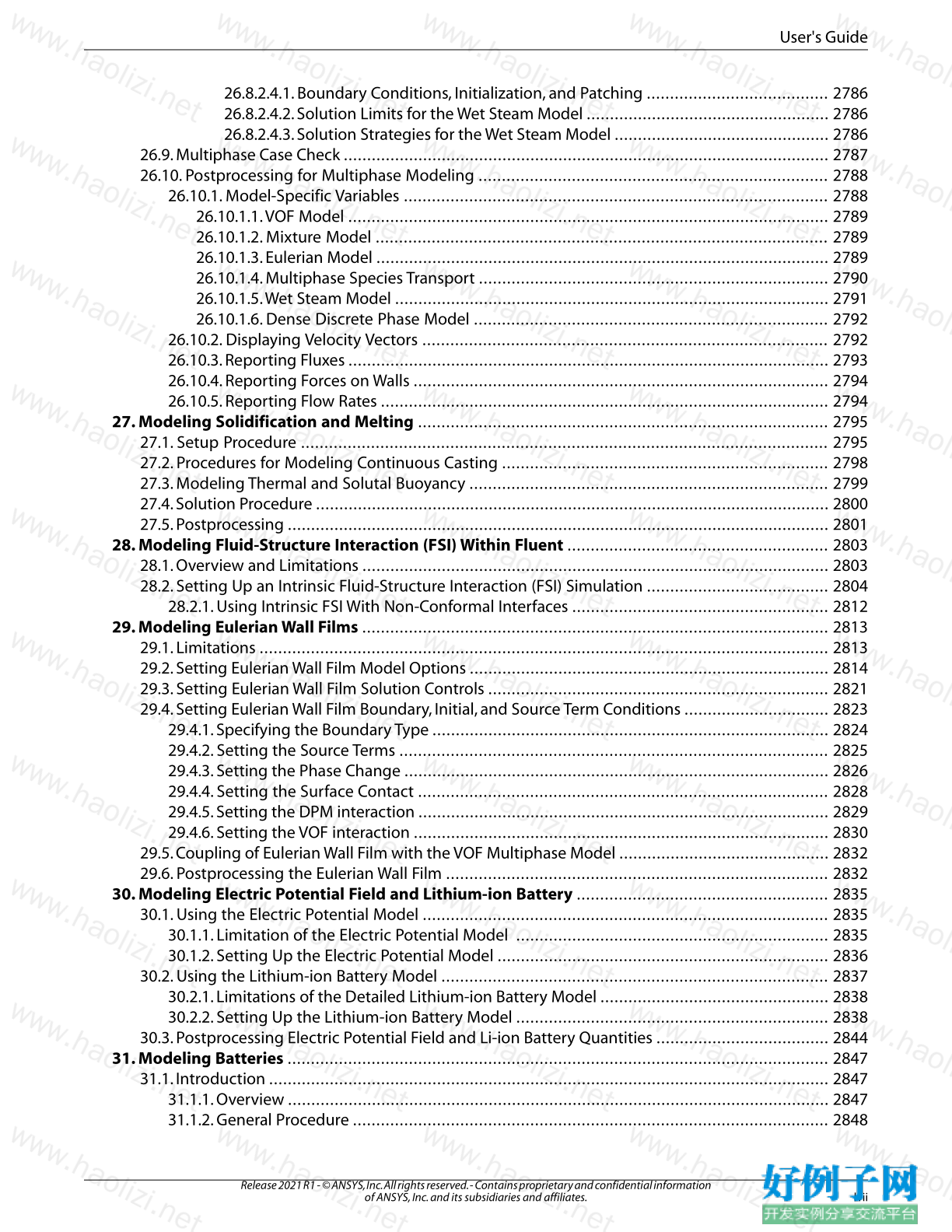
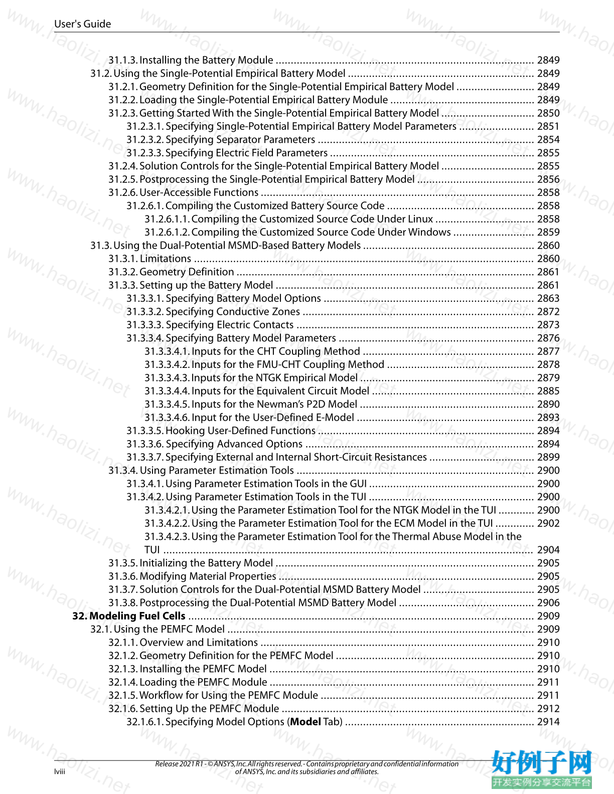
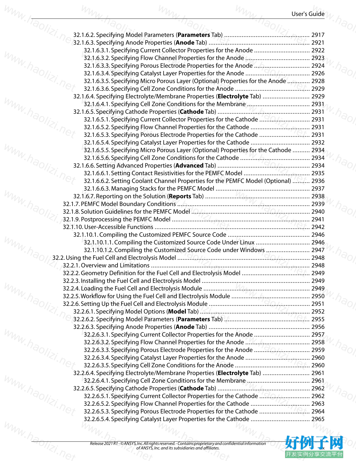
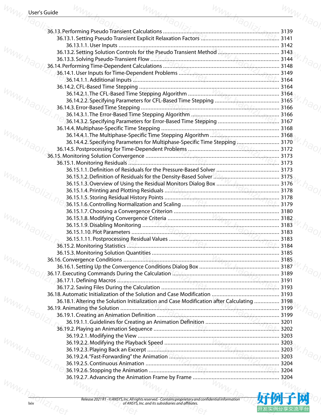
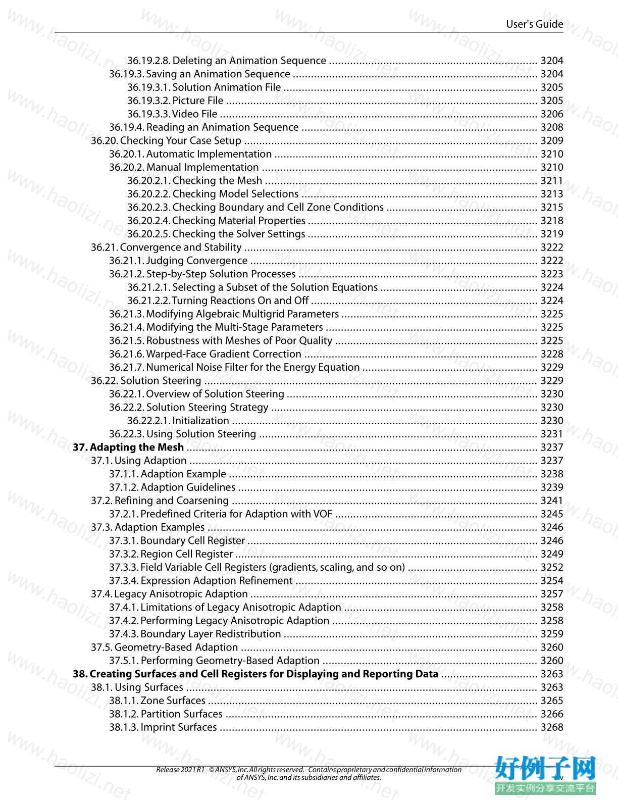
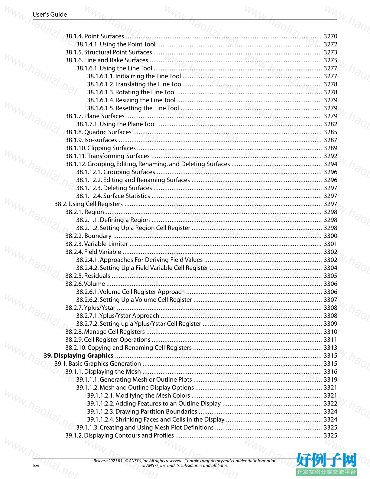
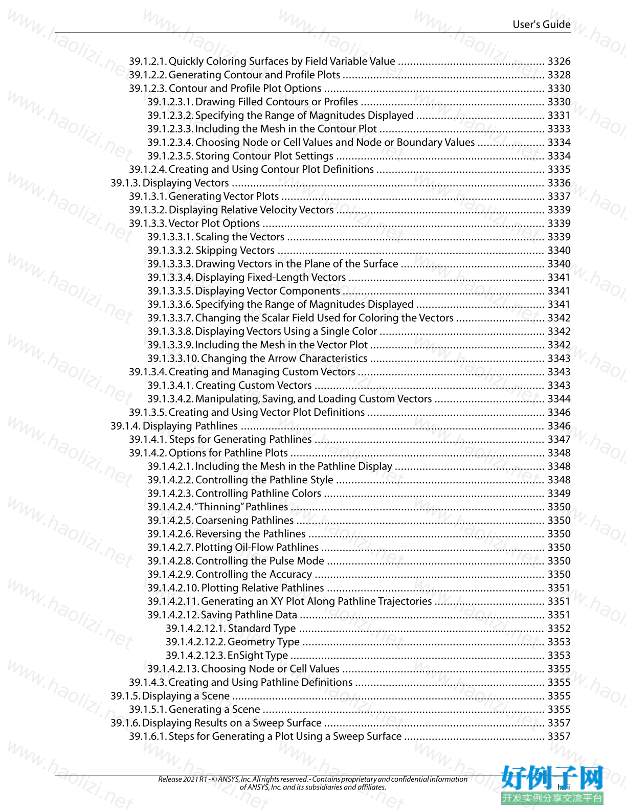
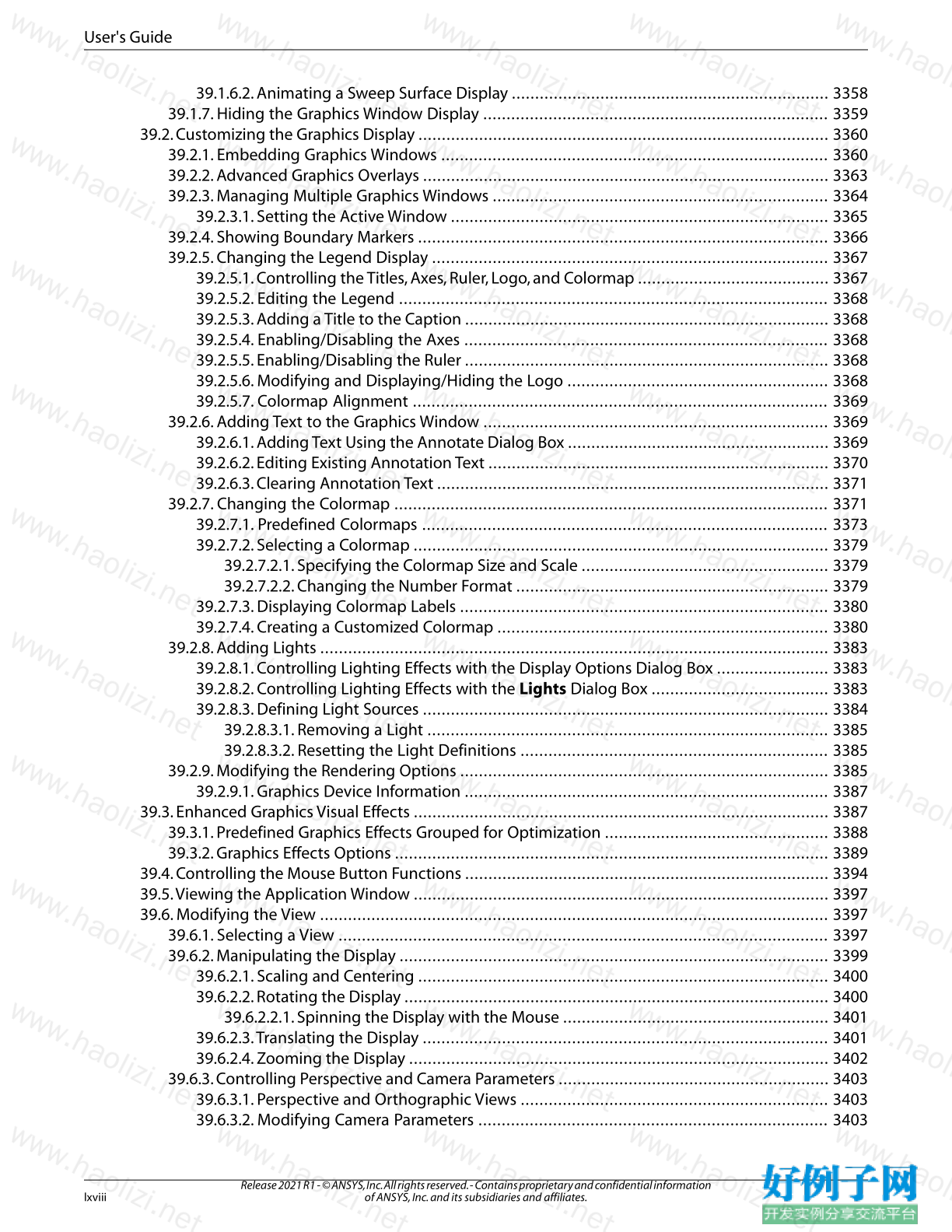
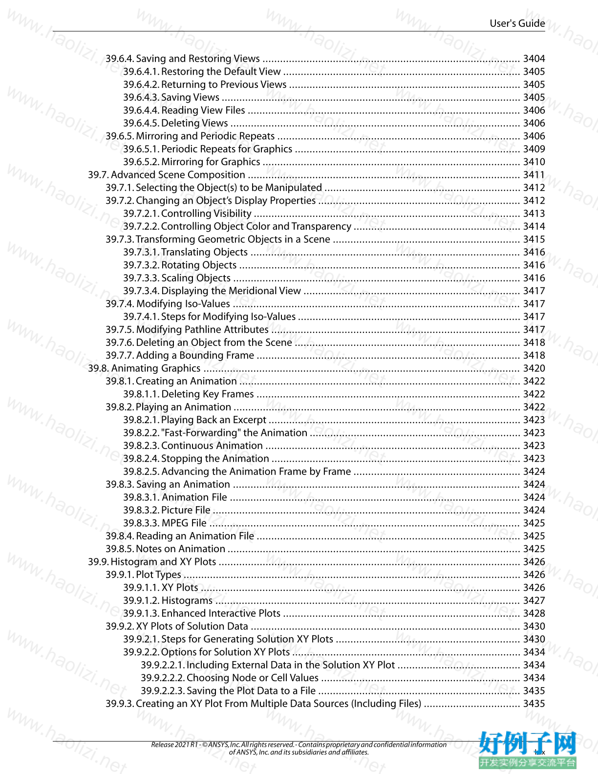
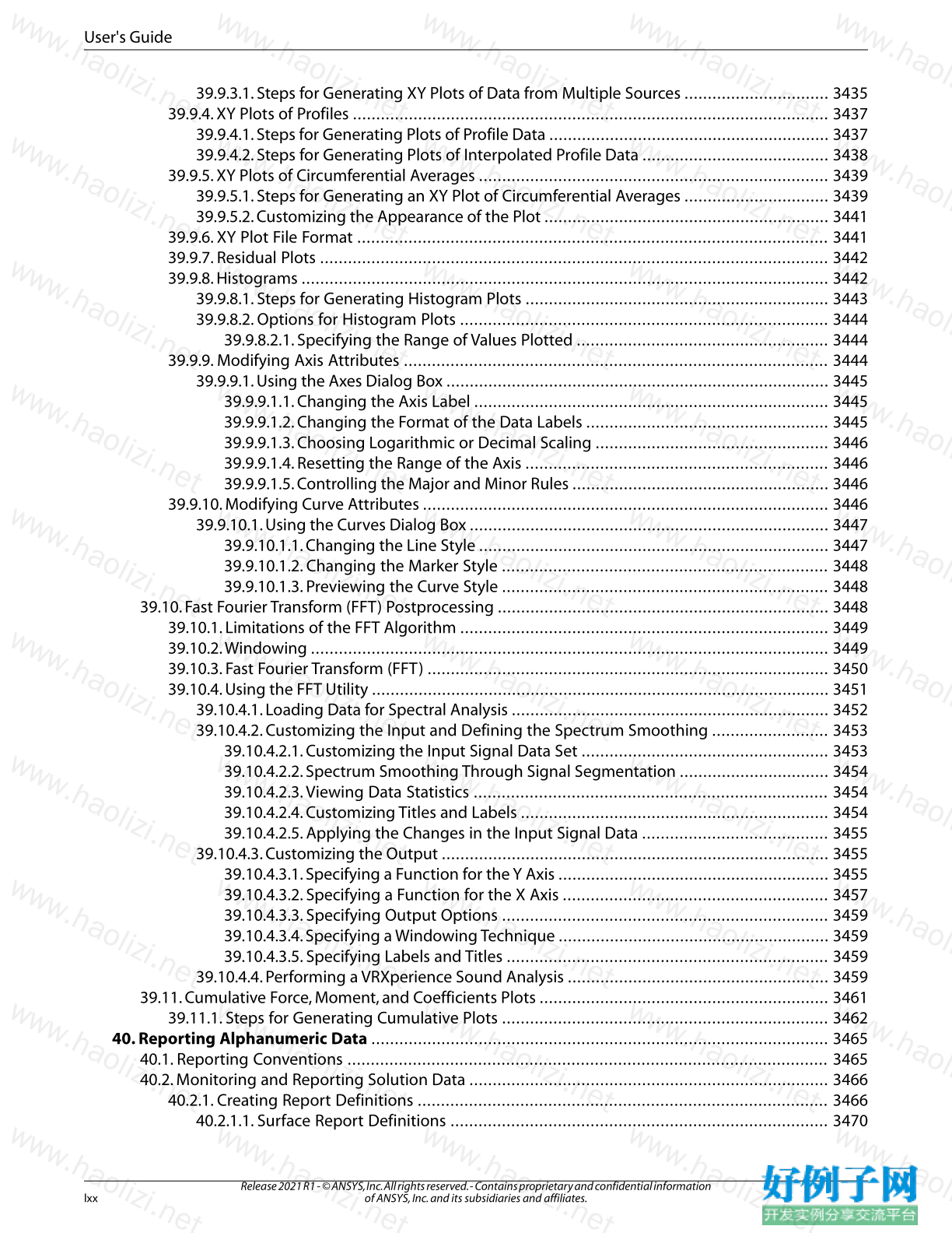
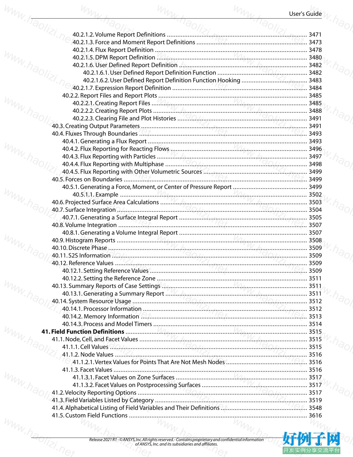
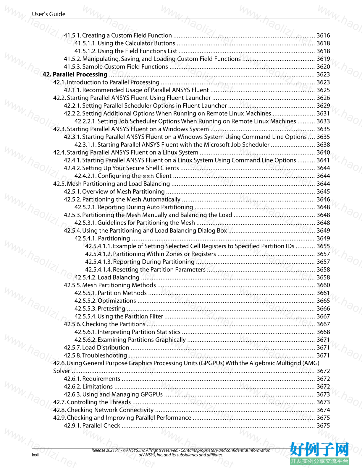
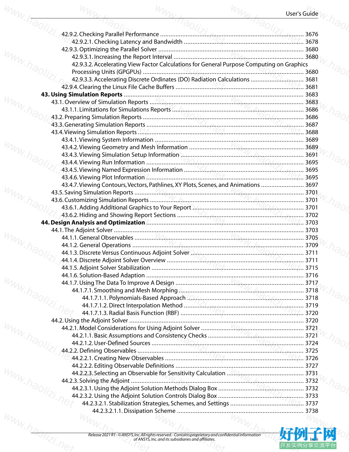
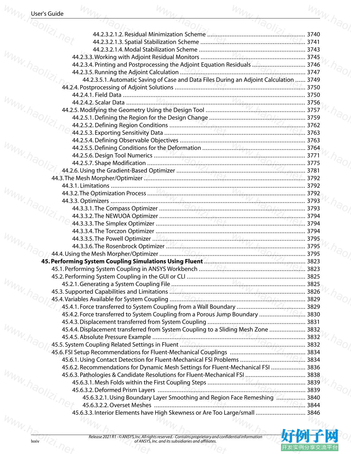

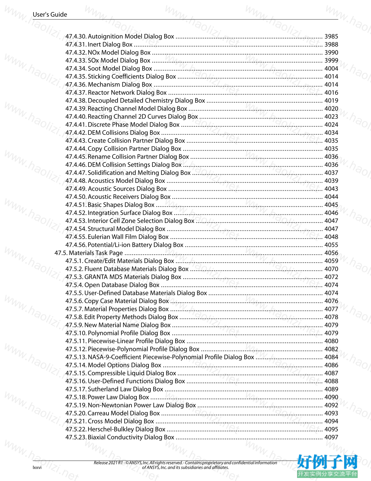
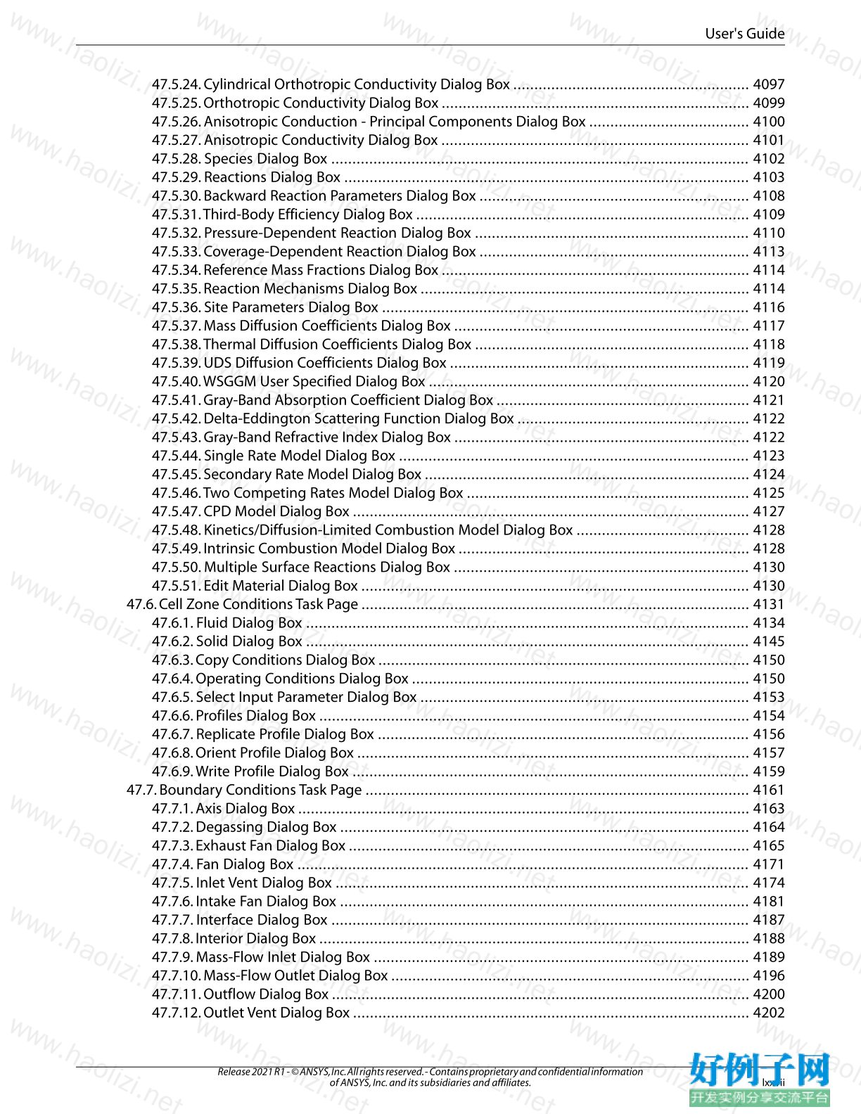
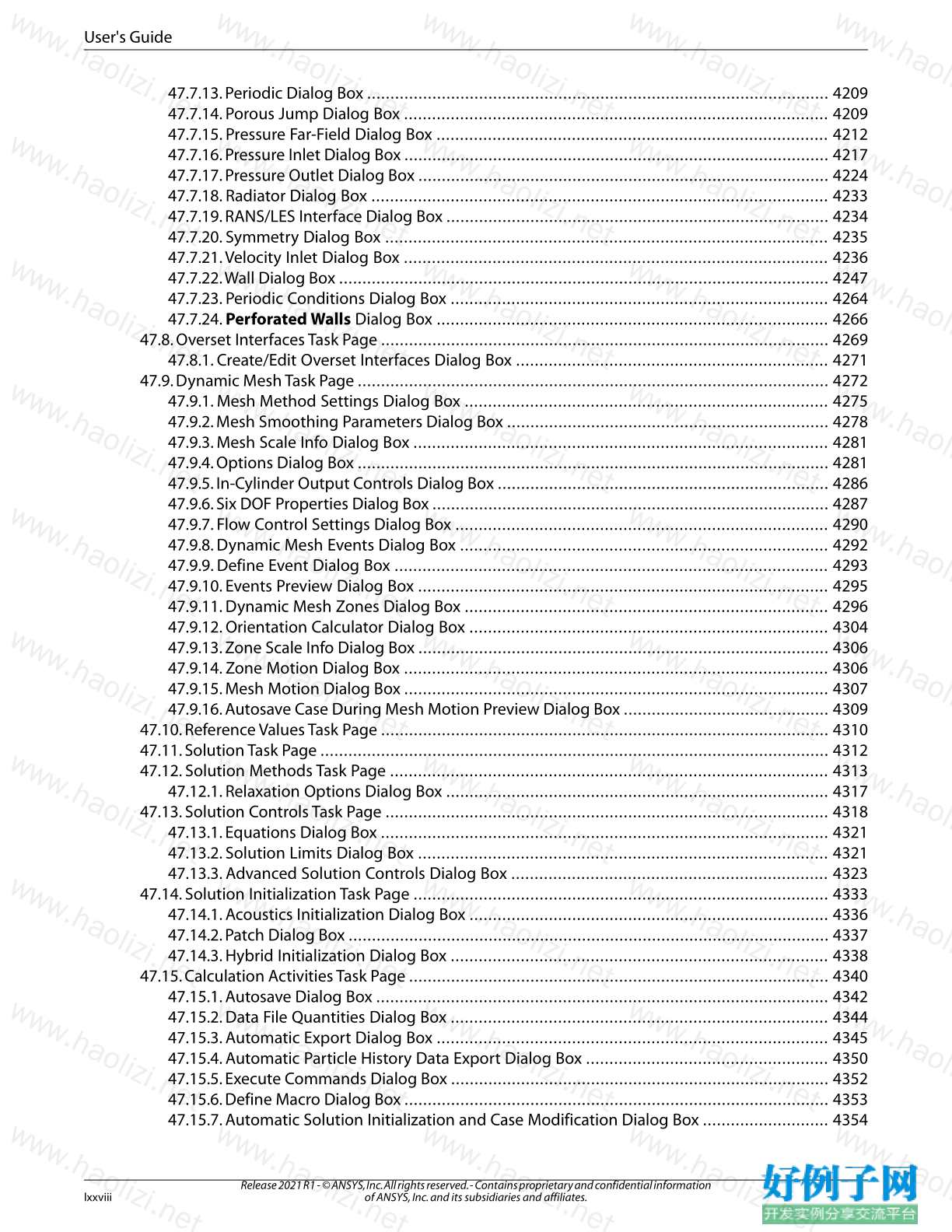
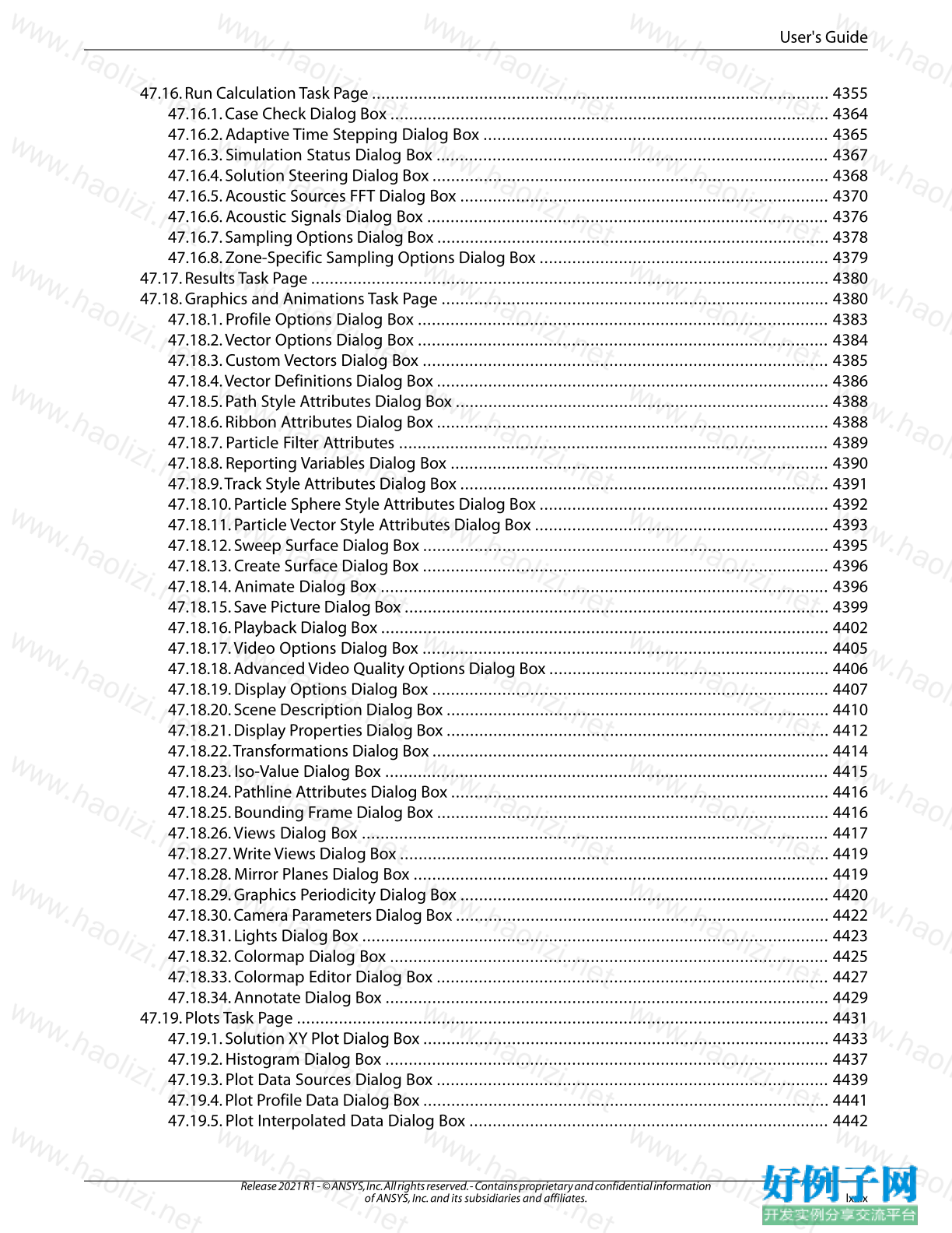
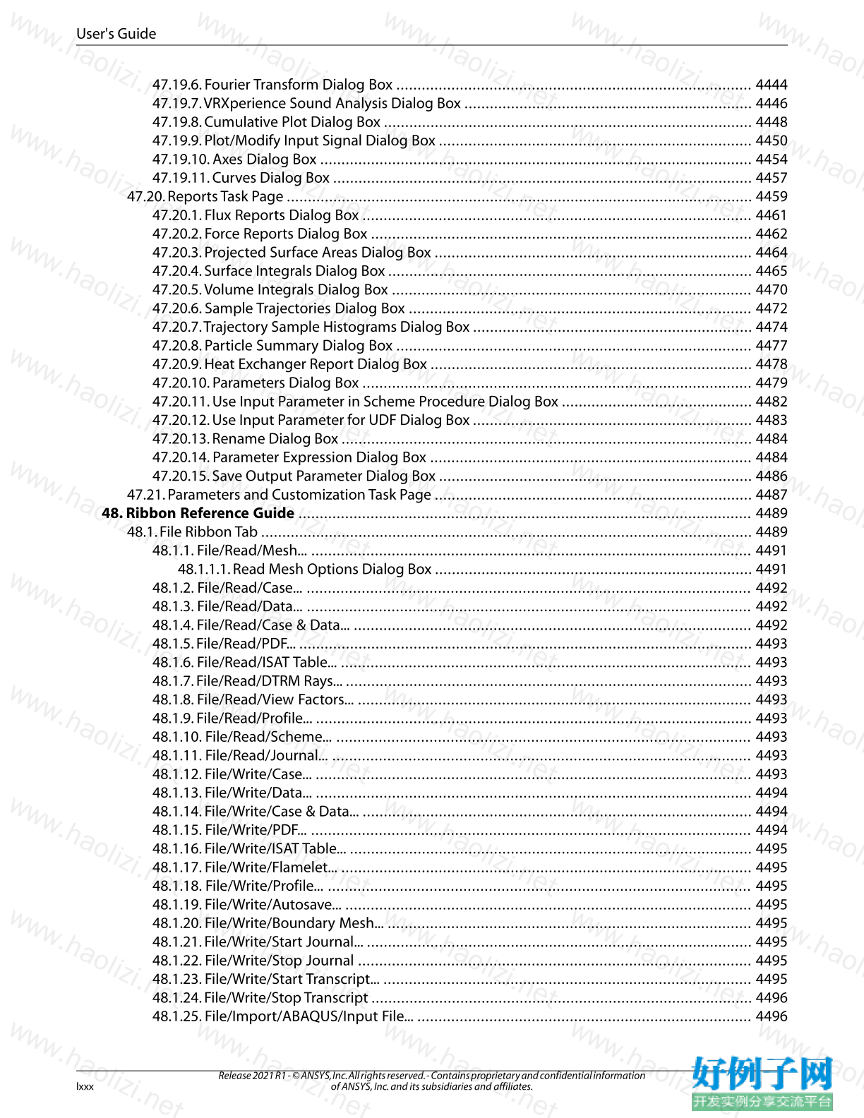
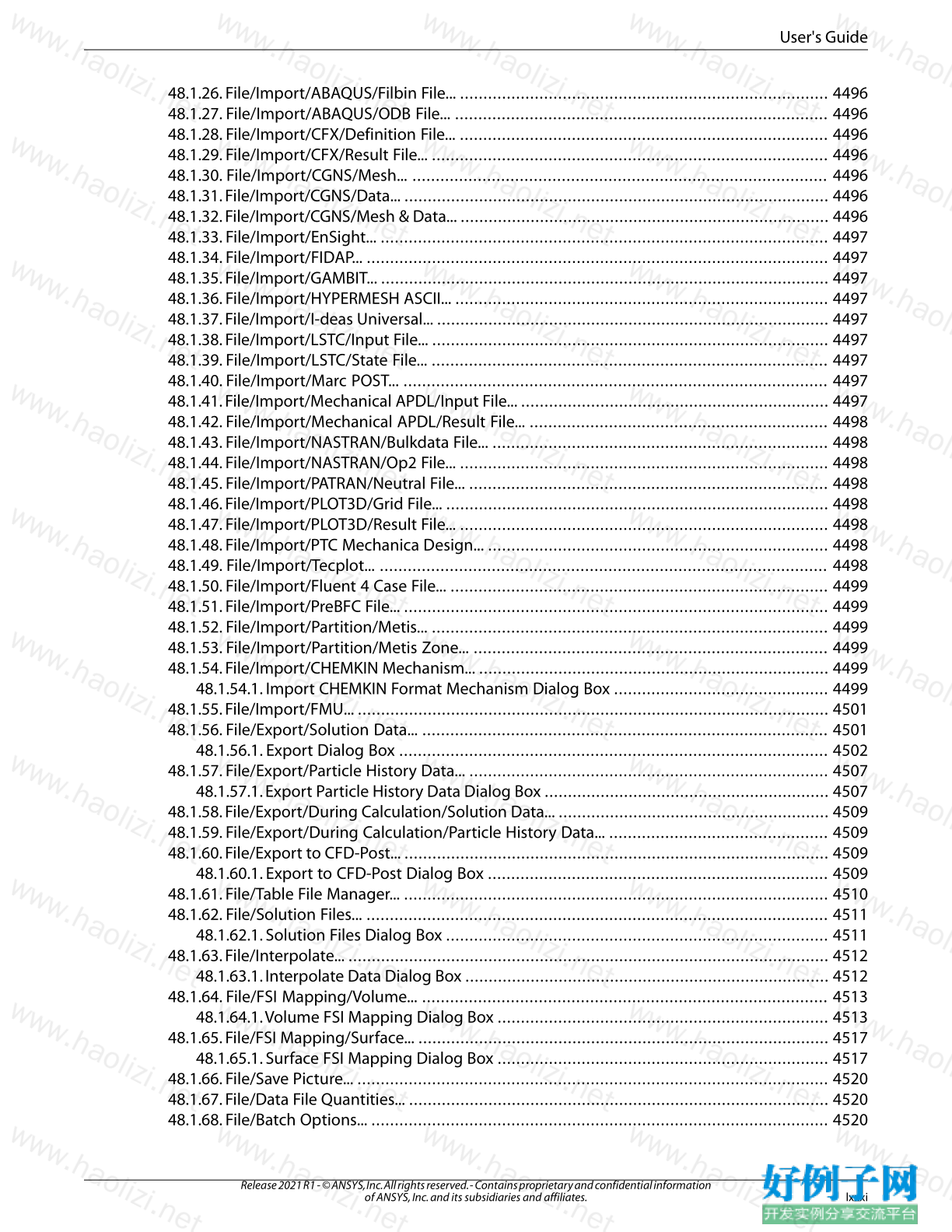
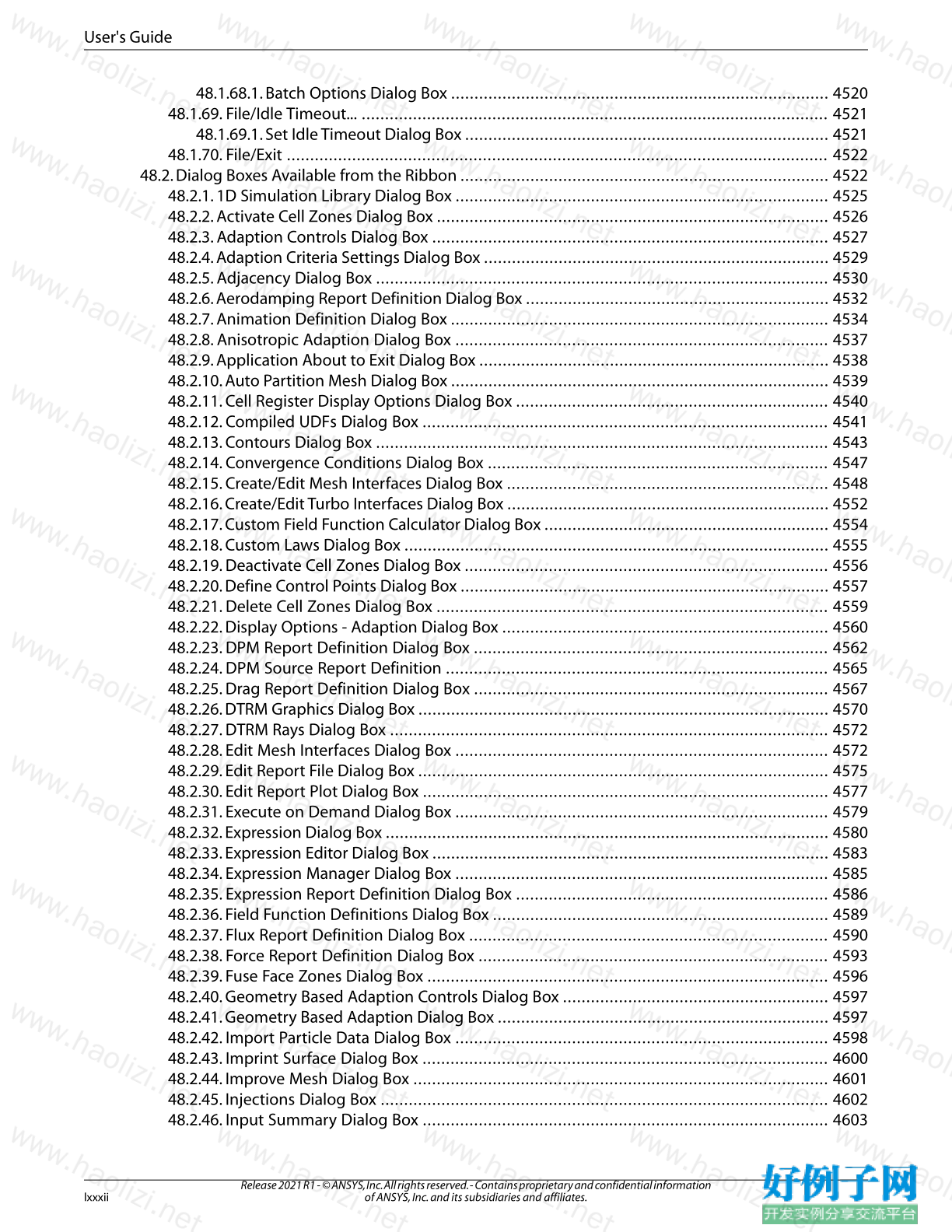
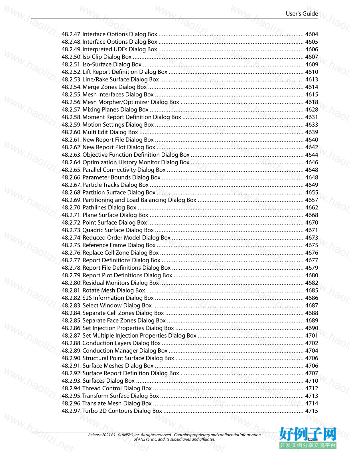
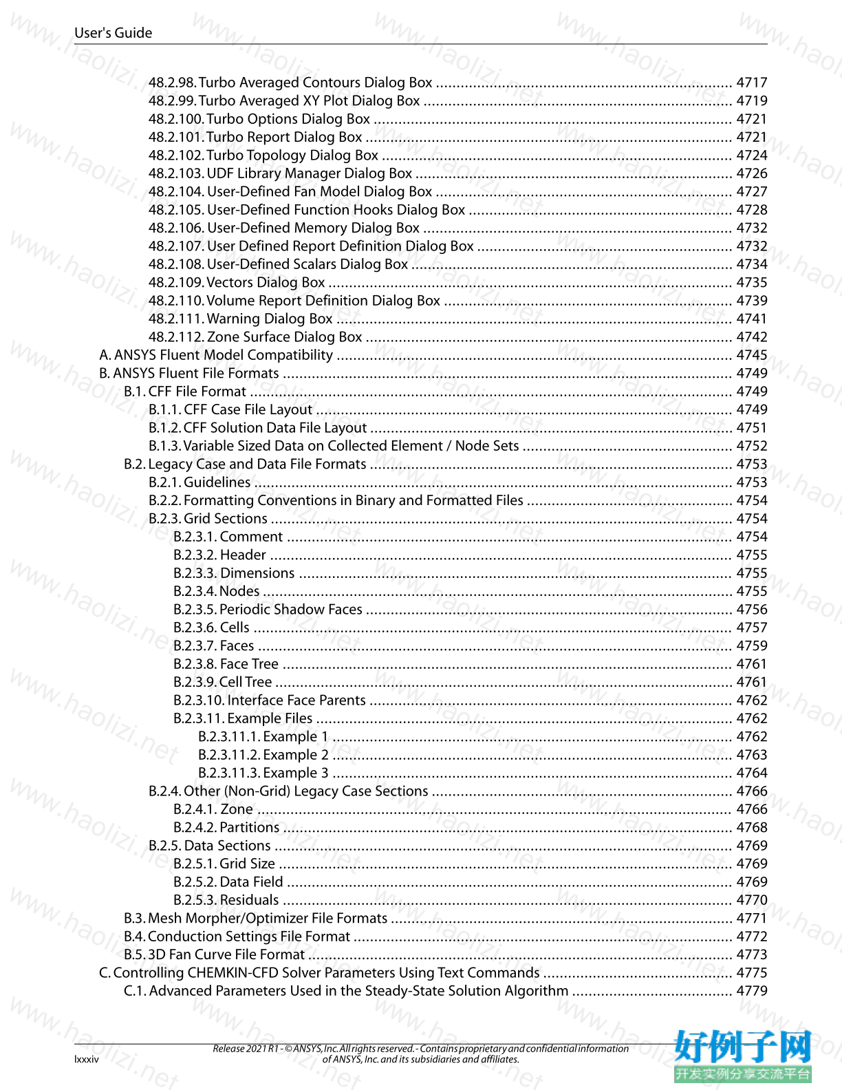

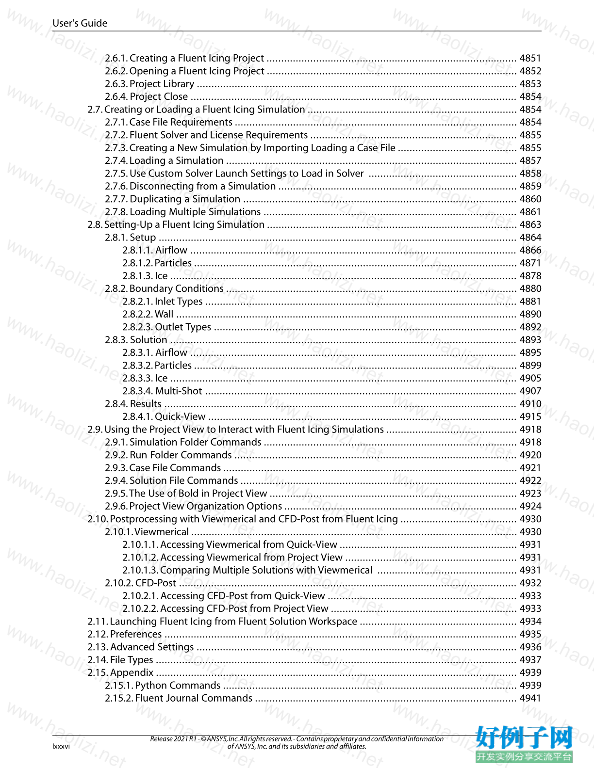
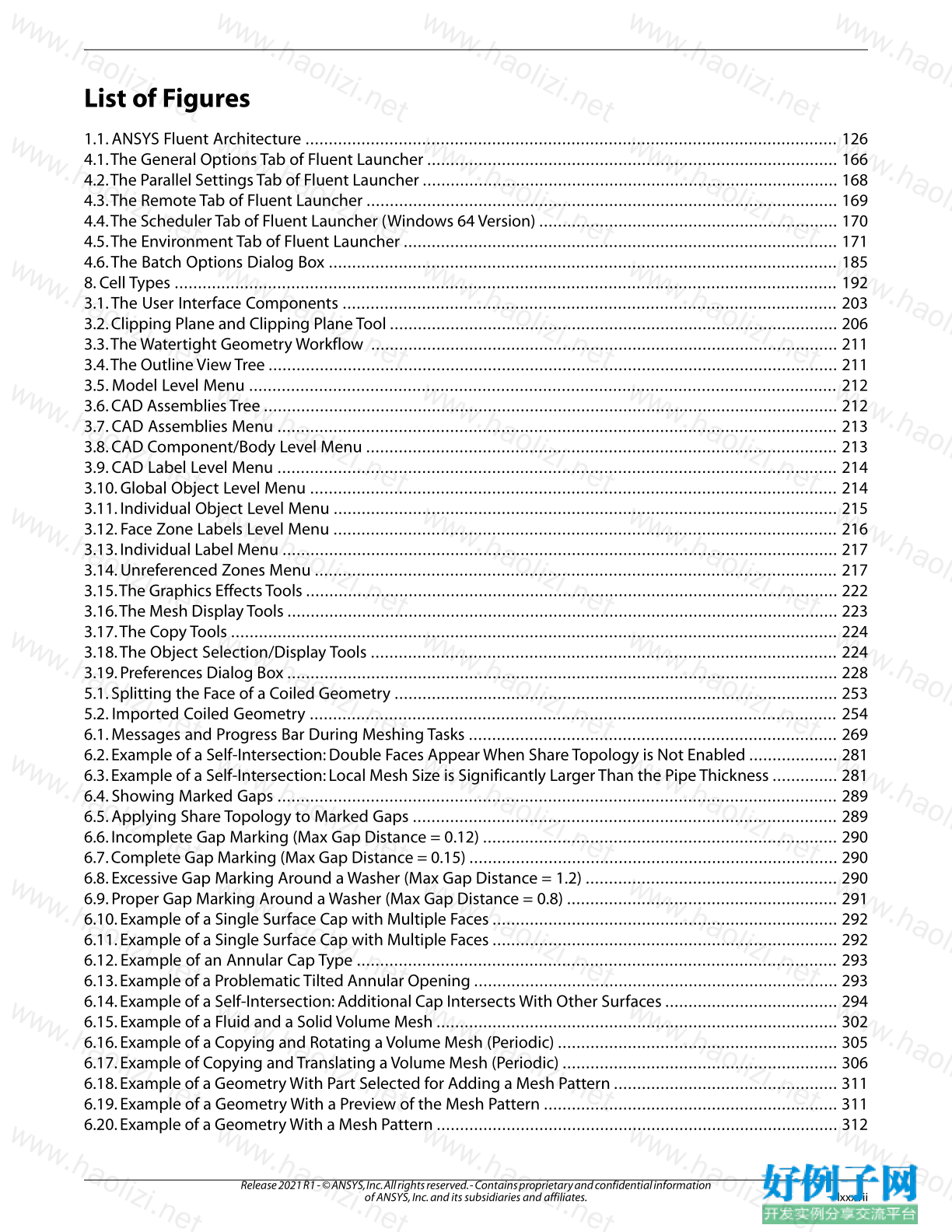
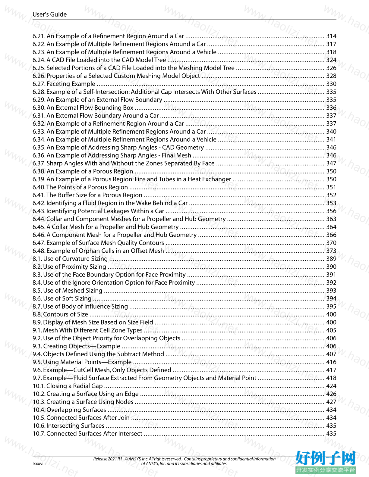
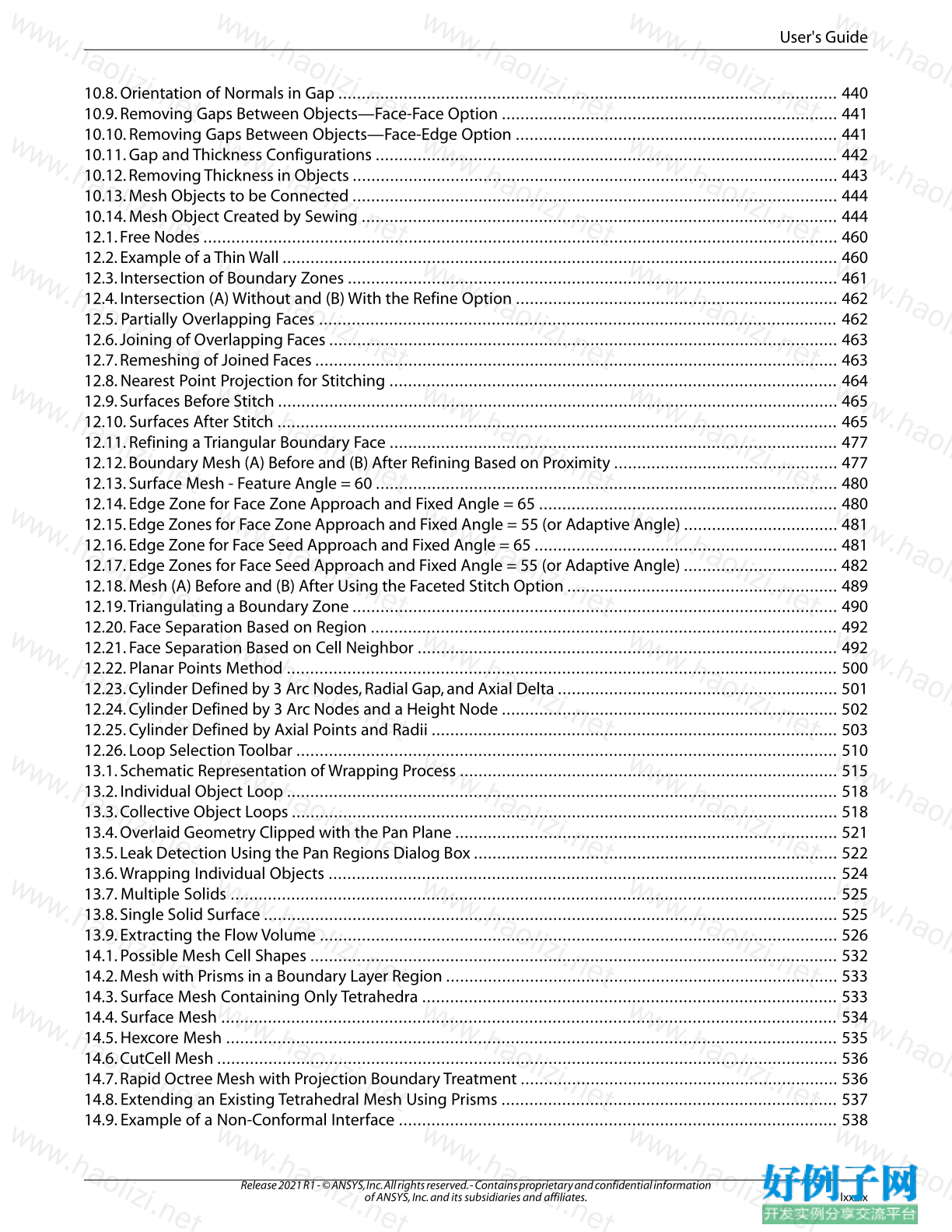
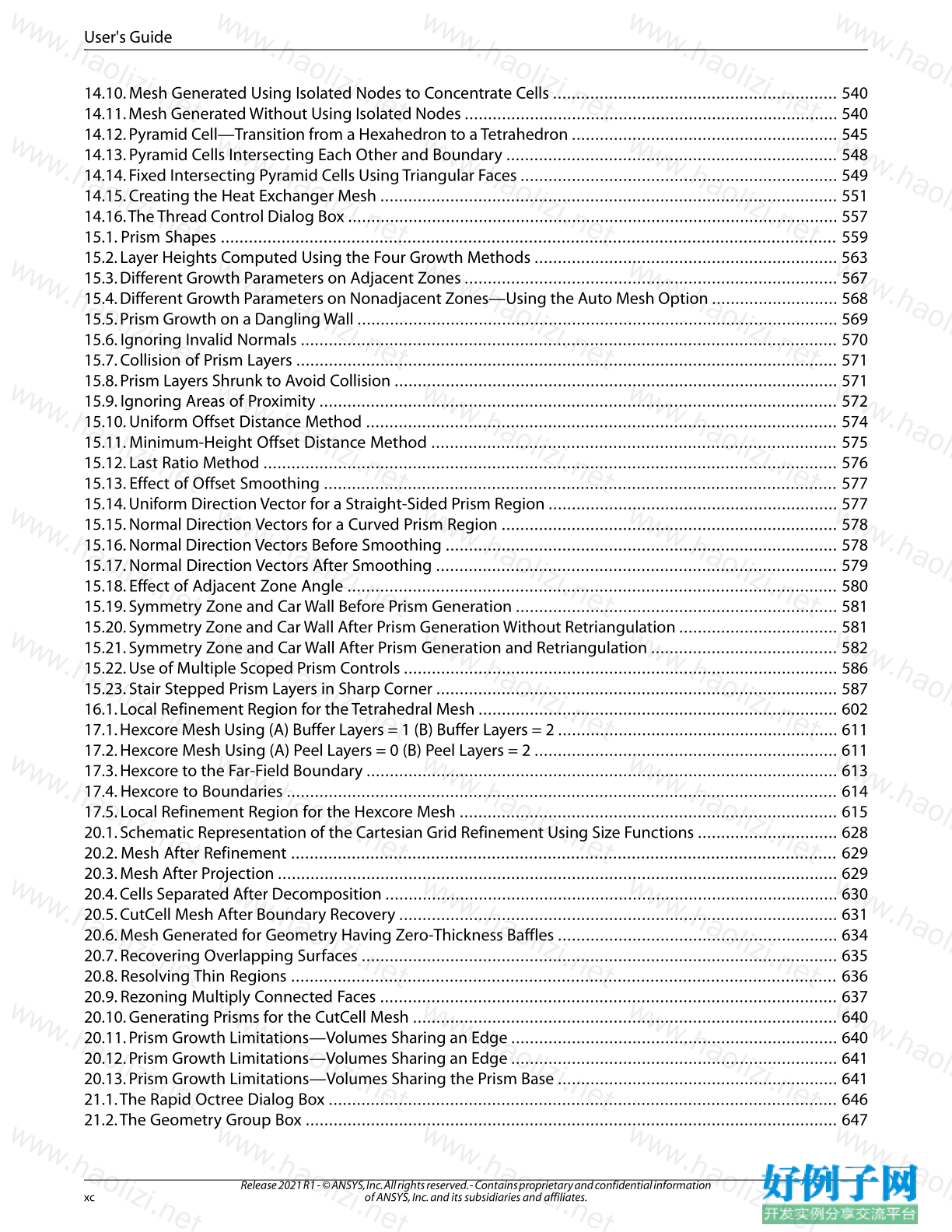
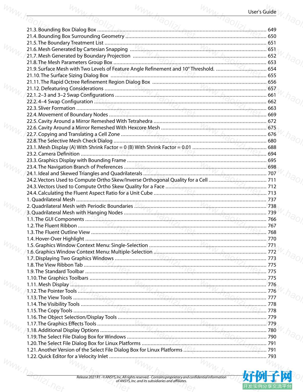
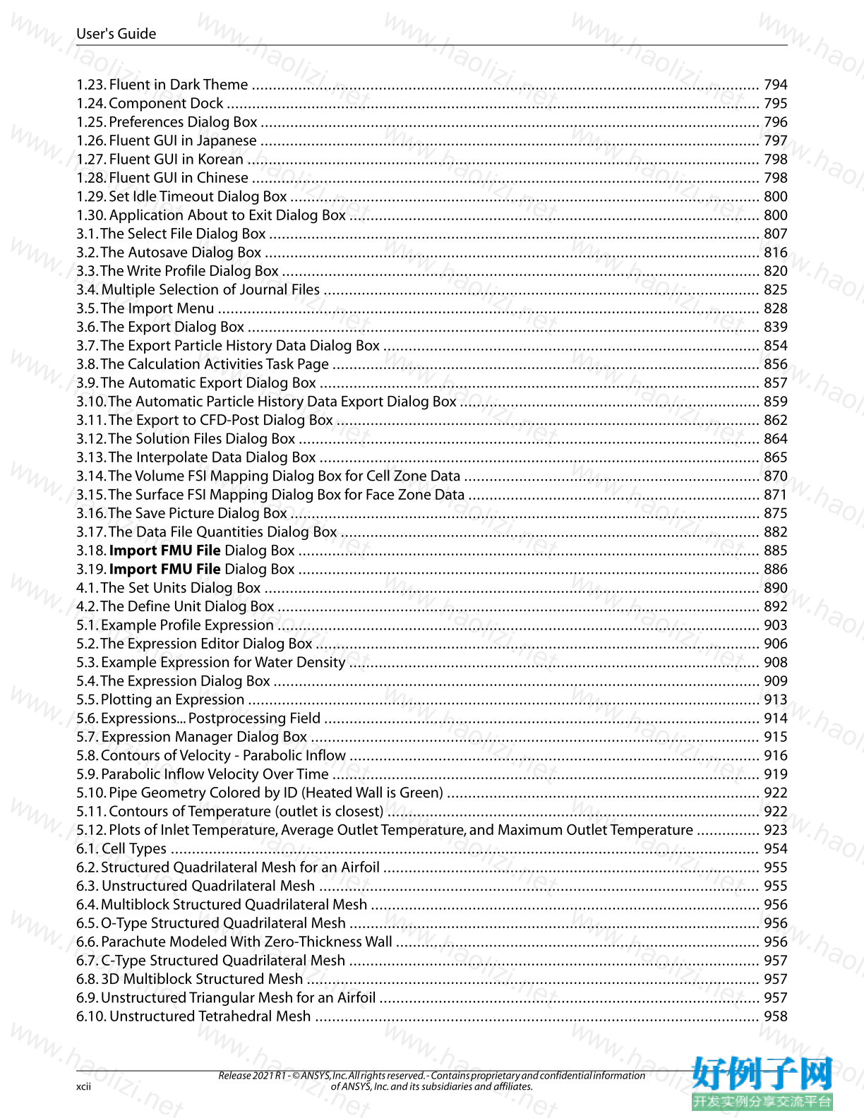
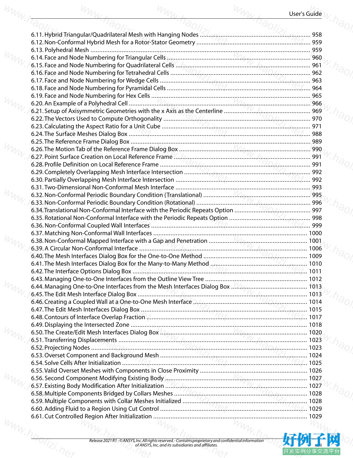

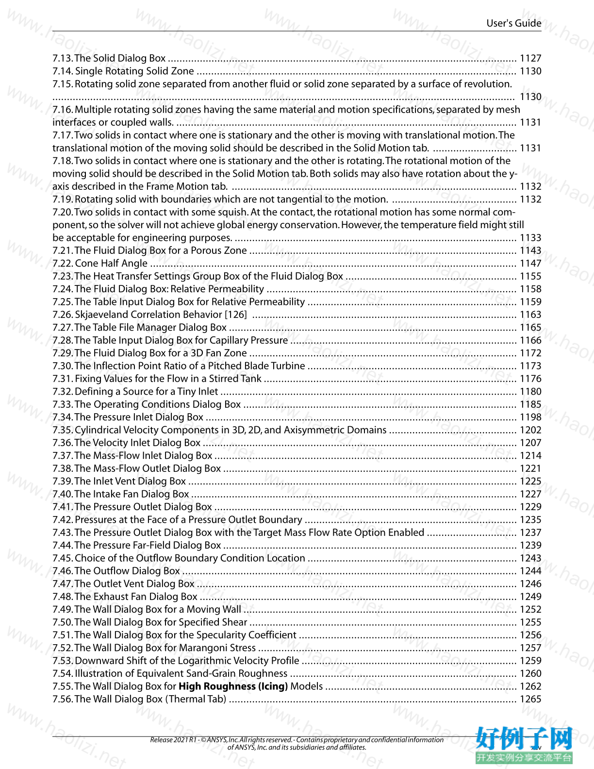
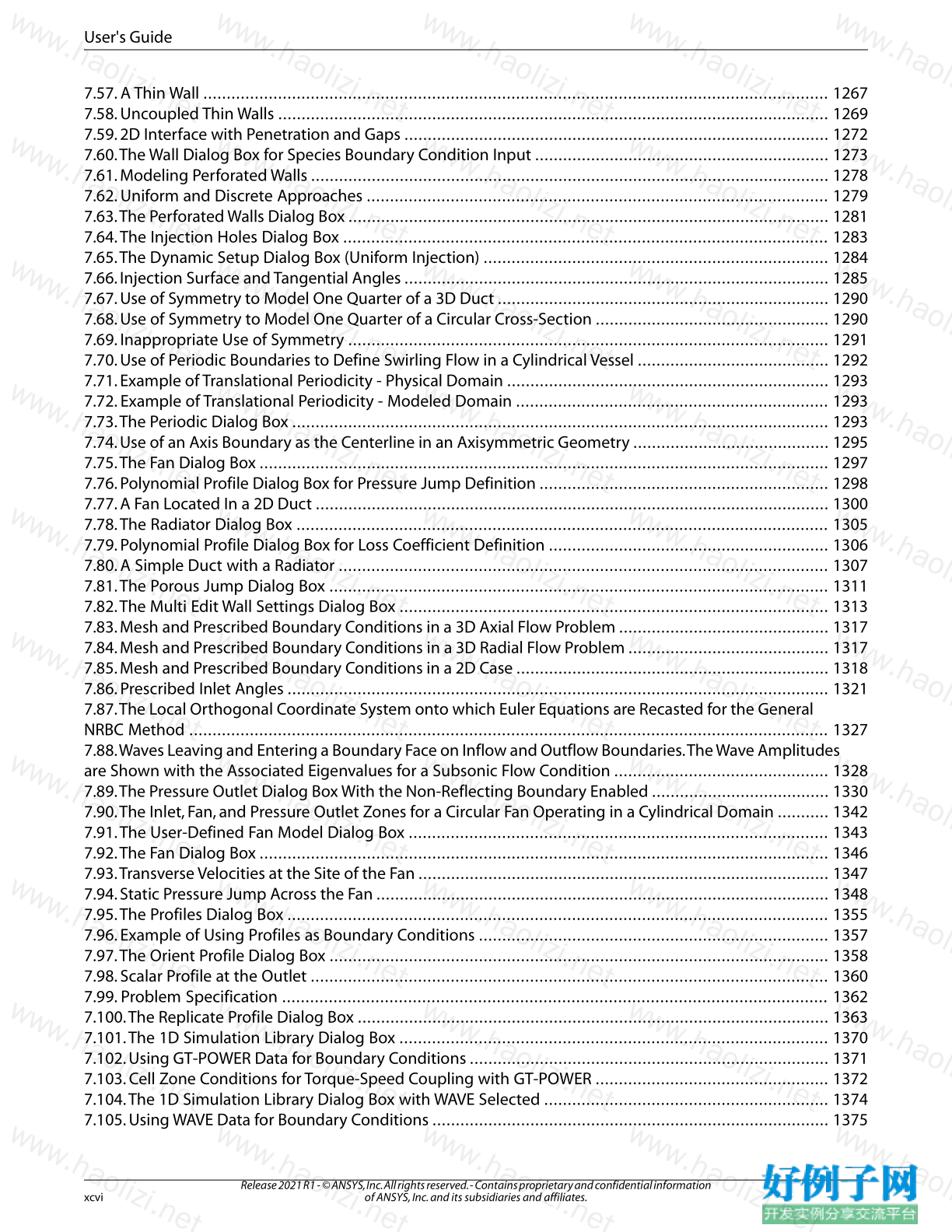
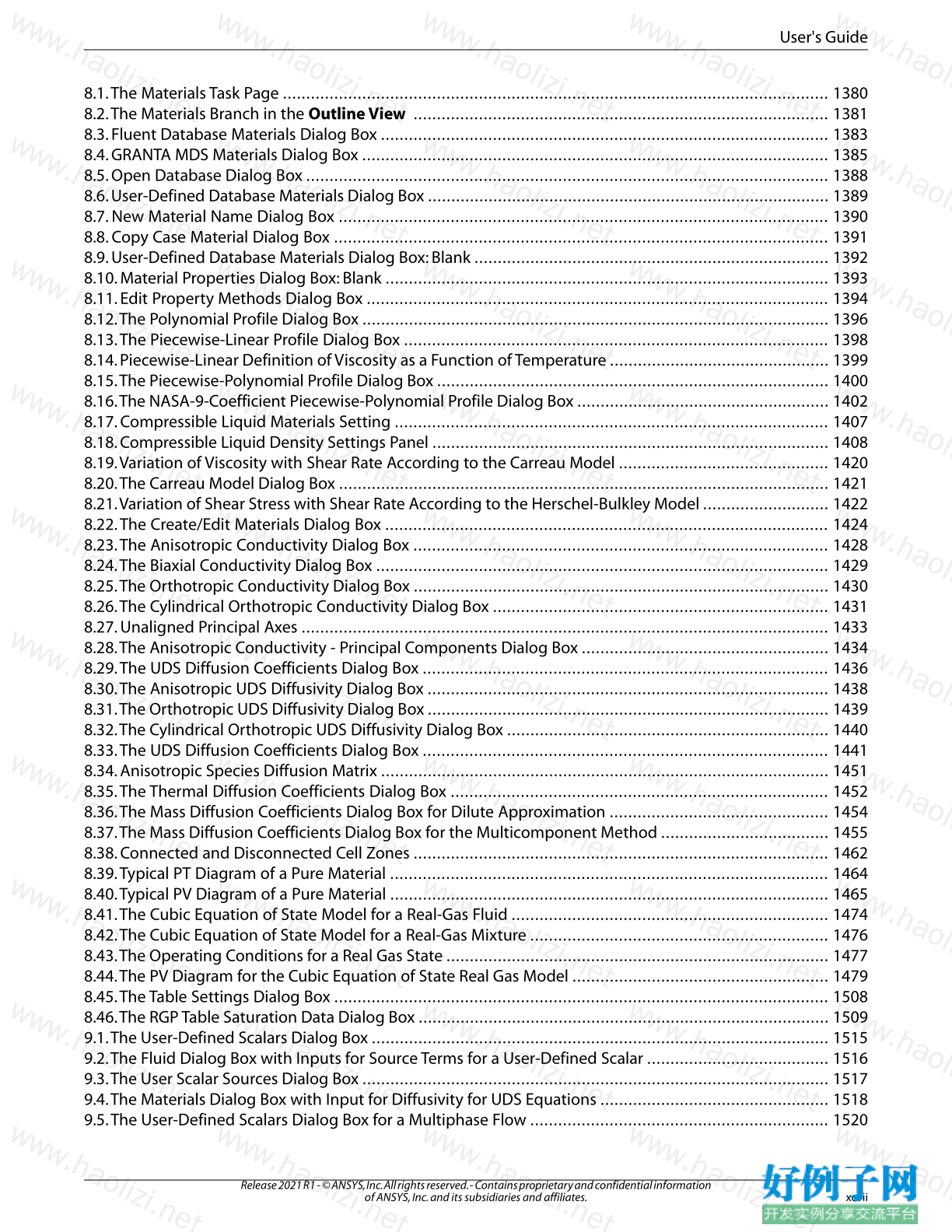
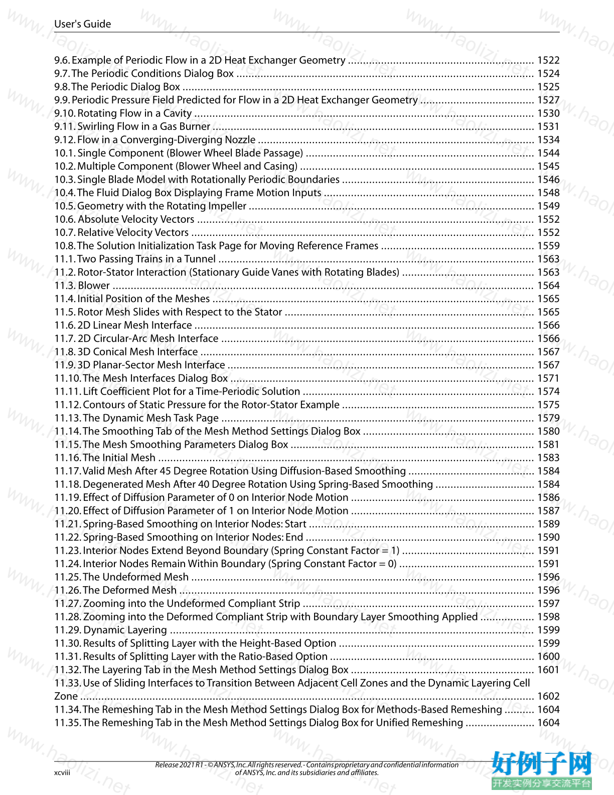

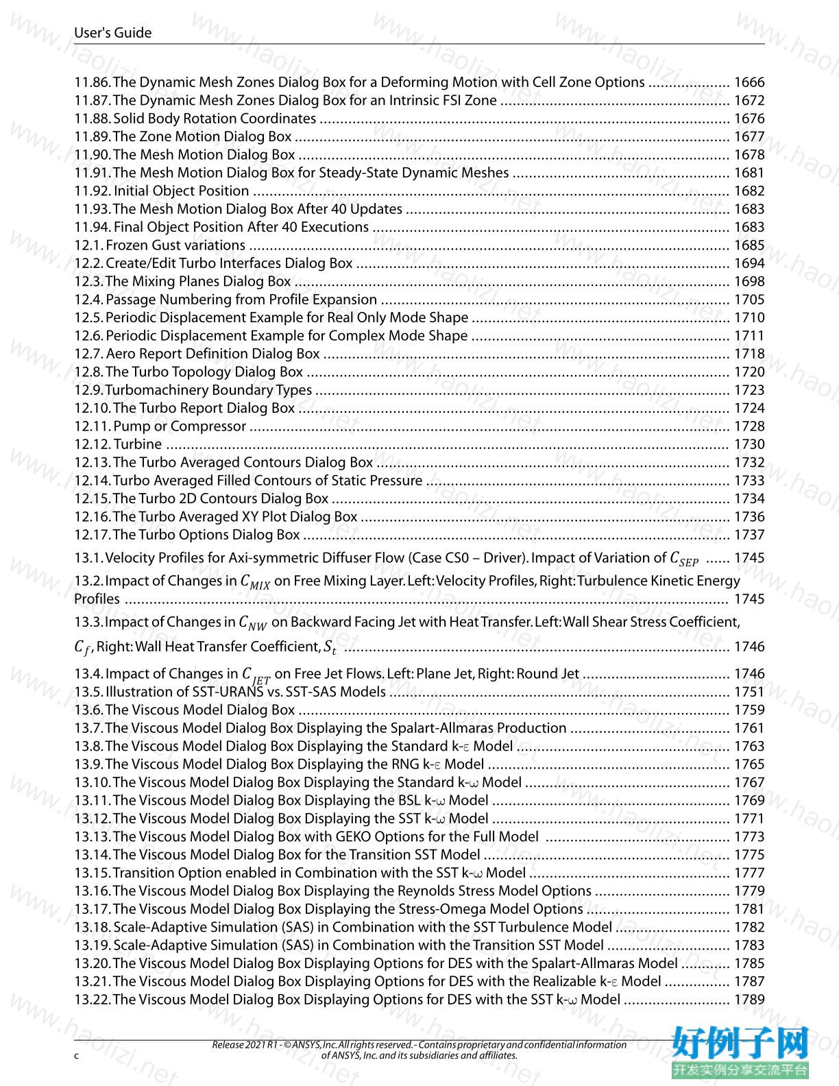
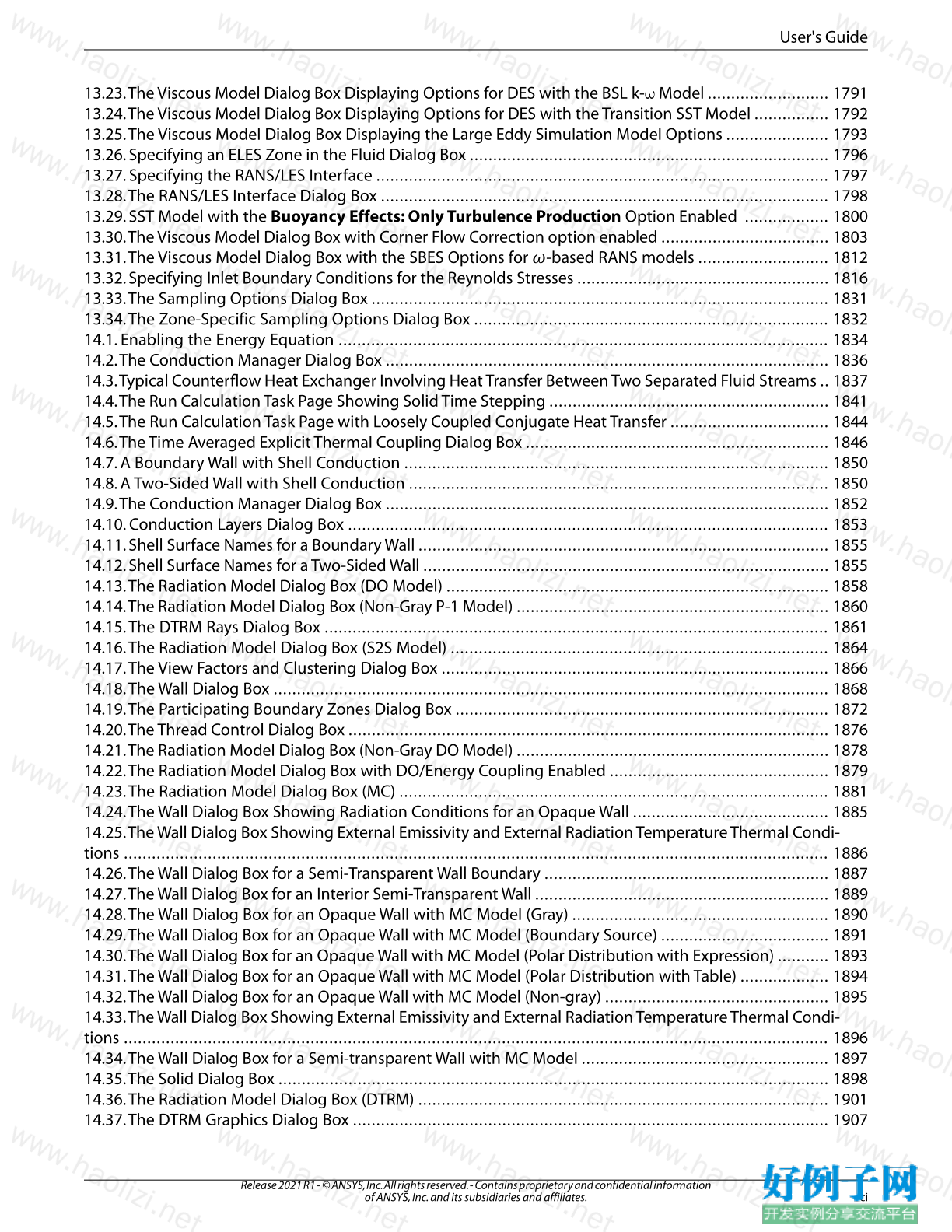
【核心代码】
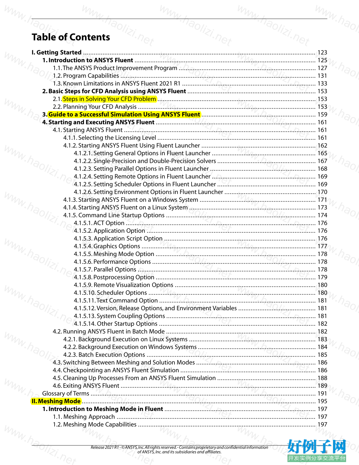
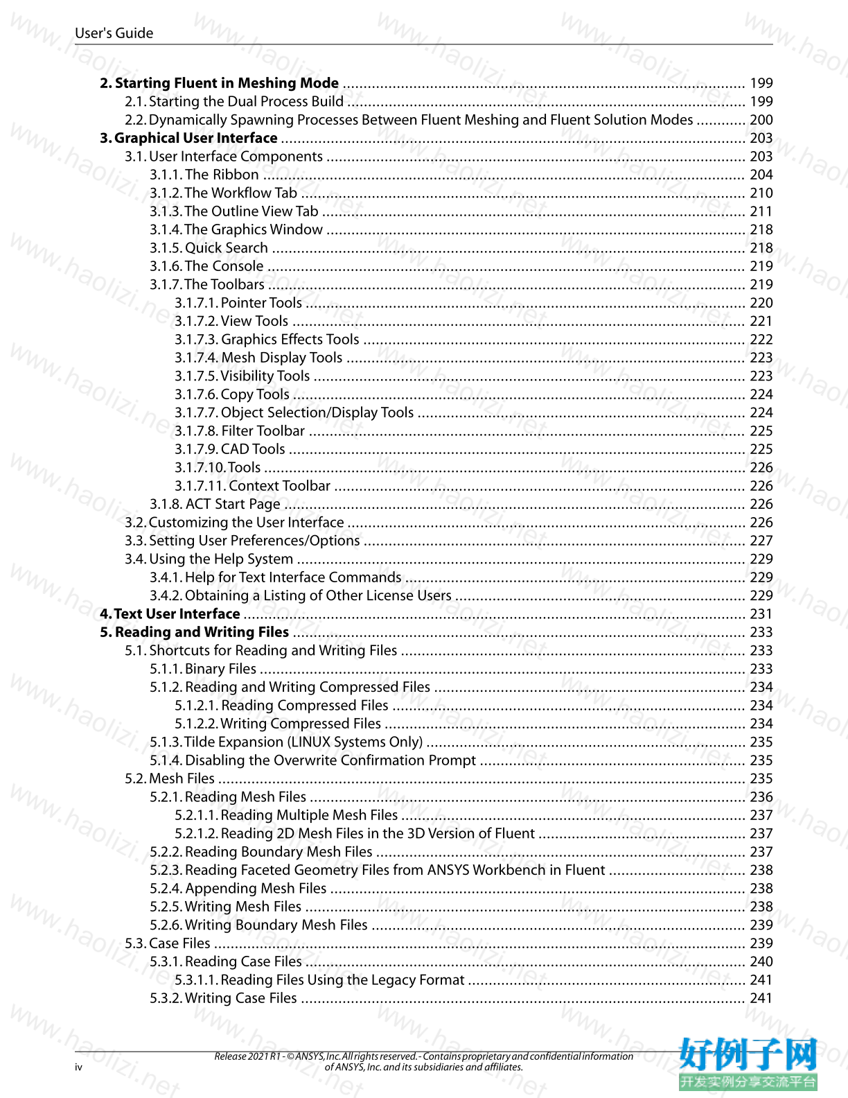
Table of Contents
I. Getting Started .................................................................................................................................... 123
1. Introduction to ANSYS Fluent ....................................................................................................... 125
1.1.The ANSYS Product Improvement Program .............................................................................. 127
1.2. Program Capabilities ............................................................................................................... 131
1.3. Known Limitations in ANSYS Fluent 2021 R1 ............................................................................ 133
2. Basic Steps for CFD Analysis using ANSYS Fluent ......................................................................... 153
2.1. Steps in Solving Your CFD Problem .......................................................................................... 153
2.2. Planning Your CFD Analysis ..................................................................................................... 153
3. Guide to a Successful Simulation Using ANSYS Fluent ................................................................. 159
4. Starting and Executing ANSYS Fluent ........................................................................................... 161
4.1. Starting ANSYS Fluent ............................................................................................................. 161
4.1.1. Selecting the Licensing Level .......................................................................................... 161
4.1.2. Starting ANSYS Fluent Using Fluent Launcher ................................................................. 162
4.1.2.1. Setting General Options in Fluent Launcher ........................................................... 165
4.1.2.2. Single-Precision and Double-Precision Solvers ........................................................ 167
4.1.2.3. Setting Parallel Options in Fluent Launcher ............................................................ 168
4.1.2.4. Setting Remote Options in Fluent Launcher ........................................................... 169
4.1.2.5. Setting Scheduler Options in Fluent Launcher ........................................................ 169
4.1.2.6. Setting Environment Options in Fluent Launcher .................................................... 170
4.1.3. Starting ANSYS Fluent on a Windows System .................................................................. 171
4.1.4. Starting ANSYS Fluent on a Linux System ........................................................................ 173
4.1.5. Command Line Startup Options ..................................................................................... 174
4.1.5.1. ACT Option ............................................................................................................ 176
4.1.5.2. Application Option ................................................................................................ 176
4.1.5.3. Application Script Option ...................................................................................... 176
4.1.5.4. Graphics Options ................................................................................................... 177
4.1.5.5. Meshing Mode Option ........................................................................................... 178
4.1.5.6. Performance Options ............................................................................................. 178
4.1.5.7. Parallel Options ..................................................................................................... 178
4.1.5.8. Postprocessing Option ........................................................................................... 179
4.1.5.9. Remote Visualization Options ................................................................................ 180
4.1.5.10. Scheduler Options ............................................................................................... 180
4.1.5.11.Text Command Option ......................................................................................... 181
4.1.5.12.Version, Release Options, and Environment Variables ............................................ 181
4.1.5.13. System Coupling Options ..................................................................................... 181
4.1.5.14. Other Startup Options ......................................................................................... 182
4.2. Running ANSYS Fluent in Batch Mode ..................................................................................... 182
4.2.1. Background Execution on Linux Systems ........................................................................ 183
4.2.2. Background Execution on Windows Systems ................................................................... 184
4.2.3. Batch Execution Options ................................................................................................ 185
4.3. Switching Between Meshing and Solution Modes .................................................................... 186
4.4. Checkpointing an ANSYS Fluent Simulation ............................................................................. 186
4.5. Cleaning Up Processes From an ANSYS Fluent Simulation ........................................................ 188
4.6. Exiting ANSYS Fluent ............................................................................................................... 189
Glossary of Terms ................................................................................................................................ 191
II. Meshing Mode ..................................................................................................................................... 195
1. Introduction to Meshing Mode in Fluent ...................................................................................... 197
1.1. Meshing Approach ................................................................................................................. 197
1.2. Meshing Mode Capabilities ..................................................................................................... 197
iii
Release 2021 R1 - © ANSYS, Inc. All rights reserved. - Contains proprietary and confidential information
of ANSYS, Inc. and its subsidiaries and affiliates.
2. Starting Fluent in Meshing Mode ................................................................................................. 199
2.1. Starting the Dual Process Build ................................................................................................ 199
2.2. Dynamically Spawning Processes Between Fluent Meshing and Fluent Solution Modes ............ 200
3. Graphical User Interface ................................................................................................................ 203
3.1. User Interface Components ..................................................................................................... 203
3.1.1.The Ribbon .................................................................................................................... 204
3.1.2.The Workflow Tab ........................................................................................................... 210
3.1.3.The Outline View Tab ...................................................................................................... 211
3.1.4.The Graphics Window ..................................................................................................... 218
3.1.5. Quick Search .................................................................................................................. 218
3.1.6.The Console ................................................................................................................... 219
3.1.7.The Toolbars ................................................................................................................... 219
3.1.7.1. Pointer Tools .......................................................................................................... 220
3.1.7.2.View Tools ............................................................................................................. 221
3.1.7.3. Graphics Effects Tools ............................................................................................ 222
3.1.7.4. Mesh Display Tools ................................................................................................ 223
3.1.7.5.Visibility Tools ........................................................................................................ 223
3.1.7.6. Copy Tools ............................................................................................................. 224
3.1.7.7. Object Selection/Display Tools ............................................................................... 224
3.1.7.8. Filter Toolbar ......................................................................................................... 225
3.1.7.9. CAD Tools .............................................................................................................. 225
3.1.7.10.Tools .................................................................................................................... 226
3.1.7.11. Context Toolbar ................................................................................................... 226
3.1.8. ACT Start Page ............................................................................................................... 226
3.2. Customizing the User Interface ................................................................................................ 226
3.3. Setting User Preferences/Options ............................................................................................ 227
3.4. Using the Help System ............................................................................................................ 229
3.4.1. Help for Text Interface Commands .................................................................................. 229
3.4.2. Obtaining a Listing of Other License Users ...................................................................... 229
4.Text User Interface ......................................................................................................................... 231
5. Reading and Writing Files ............................................................................................................. 233
5.1. Shortcuts for Reading and Writing Files ................................................................................... 233
5.1.1. Binary Files ..................................................................................................................... 233
5.1.2. Reading and Writing Compressed Files ........................................................................... 234
5.1.2.1. Reading Compressed Files ..................................................................................... 234
5.1.2.2.Writing Compressed Files ....................................................................................... 234
5.1.3.Tilde Expansion (LINUX Systems Only) ............................................................................. 235
5.1.4. Disabling the Overwrite Confirmation Prompt ................................................................ 235
5.2. Mesh Files ............................................................................................................................... 235
5.2.1. Reading Mesh Files ......................................................................................................... 236
5.2.1.1. Reading Multiple Mesh Files ................................................................................... 237
5.2.1.2. Reading 2D Mesh Files in the 3D Version of Fluent .................................................. 237
5.2.2. Reading Boundary Mesh Files ......................................................................................... 237
5.2.3. Reading Faceted Geometry Files from ANSYS Workbench in Fluent ................................. 238
5.2.4. Appending Mesh Files .................................................................................................... 238
5.2.5.Writing Mesh Files .......................................................................................................... 238
5.2.6.Writing Boundary Mesh Files .......................................................................................... 239
5.3. Case Files ................................................................................................................................ 239
5.3.1. Reading Case Files .......................................................................................................... 240
5.3.1.1. Reading Files Using the Legacy Format ................................................................... 241
5.3.2.Writing Case Files ........................................................................................................... 241
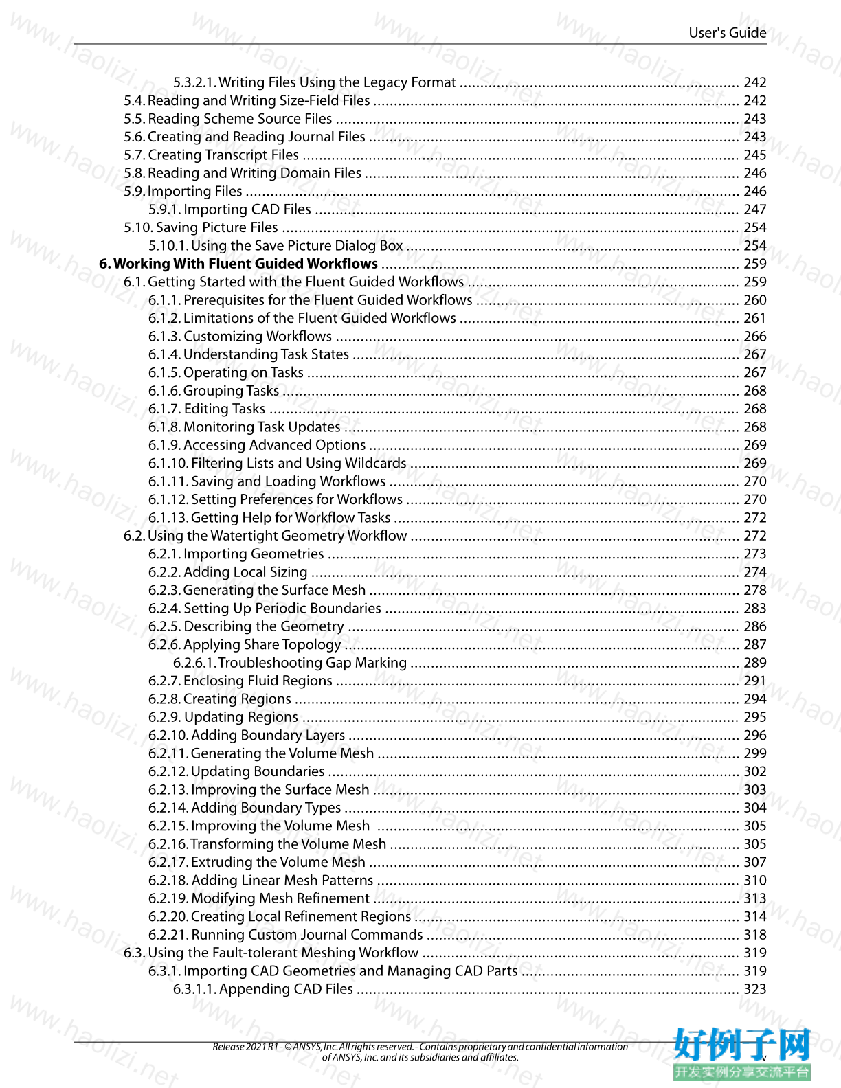
Release 2021 R1 - © ANSYS, Inc. All rights reserved. - Contains proprietary and confidential information
of ANSYS, Inc. and its subsidiaries and affiliates. iv
User's Guide
5.3.2.1.Writing Files Using the Legacy Format .................................................................... 242
5.4. Reading and Writing Size-Field Files ......................................................................................... 242
5.5. Reading Scheme Source Files .................................................................................................. 243
5.6. Creating and Reading Journal Files .......................................................................................... 243
5.7. Creating Transcript Files .......................................................................................................... 245
5.8. Reading and Writing Domain Files ........................................................................................... 246
5.9. Importing Files ........................................................................................................................ 246
5.9.1. Importing CAD Files ....................................................................................................... 247
5.10. Saving Picture Files ............................................................................................................... 254
5.10.1. Using the Save Picture Dialog Box ................................................................................. 254
6.Working With Fluent Guided Workflows ....................................................................................... 259
6.1. Getting Started with the Fluent Guided Workflows .................................................................. 259
6.1.1. Prerequisites for the Fluent Guided Workflows ................................................................ 260
6.1.2. Limitations of the Fluent Guided Workflows .................................................................... 261
6.1.3. Customizing Workflows .................................................................................................. 266
6.1.4. Understanding Task States .............................................................................................. 267
6.1.5. Operating on Tasks ......................................................................................................... 267
6.1.6. Grouping Tasks ............................................................................................................... 268
6.1.7. Editing Tasks .................................................................................................................. 268
6.1.8. Monitoring Task Updates ................................................................................................ 268
6.1.9. Accessing Advanced Options .......................................................................................... 269
6.1.10. Filtering Lists and Using Wildcards ................................................................................ 269
6.1.11. Saving and Loading Workflows ..................................................................................... 270
6.1.12. Setting Preferences for Workflows ................................................................................. 270
6.1.13. Getting Help for Workflow Tasks .................................................................................... 272
6.2. Using the Watertight Geometry Workflow ................................................................................ 272
6.2.1. Importing Geometries .................................................................................................... 273
6.2.2. Adding Local Sizing ........................................................................................................ 274
6.2.3. Generating the Surface Mesh .......................................................................................... 278
6.2.4. Setting Up Periodic Boundaries ...................................................................................... 283
6.2.5. Describing the Geometry ............................................................................................... 286
6.2.6. Applying Share Topology ................................................................................................ 287
6.2.6.1.Troubleshooting Gap Marking ................................................................................ 289
6.2.7. Enclosing Fluid Regions .................................................................................................. 291
6.2.8. Creating Regions ............................................................................................................ 294
6.2.9. Updating Regions .......................................................................................................... 295
6.2.10. Adding Boundary Layers ............................................................................................... 296
6.2.11. Generating the Volume Mesh ........................................................................................ 299
6.2.12. Updating Boundaries .................................................................................................... 302
6.2.13. Improving the Surface Mesh ......................................................................................... 303
6.2.14. Adding Boundary Types ................................................................................................ 304
6.2.15. Improving the Volume Mesh ........................................................................................ 305
6.2.16.Transforming the Volume Mesh ..................................................................................... 305
6.2.17. Extruding the Volume Mesh .......................................................................................... 307
6.2.18. Adding Linear Mesh Patterns ........................................................................................ 310
6.2.19. Modifying Mesh Refinement ......................................................................................... 313
6.2.20. Creating Local Refinement Regions ............................................................................... 314
6.2.21. Running Custom Journal Commands ............................................................................ 318
6.3. Using the Fault-tolerant Meshing Workflow ............................................................................. 319
6.3.1. Importing CAD Geometries and Managing CAD Parts ..................................................... 319
6.3.1.1. Appending CAD Files ............................................................................................. 323
v
Release 2021 R1 - © ANSYS, Inc. All rights reserved. - Contains proprietary and confidential information
of ANSYS, Inc. and its subsidiaries and affiliates.
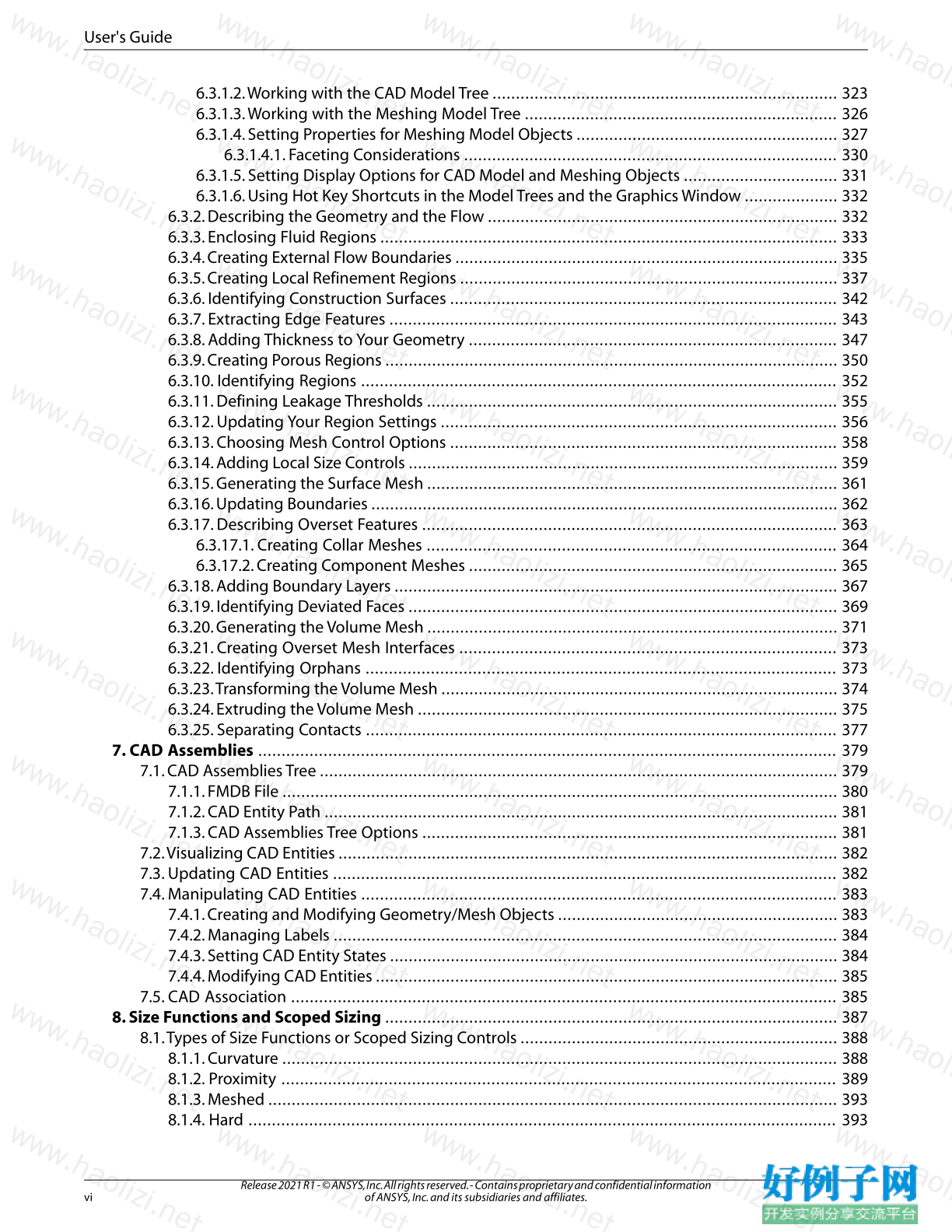
User's Guide
6.3.1.2.Working with the CAD Model Tree .......................................................................... 323
6.3.1.3.Working with the Meshing Model Tree ................................................................... 326
6.3.1.4. Setting Properties for Meshing Model Objects ........................................................ 327
6.3.1.4.1. Faceting Considerations ................................................................................ 330
6.3.1.5. Setting Display Options for CAD Model and Meshing Objects ................................. 331
6.3.1.6. Using Hot Key Shortcuts in the Model Trees and the Graphics Window .................... 332
6.3.2. Describing the Geometry and the Flow ........................................................................... 332
6.3.3. Enclosing Fluid Regions .................................................................................................. 333
6.3.4. Creating External Flow Boundaries .................................................................................. 335
6.3.5. Creating Local Refinement Regions ................................................................................. 337
6.3.6. Identifying Construction Surfaces ................................................................................... 342
6.3.7. Extracting Edge Features ................................................................................................ 343
6.3.8. Adding Thickness to Your Geometry ............................................................................... 347
6.3.9. Creating Porous Regions ................................................................................................. 350
6.3.10. Identifying Regions ...................................................................................................... 352
6.3.11. Defining Leakage Thresholds ........................................................................................ 355
6.3.12. Updating Your Region Settings ..................................................................................... 356
6.3.13. Choosing Mesh Control Options ................................................................................... 358
6.3.14. Adding Local Size Controls ............................................................................................ 359
6.3.15. Generating the Surface Mesh ........................................................................................ 361
6.3.16. Updating Boundaries .................................................................................................... 362
6.3.17. Describing Overset Features ......................................................................................... 363
6.3.17.1. Creating Collar Meshes ........................................................................................ 364
6.3.17.2. Creating Component Meshes ............................................................................... 365
6.3.18. Adding Boundary Layers ............................................................................................... 367
6.3.19. Identifying Deviated Faces ............................................................................................ 369
6.3.20. Generating the Volume Mesh ........................................................................................ 371
6.3.21. Creating Overset Mesh Interfaces ................................................................................. 373
6.3.22. Identifying Orphans ..................................................................................................... 373
6.3.23.Transforming the Volume Mesh ..................................................................................... 374
6.3.24. Extruding the Volume Mesh .......................................................................................... 375
6.3.25. Separating Contacts ..................................................................................................... 377
7. CAD Assemblies ............................................................................................................................ 379
7.1. CAD Assemblies Tree ............................................................................................................... 379
7.1.1. FMDB File ....................................................................................................................... 380
7.1.2. CAD Entity Path .............................................................................................................. 381
7.1.3. CAD Assemblies Tree Options ......................................................................................... 381
7.2.Visualizing CAD Entities ........................................................................................................... 382
7.3. Updating CAD Entities ............................................................................................................ 382
7.4. Manipulating CAD Entities ...................................................................................................... 383
7.4.1. Creating and Modifying Geometry/Mesh Objects ............................................................ 383
7.4.2. Managing Labels ............................................................................................................ 384
7.4.3. Setting CAD Entity States ................................................................................................ 384
7.4.4. Modifying CAD Entities ................................................................................................... 385
7.5. CAD Association ..................................................................................................................... 385
8. Size Functions and Scoped Sizing ................................................................................................. 387
8.1.Types of Size Functions or Scoped Sizing Controls .................................................................... 388
8.1.1. Curvature ....................................................................................................................... 388
8.1.2. Proximity ....................................................................................................................... 389
8.1.3. Meshed .......................................................................................................................... 393
8.1.4. Hard .............................................................................................................................. 393
Release 2021 R1 - © ANSYS, Inc. All rights reserved. - Contains proprietary and confidential information
of ANSYS, Inc. and its subsidiaries and affiliates. vi
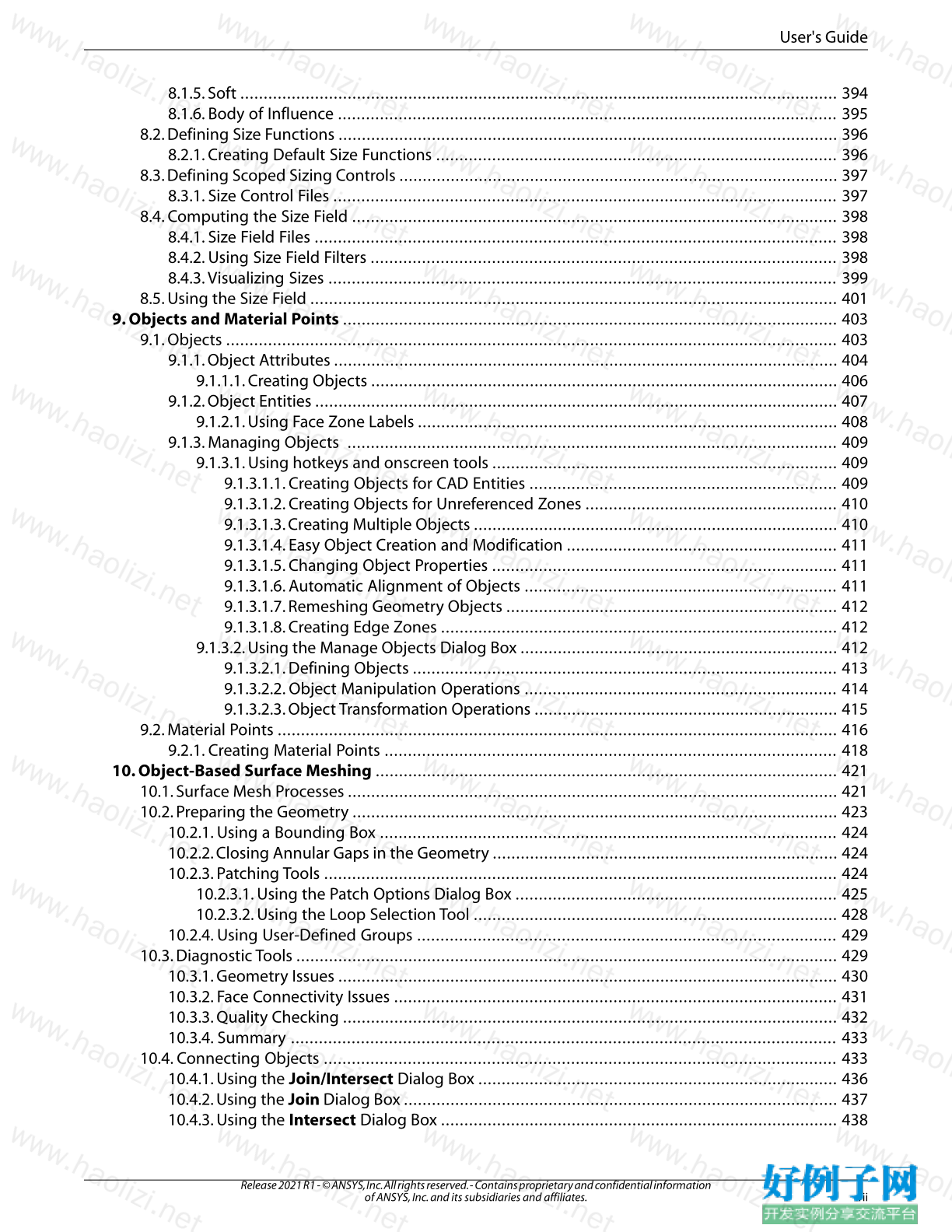
User's Guide
8.1.5. Soft ................................................................................................................................ 394
8.1.6. Body of Influence ........................................................................................................... 395
8.2. Defining Size Functions ........................................................................................................... 396
8.2.1. Creating Default Size Functions ...................................................................................... 396
8.3. Defining Scoped Sizing Controls .............................................................................................. 397
8.3.1. Size Control Files ............................................................................................................ 397
8.4. Computing the Size Field ........................................................................................................ 398
8.4.1. Size Field Files ................................................................................................................ 398
8.4.2. Using Size Field Filters .................................................................................................... 398
8.4.3.Visualizing Sizes ............................................................................................................. 399
8.5. Using the Size Field ................................................................................................................. 401
9. Objects and Material Points .......................................................................................................... 403
9.1. Objects ................................................................................................................................... 403
9.1.1. Object Attributes ............................................................................................................ 404
9.1.1.1. Creating Objects .................................................................................................... 406
9.1.2. Object Entities ................................................................................................................ 407
9.1.2.1. Using Face Zone Labels .......................................................................................... 408
9.1.3. Managing Objects ......................................................................................................... 409
9.1.3.1. Using hotkeys and onscreen tools .......................................................................... 409
9.1.3.1.1. Creating Objects for CAD Entities .................................................................. 409
9.1.3.1.2. Creating Objects for Unreferenced Zones ...................................................... 410
9.1.3.1.3. Creating Multiple Objects .............................................................................. 410
9.1.3.1.4. Easy Object Creation and Modification .......................................................... 411
9.1.3.1.5. Changing Object Properties .......................................................................... 411
9.1.3.1.6. Automatic Alignment of Objects ................................................................... 411
9.1.3.1.7. Remeshing Geometry Objects ....................................................................... 412
9.1.3.1.8. Creating Edge Zones ..................................................................................... 412
9.1.3.2. Using the Manage Objects Dialog Box .................................................................... 412
9.1.3.2.1. Defining Objects ........................................................................................... 413
9.1.3.2.2. Object Manipulation Operations ................................................................... 414
9.1.3.2.3. Object Transformation Operations ................................................................. 415
9.2. Material Points ........................................................................................................................ 416
9.2.1. Creating Material Points ................................................................................................. 418
10. Object-Based Surface Meshing ................................................................................................... 421
10.1. Surface Mesh Processes ......................................................................................................... 421
10.2. Preparing the Geometry ........................................................................................................ 423
10.2.1. Using a Bounding Box .................................................................................................. 424
10.2.2. Closing Annular Gaps in the Geometry .......................................................................... 424
10.2.3. Patching Tools .............................................................................................................. 424
10.2.3.1. Using the Patch Options Dialog Box ..................................................................... 425
10.2.3.2. Using the Loop Selection Tool .............................................................................. 428
10.2.4. Using User-Defined Groups .......................................................................................... 429
10.3. Diagnostic Tools .................................................................................................................... 429
10.3.1. Geometry Issues ........................................................................................................... 430
10.3.2. Face Connectivity Issues ............................................................................................... 431
10.3.3. Quality Checking .......................................................................................................... 432
10.3.4. Summary ..................................................................................................................... 433
10.4. Connecting Objects .............................................................................................................. 433
10.4.1. Using the Join/Intersect Dialog Box ............................................................................. 436
10.4.2. Using the Join Dialog Box ............................................................................................. 437
10.4.3. Using the Intersect Dialog Box ..................................................................................... 438
vii
Release 2021 R1 - © ANSYS, Inc. All rights reserved. - Contains proprietary and confidential information
of ANSYS, Inc. and its subsidiaries and affiliates.
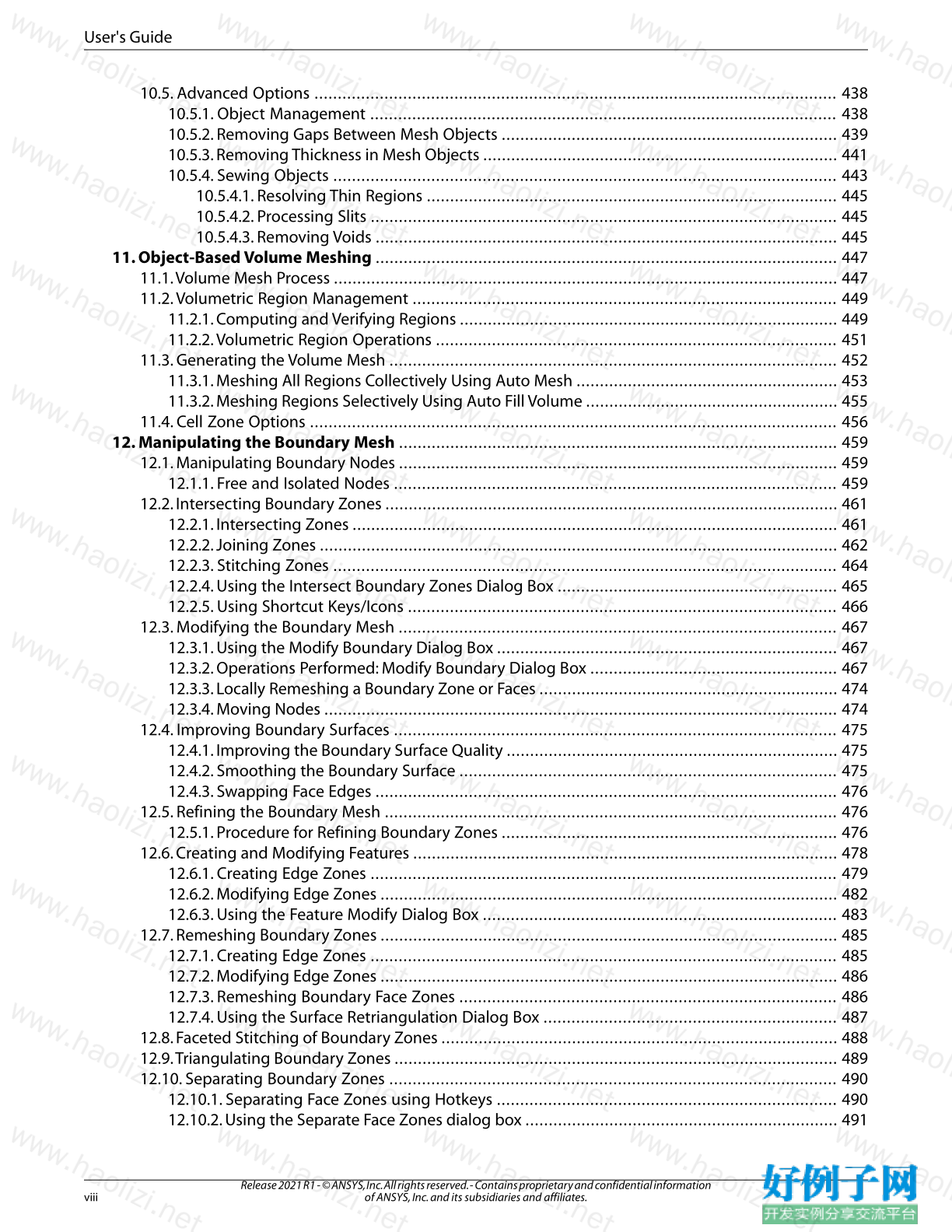
User's Guide
10.5. Advanced Options ................................................................................................................ 438
10.5.1. Object Management .................................................................................................... 438
10.5.2. Removing Gaps Between Mesh Objects ........................................................................ 439
10.5.3. Removing Thickness in Mesh Objects ............................................................................ 441
10.5.4. Sewing Objects ............................................................................................................ 443
10.5.4.1. Resolving Thin Regions ........................................................................................ 445
10.5.4.2. Processing Slits .................................................................................................... 445
10.5.4.3. Removing Voids ................................................................................................... 445
11. Object-Based Volume Meshing ................................................................................................... 447
11.1.Volume Mesh Process ............................................................................................................ 447
11.2.Volumetric Region Management ........................................................................................... 449
11.2.1. Computing and Verifying Regions ................................................................................. 449
11.2.2.Volumetric Region Operations ...................................................................................... 451
11.3. Generating the Volume Mesh ................................................................................................ 452
11.3.1. Meshing All Regions Collectively Using Auto Mesh ........................................................ 453
11.3.2. Meshing Regions Selectively Using Auto Fill Volume ...................................................... 455
11.4. Cell Zone Options ................................................................................................................. 456
12. Manipulating the Boundary Mesh .............................................................................................. 459
12.1. Manipulating Boundary Nodes .............................................................................................. 459
12.1.1. Free and Isolated Nodes ............................................................................................... 459
12.2. Intersecting Boundary Zones ................................................................................................. 461
12.2.1. Intersecting Zones ........................................................................................................ 461
12.2.2. Joining Zones ............................................................................................................... 462
12.2.3. Stitching Zones ............................................................................................................ 464
12.2.4. Using the Intersect Boundary Zones Dialog Box ............................................................ 465
12.2.5. Using Shortcut Keys/Icons ............................................................................................ 466
12.3. Modifying the Boundary Mesh .............................................................................................. 467
12.3.1. Using the Modify Boundary Dialog Box ......................................................................... 467
12.3.2. Operations Performed: Modify Boundary Dialog Box ..................................................... 467
12.3.3. Locally Remeshing a Boundary Zone or Faces ................................................................ 474
12.3.4. Moving Nodes .............................................................................................................. 474
12.4. Improving Boundary Surfaces ............................................................................................... 475
12.4.1. Improving the Boundary Surface Quality ....................................................................... 475
12.4.2. Smoothing the Boundary Surface ................................................................................. 475
12.4.3. Swapping Face Edges ................................................................................................... 476
12.5. Refining the Boundary Mesh ................................................................................................. 476
12.5.1. Procedure for Refining Boundary Zones ........................................................................ 476
12.6. Creating and Modifying Features ........................................................................................... 478
12.6.1. Creating Edge Zones .................................................................................................... 479
12.6.2. Modifying Edge Zones .................................................................................................. 482
12.6.3. Using the Feature Modify Dialog Box ............................................................................ 483
12.7. Remeshing Boundary Zones .................................................................................................. 485
12.7.1. Creating Edge Zones .................................................................................................... 485
12.7.2. Modifying Edge Zones .................................................................................................. 486
12.7.3. Remeshing Boundary Face Zones ................................................................................. 486
12.7.4. Using the Surface Retriangulation Dialog Box ............................................................... 487
12.8. Faceted Stitching of Boundary Zones ..................................................................................... 488
12.9.Triangulating Boundary Zones ............................................................................................... 489
12.10. Separating Boundary Zones ................................................................................................ 490
12.10.1. Separating Face Zones using Hotkeys ......................................................................... 490
12.10.2. Using the Separate Face Zones dialog box ................................................................... 491
Release 2021 R1 - © ANSYS, Inc. All rights reserved. - Contains proprietary and confidential information
of ANSYS, Inc. and its subsidiaries and affiliates. viii
User's Guide
12.11. Projecting Boundary Zones ................................................................................................. 494
12.12. Creating Groups .................................................................................................................. 494
12.13. Manipulating Boundary Zones ............................................................................................ 495
12.14. Manipulating Boundary Conditions ..................................................................................... 496
12.15. Creating Surfaces ................................................................................................................ 497
12.15.1. Creating a Bounding Box ............................................................................................ 497
12.15.1.1. Using the Bounding Box Dialog Box ................................................................... 497
12.15.1.2. Using the Construct Geometry Tool .................................................................... 498
12.15.2. Creating a Planar Surface Mesh ................................................................................... 499
12.15.2.1. Using the Plane Surface Dialog Box .................................................................... 500
12.15.3. Creating a Cylinder/Frustum ....................................................................................... 501
12.15.3.1. Using the Cylinder Dialog Box ............................................................................ 503
12.15.3.2. Using the Construct Geometry Tool .................................................................... 504
12.15.4. Creating a Swept Surface ............................................................................................ 505
12.15.4.1. Using the Swept Surface Dialog Box ................................................................... 505
12.15.5. Creating a Revolved Surface ........................................................................................ 506
12.15.5.1. Using the Revolved Surface Dialog Box ............................................................... 506
12.15.6. Creating Periodic Boundaries ...................................................................................... 507
12.16. Removing Gaps Between Boundary Zones ........................................................................... 510
12.17. Using the Loop Selection Tool .............................................................................................. 510
13.Wrapping Objects ........................................................................................................................ 513
13.1.The Wrapping Process .......................................................................................................... 514
13.1.1. Extract Edge Zones ....................................................................................................... 516
13.1.2. Create Intersection Loops ............................................................................................. 517
13.1.2.1. Individually .......................................................................................................... 517
13.1.2.2. Collectively .......................................................................................................... 518
13.1.3. Setting Geometry Recovery Options ............................................................................. 519
13.1.4. Fixing Holes in Objects ................................................................................................. 519
13.1.5. Shrink Wrapping the Objects ........................................................................................ 524
13.1.6. Improving the Mesh Objects ......................................................................................... 527
13.1.7. Object Wrapping Options ............................................................................................. 528
13.1.7.1. Resolving Thin Regions During Object Wrapping .................................................. 528
13.1.7.2. Detecting Holes in the Object .............................................................................. 529
13.1.7.3. Improving Feature Capture For Mesh Objects ....................................................... 529
14. Creating a Mesh ........................................................................................................................... 531
14.1. Choosing the Meshing Strategy ............................................................................................. 531
14.1.1. Boundary Mesh Containing Only Triangular Faces ......................................................... 532
14.1.2. Mixed Boundary Mesh .................................................................................................. 533
14.1.3. Hexcore Mesh .............................................................................................................. 534
14.1.4. CutCell Mesh ................................................................................................................ 535
14.1.5. Rapid Octree Mesh ....................................................................................................... 536
14.1.6. Additional Meshing Tasks ............................................................................................. 537
14.1.7. Inserting Isolated Nodes into a Tet Mesh ....................................................................... 538
14.2. Using the Auto Mesh Dialog Box ............................................................................................ 541
14.3. Generating a Thin Volume Mesh ............................................................................................ 544
14.4. Generating Pyramids ............................................................................................................. 545
14.4.1. Creating Pyramids ........................................................................................................ 545
14.4.2. Zones Created During Pyramid Generation ................................................................... 547
14.4.3. Pyramid Meshing Problems .......................................................................................... 547
14.5. Creating a Non-Conformal Interface ...................................................................................... 549
14.5.1. Separating the Non-Conformal Interface Between Cell Zones ........................................ 549
ix
Release 2021 R1 - © ANSYS, Inc. All rights reserved. - Contains proprietary and confidential information
of ANSYS, Inc. and its subsidiaries and affiliates.
User's Guide
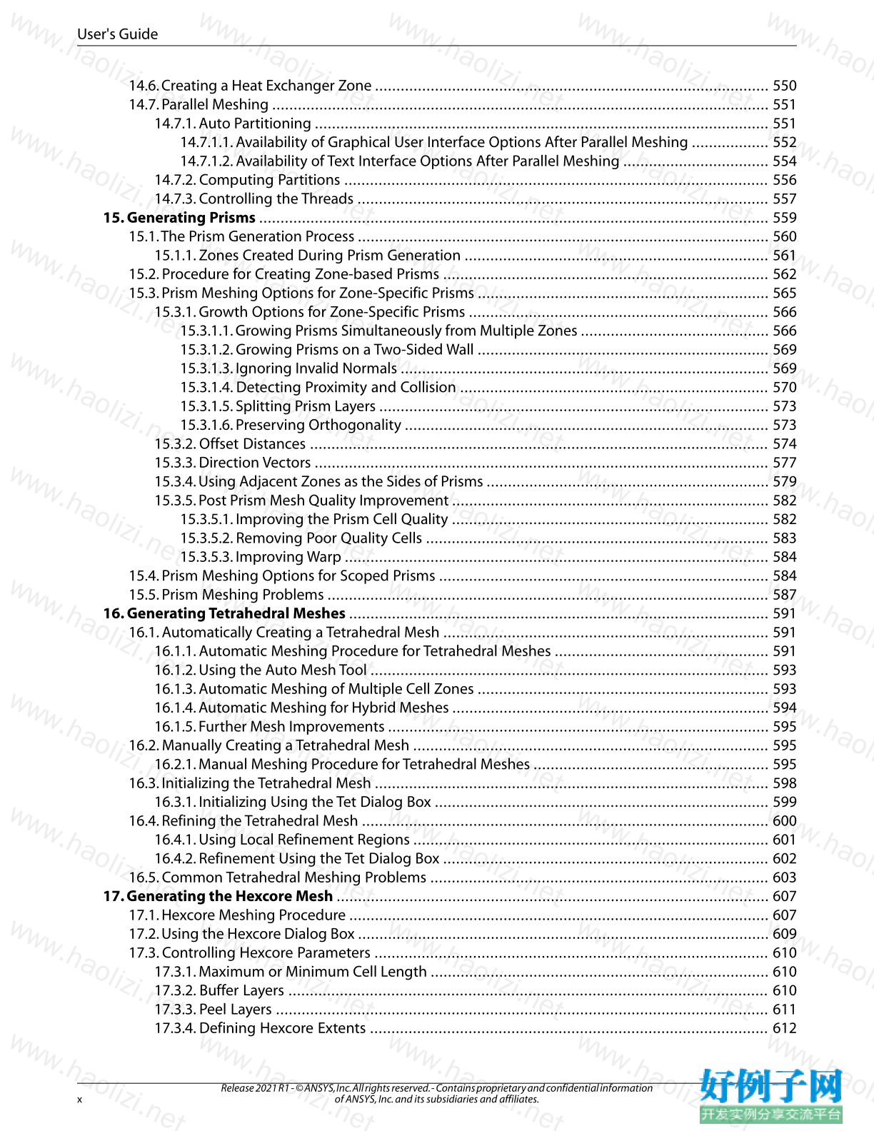
14.6. Creating a Heat Exchanger Zone ............................................................................................ 550
14.7. Parallel Meshing .................................................................................................................... 551
14.7.1. Auto Partitioning .......................................................................................................... 551
14.7.1.1. Availability of Graphical User Interface Options After Parallel Meshing .................. 552
14.7.1.2. Availability of Text Interface Options After Parallel Meshing .................................. 554
14.7.2. Computing Partitions ................................................................................................... 556
14.7.3. Controlling the Threads ................................................................................................ 557
15. Generating Prisms ....................................................................................................................... 559
15.1.The Prism Generation Process ................................................................................................ 560
15.1.1. Zones Created During Prism Generation ....................................................................... 561
15.2. Procedure for Creating Zone-based Prisms ............................................................................ 562
15.3. Prism Meshing Options for Zone-Specific Prisms .................................................................... 565
15.3.1. Growth Options for Zone-Specific Prisms ...................................................................... 566
15.3.1.1. Growing Prisms Simultaneously from Multiple Zones ............................................ 566
15.3.1.2. Growing Prisms on a Two-Sided Wall .................................................................... 569
15.3.1.3. Ignoring Invalid Normals ...................................................................................... 569
15.3.1.4. Detecting Proximity and Collision ........................................................................ 570
15.3.1.5. Splitting Prism Layers ........................................................................................... 573
15.3.1.6. Preserving Orthogonality ..................................................................................... 573
15.3.2. Offset Distances ........................................................................................................... 574
15.3.3. Direction Vectors .......................................................................................................... 577
15.3.4. Using Adjacent Zones as the Sides of Prisms .................................................................. 579
15.3.5. Post Prism Mesh Quality Improvement .......................................................................... 582
15.3.5.1. Improving the Prism Cell Quality .......................................................................... 582
15.3.5.2. Removing Poor Quality Cells ................................................................................ 583
15.3.5.3. Improving Warp ................................................................................................... 584
15.4. Prism Meshing Options for Scoped Prisms ............................................................................. 584
15.5. Prism Meshing Problems ....................................................................................................... 587
16. Generating Tetrahedral Meshes .................................................................................................. 591
16.1. Automatically Creating a Tetrahedral Mesh ............................................................................ 591
16.1.1. Automatic Meshing Procedure for Tetrahedral Meshes .................................................. 591
16.1.2. Using the Auto Mesh Tool ............................................................................................. 593
16.1.3. Automatic Meshing of Multiple Cell Zones .................................................................... 593
16.1.4. Automatic Meshing for Hybrid Meshes .......................................................................... 594
16.1.5. Further Mesh Improvements ......................................................................................... 595
16.2. Manually Creating a Tetrahedral Mesh ................................................................................... 595
16.2.1. Manual Meshing Procedure for Tetrahedral Meshes ....................................................... 595
16.3. Initializing the Tetrahedral Mesh ............................................................................................ 598
16.3.1. Initializing Using the Tet Dialog Box .............................................................................. 599
16.4. Refining the Tetrahedral Mesh ............................................................................................... 600
16.4.1. Using Local Refinement Regions ................................................................................... 601
16.4.2. Refinement Using the Tet Dialog Box ............................................................................ 602
16.5. Common Tetrahedral Meshing Problems ............................................................................... 603
17. Generating the Hexcore Mesh ..................................................................................................... 607
17.1. Hexcore Meshing Procedure .................................................................................................. 607
17.2. Using the Hexcore Dialog Box ................................................................................................ 609
17.3. Controlling Hexcore Parameters ............................................................................................ 610
17.3.1. Maximum or Minimum Cell Length ............................................................................... 610
17.3.2. Buffer Layers ................................................................................................................ 610
17.3.3. Peel Layers ................................................................................................................... 611
17.3.4. Defining Hexcore Extents ............................................................................................. 612
Release 2021 R1 - © ANSYS, Inc. All rights reserved. - Contains proprietary and confidential information
of ANSYS, Inc. and its subsidiaries and affiliates. x
User's Guide
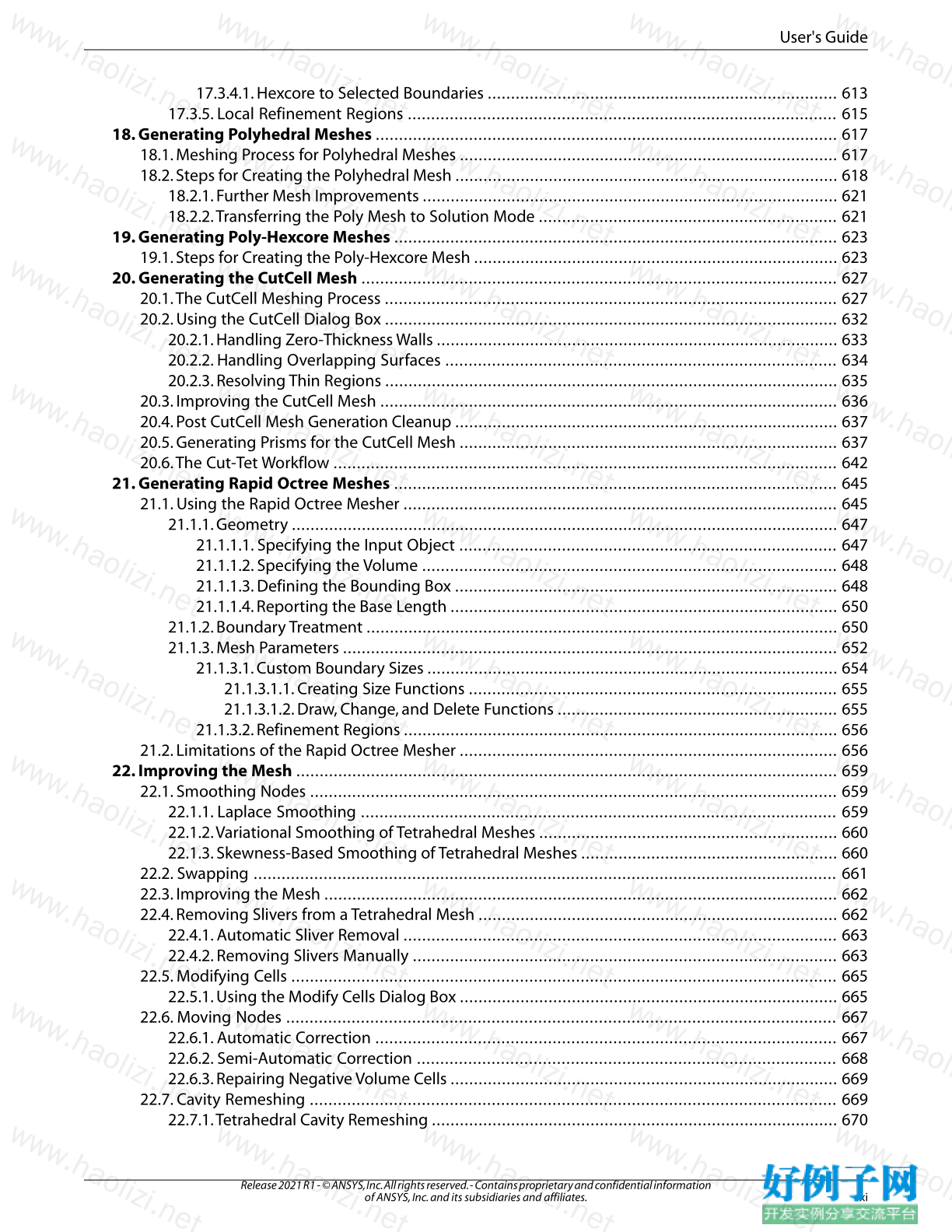
17.3.4.1. Hexcore to Selected Boundaries ........................................................................... 613
17.3.5. Local Refinement Regions ............................................................................................ 615
18. Generating Polyhedral Meshes ................................................................................................... 617
18.1. Meshing Process for Polyhedral Meshes ................................................................................. 617
18.2. Steps for Creating the Polyhedral Mesh .................................................................................. 618
18.2.1. Further Mesh Improvements ......................................................................................... 621
18.2.2.Transferring the Poly Mesh to Solution Mode ................................................................ 621
19. Generating Poly-Hexcore Meshes ............................................................................................... 623
19.1. Steps for Creating the Poly-Hexcore Mesh .............................................................................. 623
20. Generating the CutCell Mesh ...................................................................................................... 627
20.1.The CutCell Meshing Process ................................................................................................. 627
20.2. Using the CutCell Dialog Box ................................................................................................. 632
20.2.1. Handling Zero-Thickness Walls ...................................................................................... 633
20.2.2. Handling Overlapping Surfaces .................................................................................... 634
20.2.3. Resolving Thin Regions ................................................................................................. 635
20.3. Improving the CutCell Mesh .................................................................................................. 636
20.4. Post CutCell Mesh Generation Cleanup .................................................................................. 637
20.5. Generating Prisms for the CutCell Mesh ................................................................................. 637
20.6.The Cut-Tet Workflow ............................................................................................................ 642
21. Generating Rapid Octree Meshes ............................................................................................... 645
21.1. Using the Rapid Octree Mesher ............................................................................................. 645
21.1.1. Geometry ..................................................................................................................... 647
21.1.1.1. Specifying the Input Object ................................................................................. 647
21.1.1.2. Specifying the Volume ......................................................................................... 648
21.1.1.3. Defining the Bounding Box .................................................................................. 648
21.1.1.4. Reporting the Base Length ................................................................................... 650
21.1.2. Boundary Treatment ..................................................................................................... 650
21.1.3. Mesh Parameters .......................................................................................................... 652
21.1.3.1. Custom Boundary Sizes ........................................................................................ 654
21.1.3.1.1. Creating Size Functions ............................................................................... 655
21.1.3.1.2. Draw, Change, and Delete Functions ............................................................ 655
21.1.3.2. Refinement Regions ............................................................................................. 656
21.2. Limitations of the Rapid Octree Mesher ................................................................................. 656
22. Improving the Mesh .................................................................................................................... 659
22.1. Smoothing Nodes ................................................................................................................. 659
22.1.1. Laplace Smoothing ...................................................................................................... 659
22.1.2.Variational Smoothing of Tetrahedral Meshes ................................................................ 660
22.1.3. Skewness-Based Smoothing of Tetrahedral Meshes ....................................................... 660
22.2. Swapping ............................................................................................................................. 661
22.3. Improving the Mesh .............................................................................................................. 662
22.4. Removing Slivers from a Tetrahedral Mesh ............................................................................. 662
22.4.1. Automatic Sliver Removal ............................................................................................. 663
22.4.2. Removing Slivers Manually ........................................................................................... 663
22.5. Modifying Cells ..................................................................................................................... 665
22.5.1. Using the Modify Cells Dialog Box ................................................................................. 665
22.6. Moving Nodes ...................................................................................................................... 667
22.6.1. Automatic Correction ................................................................................................... 667
22.6.2. Semi-Automatic Correction .......................................................................................... 668
22.6.3. Repairing Negative Volume Cells ................................................................................... 669
22.7. Cavity Remeshing ................................................................................................................. 669
22.7.1.Tetrahedral Cavity Remeshing ....................................................................................... 670
xi
Release 2021 R1 - © ANSYS, Inc. All rights reserved. - Contains proprietary and confidential information
of ANSYS, Inc. and its subsidiaries and affiliates.
User's Guide
22.7.2. Hexcore Cavity Remeshing ........................................................................................... 672
22.8. Manipulating Cell Zones ........................................................................................................ 675
22.8.1. Active Zones and Cell Types .......................................................................................... 675
22.8.2. Copying and Moving Cell Zones .................................................................................... 676
22.9. Manipulating Cell Zone Conditions ........................................................................................ 677
22.10. Using Domains to Group and Mesh Boundary Faces ............................................................. 677
22.10.1. Using Domains ........................................................................................................... 677
22.10.2. Defining Domains ...................................................................................................... 677
22.11. Checking the Mesh ............................................................................................................. 678
22.12. Selectively Checking the Volume Mesh ................................................................................ 679
22.13. Checking the Mesh Quality .................................................................................................. 682
22.14. Clearing the Mesh ............................................................................................................... 682
23. Examining the Mesh .................................................................................................................... 685
23.1. Displaying the Mesh .............................................................................................................. 685
23.1.1. Generating the Mesh Display using Onscreen Tools ....................................................... 685
23.1.2. Generating the Mesh Display Using the Display Grid Dialog Box .................................... 687
23.1.2.1. Mesh Display Attributes ....................................................................................... 687
23.2. Controlling Display Options ................................................................................................... 690
23.3. Modifying and Saving the View ............................................................................................. 693
23.3.1. Mirroring a Non-symmetric Domain .............................................................................. 693
23.3.2. Controlling Perspective and Camera Parameters ........................................................... 693
23.4. Composing a Scene ............................................................................................................... 694
23.4.1. Changing the Display Properties ................................................................................... 695
23.4.2.Transforming Geometric Entities in a Scene ................................................................... 695
23.4.3. Adding a Bounding Frame ............................................................................................ 695
23.4.4. Using the Scene Description Dialog Box ........................................................................ 696
23.5. Controlling the Mouse Buttons .............................................................................................. 698
23.6. Controlling the Mouse Probe Function .................................................................................. 700
23.7. Annotating the Display ......................................................................................................... 702
23.8. Setting Default Controls ........................................................................................................ 702
24. Determining Mesh Statistics and Quality ................................................................................... 703
24.1. Determining Mesh Statistics .................................................................................................. 703
24.2. Determining Mesh Quality .................................................................................................... 704
24.2.1. Determining Surface Mesh Quality ............................................................................... 704
24.2.2. Determining Volume Mesh Quality ............................................................................... 705
24.2.3. Determining Boundary Cell Quality ............................................................................... 706
24.2.4. Quality Measure ........................................................................................................... 706
24.3. Reporting Mesh Information ................................................................................................. 714
A. Importing Boundary and Volume Meshes ........................................................................................ 717
A.1. GAMBIT Meshes ...................................................................................................................... 717
A.2.TetraMesher Volume Mesh ...................................................................................................... 717
A.3. Meshes from Third-Party CAD Packages .................................................................................. 717
A.3.1. I-deas Universal Files ...................................................................................................... 719
A.3.1.1. Recognized I-deas Datasets ................................................................................... 719
A.3.1.2. Grouping Elements to Create Zones for a Surface Mesh .......................................... 719
A.3.1.3. Grouping Nodes to Create Zones for a Volume Mesh .............................................. 720
A.3.1.4. Periodic Boundaries .............................................................................................. 720
A.3.1.5. Deleting Duplicate Nodes ...................................................................................... 720
A.3.2. PATRAN Neutral Files ...................................................................................................... 720
A.3.2.1. Recognized PATRAN Datasets ................................................................................ 720
A.3.2.2. Grouping Elements to Create Zones ....................................................................... 721
Release 2021 R1 - © ANSYS, Inc. All rights reserved. - Contains proprietary and confidential information
of ANSYS, Inc. and its subsidiaries and affiliates. xii
User's Guide
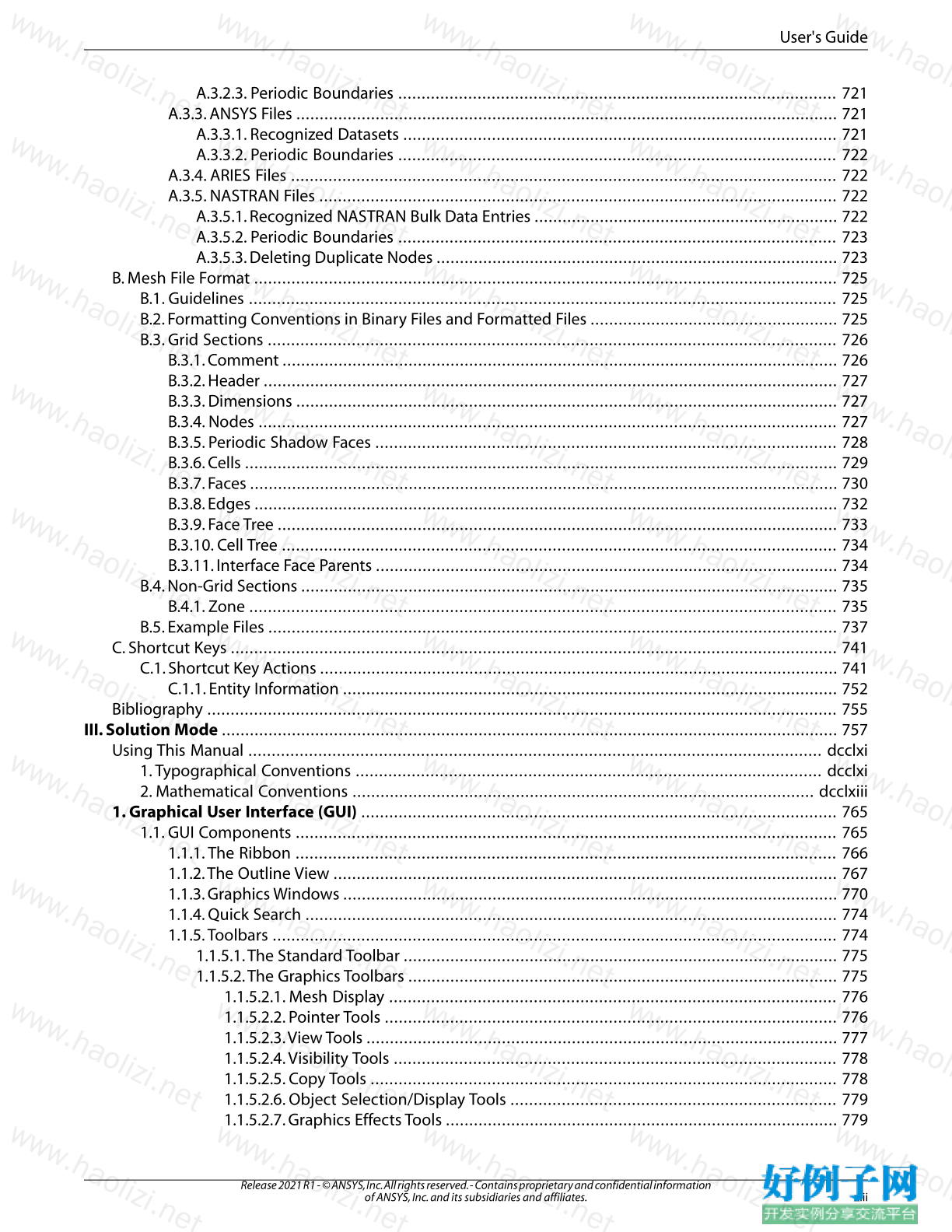
A.3.2.3. Periodic Boundaries .............................................................................................. 721
A.3.3. ANSYS Files .................................................................................................................... 721
A.3.3.1. Recognized Datasets ............................................................................................. 721
A.3.3.2. Periodic Boundaries .............................................................................................. 722
A.3.4. ARIES Files ..................................................................................................................... 722
A.3.5. NASTRAN Files ............................................................................................................... 722
A.3.5.1. Recognized NASTRAN Bulk Data Entries ................................................................. 722
A.3.5.2. Periodic Boundaries .............................................................................................. 723
A.3.5.3. Deleting Duplicate Nodes ...................................................................................... 723
B. Mesh File Format ............................................................................................................................. 725
B.1. Guidelines .............................................................................................................................. 725
B.2. Formatting Conventions in Binary Files and Formatted Files ..................................................... 725
B.3. Grid Sections .......................................................................................................................... 726
B.3.1. Comment ....................................................................................................................... 726
B.3.2. Header ........................................................................................................................... 727
B.3.3. Dimensions .................................................................................................................... 727
B.3.4. Nodes ............................................................................................................................ 727
B.3.5. Periodic Shadow Faces ................................................................................................... 728
B.3.6. Cells ............................................................................................................................... 729
B.3.7. Faces .............................................................................................................................. 730
B.3.8. Edges ............................................................................................................................. 732
B.3.9. Face Tree ........................................................................................................................ 733
B.3.10. Cell Tree ....................................................................................................................... 734
B.3.11. Interface Face Parents ................................................................................................... 734
B.4. Non-Grid Sections ................................................................................................................... 735
B.4.1. Zone .............................................................................................................................. 735
B.5. Example Files .......................................................................................................................... 737
C. Shortcut Keys .................................................................................................................................. 741
C.1. Shortcut Key Actions ............................................................................................................... 741
C.1.1. Entity Information .......................................................................................................... 752
Bibliography ....................................................................................................................................... 755
III. Solution Mode .................................................................................................................................... 757
Using This Manual ........................................................................................................................... dcclxi
1.Typographical Conventions .................................................................................................... dcclxi
2. Mathematical Conventions ................................................................................................... dcclxiii
1. Graphical User Interface (GUI) ...................................................................................................... 765
1.1. GUI Components .................................................................................................................... 765
1.1.1.The Ribbon .................................................................................................................... 766
1.1.2.The Outline View ............................................................................................................ 767
1.1.3. Graphics Windows .......................................................................................................... 770
1.1.4. Quick Search .................................................................................................................. 774
1.1.5.Toolbars ......................................................................................................................... 774
1.1.5.1.The Standard Toolbar ............................................................................................. 775
1.1.5.2.The Graphics Toolbars ............................................................................................ 775
1.1.5.2.1. Mesh Display ................................................................................................ 776
1.1.5.2.2. Pointer Tools ................................................................................................. 776
1.1.5.2.3.View Tools ..................................................................................................... 777
1.1.5.2.4.Visibility Tools ............................................................................................... 778
1.1.5.2.5. Copy Tools .................................................................................................... 778
1.1.5.2.6. Object Selection/Display Tools ...................................................................... 779
1.1.5.2.7. Graphics Effects Tools .................................................................................... 779
xiii
Release 2021 R1 - © ANSYS, Inc. All rights reserved. - Contains proprietary and confidential information
of ANSYS, Inc. and its subsidiaries and affiliates.
User's Guide
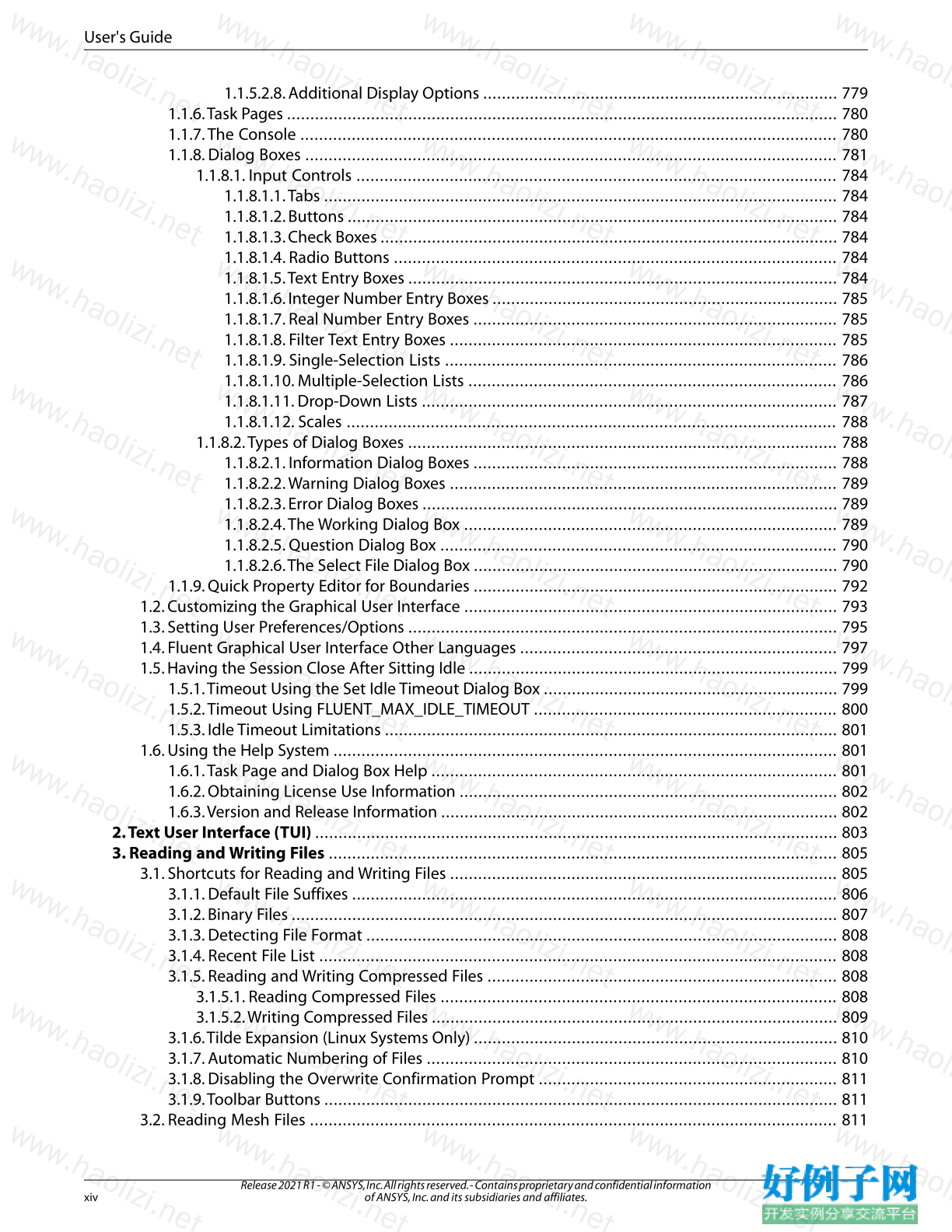
1.1.5.2.8. Additional Display Options ............................................................................ 779
1.1.6.Task Pages ...................................................................................................................... 780
1.1.7.The Console ................................................................................................................... 780
1.1.8. Dialog Boxes .................................................................................................................. 781
1.1.8.1. Input Controls ....................................................................................................... 784
1.1.8.1.1.Tabs .............................................................................................................. 784
1.1.8.1.2. Buttons ......................................................................................................... 784
1.1.8.1.3. Check Boxes .................................................................................................. 784
1.1.8.1.4. Radio Buttons ............................................................................................... 784
1.1.8.1.5.Text Entry Boxes ............................................................................................ 784
1.1.8.1.6. Integer Number Entry Boxes .......................................................................... 785
1.1.8.1.7. Real Number Entry Boxes .............................................................................. 785
1.1.8.1.8. Filter Text Entry Boxes ................................................................................... 785
1.1.8.1.9. Single-Selection Lists .................................................................................... 786
1.1.8.1.10. Multiple-Selection Lists ............................................................................... 786
1.1.8.1.11. Drop-Down Lists ......................................................................................... 787
1.1.8.1.12. Scales ......................................................................................................... 788
1.1.8.2.Types of Dialog Boxes ............................................................................................ 788
1.1.8.2.1. Information Dialog Boxes .............................................................................. 788
1.1.8.2.2.Warning Dialog Boxes ................................................................................... 789
1.1.8.2.3. Error Dialog Boxes ......................................................................................... 789
1.1.8.2.4.The Working Dialog Box ................................................................................ 789
1.1.8.2.5. Question Dialog Box ..................................................................................... 790
1.1.8.2.6.The Select File Dialog Box .............................................................................. 790
1.1.9. Quick Property Editor for Boundaries .............................................................................. 792
1.2. Customizing the Graphical User Interface ................................................................................ 793
1.3. Setting User Preferences/Options ............................................................................................ 795
1.4. Fluent Graphical User Interface Other Languages .................................................................... 797
1.5. Having the Session Close After Sitting Idle ............................................................................... 799
1.5.1.Timeout Using the Set Idle Timeout Dialog Box ............................................................... 799
1.5.2.Timeout Using FLUENT_MAX_IDLE_TIMEOUT ................................................................. 800
1.5.3. Idle Timeout Limitations ................................................................................................. 801
1.6. Using the Help System ............................................................................................................ 801
1.6.1.Task Page and Dialog Box Help ....................................................................................... 801
1.6.2. Obtaining License Use Information ................................................................................. 802
1.6.3.Version and Release Information ..................................................................................... 802
2.Text User Interface (TUI) ................................................................................................................ 803
3. Reading and Writing Files ............................................................................................................. 805
3.1. Shortcuts for Reading and Writing Files ................................................................................... 805
3.1.1. Default File Suffixes ........................................................................................................ 806
3.1.2. Binary Files ..................................................................................................................... 807
3.1.3. Detecting File Format ..................................................................................................... 808
3.1.4. Recent File List ............................................................................................................... 808
3.1.5. Reading and Writing Compressed Files ........................................................................... 808
3.1.5.1. Reading Compressed Files ..................................................................................... 808
3.1.5.2.Writing Compressed Files ....................................................................................... 809
3.1.6.Tilde Expansion (Linux Systems Only) .............................................................................. 810
3.1.7. Automatic Numbering of Files ........................................................................................ 810
3.1.8. Disabling the Overwrite Confirmation Prompt ................................................................ 811
3.1.9.Toolbar Buttons .............................................................................................................. 811
3.2. Reading Mesh Files ................................................................................................................. 811
Release 2021 R1 - © ANSYS, Inc. All rights reserved. - Contains proprietary and confidential information
of ANSYS, Inc. and its subsidiaries and affiliates. xiv
User's Guide
3.3. Reading and Writing Case and Data Files ................................................................................. 812
3.3.1. Reading and Writing Case Files ....................................................................................... 813
3.3.2. Reading and Writing Data Files ....................................................................................... 814
3.3.3. Reading and Writing Case and Data Files Together .......................................................... 815
3.3.4. Reading and Writing Files in the Legacy Format .............................................................. 815
3.3.5. Automatic Saving of Case and Data Files ......................................................................... 815
3.4. Reading Fluent/UNS and RAMPANT Case and Data Files ........................................................... 818
3.5. Reading and Writing Profile Files ............................................................................................. 819
3.5.1. Reading Profile Files ....................................................................................................... 819
3.5.2.Writing Profile Files ......................................................................................................... 819
3.6. Reading and Writing Boundary Conditions .............................................................................. 821
3.7.Writing a Boundary Mesh ........................................................................................................ 822
3.8. Reading Scheme Source Files .................................................................................................. 822
3.9. Creating and Reading Journal Files .......................................................................................... 822
3.9.1. Procedure ...................................................................................................................... 824
3.9.2. Multiple Journal Files ...................................................................................................... 825
3.10. Creating Transcript Files ........................................................................................................ 826
3.11. Importing Files ...................................................................................................................... 826
3.11.1. ABAQUS Files ............................................................................................................... 829
3.11.2. CFX Files ....................................................................................................................... 830
3.11.3. Meshes and Data in CGNS Format ................................................................................. 830
3.11.4. EnSight Files ................................................................................................................. 831
3.11.5. ANSYS FIDAP Neutral Files ............................................................................................ 832
3.11.6. GAMBIT and GeoMesh Mesh Files ................................................................................. 832
3.11.7. HYPERMESH ASCII Files ................................................................................................. 832
3.11.8. I-deas Universal Files ..................................................................................................... 832
3.11.9. LSTC Files ..................................................................................................................... 833
3.11.10. Marc POST Files .......................................................................................................... 833
3.11.11. Mechanical APDL Files ................................................................................................ 833
3.11.12. NASTRAN Files ............................................................................................................ 834
3.11.13. PATRAN Neutral Files ................................................................................................... 834
3.11.14. PLOT3D Files ............................................................................................................... 834
3.11.15. PTC Mechanica Design Files ........................................................................................ 835
3.11.16.Tecplot Files ................................................................................................................ 835
3.11.17. Fluent 4 Case Files ...................................................................................................... 835
3.11.18. PreBFC Files ................................................................................................................ 836
3.11.19. Partition Files .............................................................................................................. 836
3.11.20. CHEMKIN Mechanism ................................................................................................. 836
3.12. Exporting Solution Data ........................................................................................................ 836
3.12.1. Exporting Limitations ................................................................................................... 837
3.13. Exporting Solution Data after a Calculation ............................................................................ 838
3.13.1. ABAQUS Files ............................................................................................................... 840
3.13.2. Mechanical APDL Input Files ......................................................................................... 840
3.13.3. ASCII Files ..................................................................................................................... 841
3.13.4. AVS Files ....................................................................................................................... 841
3.13.5. CDAT for CFD-Post and EnSight ..................................................................................... 841
3.13.6. CGNS Files .................................................................................................................... 843
3.13.7. Common Fluids Format - Post Files ................................................................................ 844
3.13.8. Data Explorer Files ........................................................................................................ 845
3.13.9. EnSight Case Gold Files ................................................................................................. 845
3.13.10. FAST Files ................................................................................................................... 848
xv
Release 2021 R1 - © ANSYS, Inc. All rights reserved. - Contains proprietary and confidential information
of ANSYS, Inc. and its subsidiaries and affiliates.
User's Guide
3.13.11. FAST Solution Files ...................................................................................................... 849
3.13.12. FieldView Unstructured Files ....................................................................................... 849
3.13.13. I-deas Universal Files ................................................................................................... 850
3.13.14. NASTRAN Files ............................................................................................................ 851
3.13.15. PATRAN Files ............................................................................................................... 852
3.13.16.TAITherm Files ............................................................................................................ 852
3.13.17.Tecplot Files ................................................................................................................ 853
3.14. Exporting Steady-State Particle History Data .......................................................................... 853
3.15. Exporting Data During a Transient Calculation ....................................................................... 855
3.15.1. Creating Automatic Export Definitions for Solution Data ............................................... 857
3.15.2. Creating Automatic Export Definitions for Transient Particle History Data ...................... 859
3.16. Exporting to ANSYS CFD-Post ................................................................................................ 861
3.17. Parallel Exporting to ANSYS EnSight ...................................................................................... 862
3.18. Managing Solution Files ........................................................................................................ 864
3.19. Mesh-to-Mesh Solution Interpolation .................................................................................... 865
3.19.1. Performing Mesh-to-Mesh Solution Interpolation .......................................................... 865
3.19.2. Format of the Interpolation File ..................................................................................... 867
3.20. Mapping Data for Fluid-Structure Interaction (FSI) Applications .............................................. 868
3.20.1. FEA File Formats ........................................................................................................... 869
3.20.2. Using the FSI Mapping Dialog Boxes ............................................................................. 869
3.21. Saving Picture Files ............................................................................................................... 874
3.21.1. Using the Save Picture Dialog Box ................................................................................. 875
3.21.1.1. Choosing the Picture File Format .......................................................................... 876
3.21.1.2. Specifying the Color Mode ................................................................................... 878
3.21.1.3. Choosing the File Type ......................................................................................... 879
3.21.1.4. Defining the Resolution ....................................................................................... 879
3.21.1.5. Picture Options .................................................................................................... 879
3.21.2. Picture Options for PostScript Files ................................................................................ 879
3.21.2.1.Window Dumps (Linux Systems Only) ................................................................... 880
3.21.2.2. Previewing the Picture Image ............................................................................... 881
3.22. Setting Data File Quantities ................................................................................................... 881
3.23.The .fluent File ....................................................................................................................... 883
3.24. Coupled Simulations in ANSYS Fluent with Functional Mock-up Unit (FMU) Files .................... 883
4. Unit Systems .................................................................................................................................. 889
4.1. Restrictions on Units ............................................................................................................... 889
4.2. Units in Mesh Files .................................................................................................................. 890
4.3. Built-In Unit Systems in ANSYS Fluent ...................................................................................... 890
4.4. Customizing Units ................................................................................................................... 891
4.4.1. Listing Current Units ....................................................................................................... 891
4.4.2. Changing the Units for a Quantity ................................................................................... 891
4.4.3. Defining a New Unit ....................................................................................................... 891
4.4.3.1. Determining the Conversion Factor ........................................................................ 892
5. Fluent Expressions Language ....................................................................................................... 893
5.1. Introduction to Expressions ..................................................................................................... 893
5.1.1. Expression Syntax .......................................................................................................... 893
5.1.1.1. Expression Data Types ........................................................................................... 893
5.1.1.2. Expression Values .................................................................................................. 893
5.1.1.3. Expression Operations and Functions ..................................................................... 894
5.1.2. Units Validation .............................................................................................................. 899
5.2. Expression Sources ................................................................................................................. 899
5.2.1. Field Variables ................................................................................................................ 900
Release 2021 R1 - © ANSYS, Inc. All rights reserved. - Contains proprietary and confidential information
of ANSYS, Inc. and its subsidiaries and affiliates. xvi
User's Guide
5.2.2. Solution Variables ........................................................................................................... 900
5.2.3. Scientific Constants ........................................................................................................ 901
5.2.4. Aliases ........................................................................................................................... 901
5.2.5. Profiles ........................................................................................................................... 902
5.3. Creating and Using Expressions ............................................................................................... 903
5.3.1. Directly Applied Expressions ........................................................................................... 904
5.3.1.1. Expressions for Cell Zones and Boundary Conditions .............................................. 904
5.3.1.2. Expressions for Material Properties ......................................................................... 906
5.3.1.3. Expressions in the Console ..................................................................................... 908
5.3.2. Named Expressions ........................................................................................................ 909
5.3.3. Context Specification ..................................................................................................... 912
5.3.4. Plotting Expressions ....................................................................................................... 912
5.3.5. Postprocessing Expressions ............................................................................................ 914
5.3.6. Expression Manager ....................................................................................................... 915
5.4. Expression Examples ............................................................................................................... 915
5.4.1. Parabolic Inflow Profile ................................................................................................... 916
5.4.2.Time-Varied Parabolic Inflow ........................................................................................... 918
5.4.3. Controlled Outlet Temperature ....................................................................................... 921
5.4.4. Computing Forces with Parameterized Angle of Attack ................................................... 925
5.5. Appendix: Supported Field Variables ....................................................................................... 928
6. Reading and Manipulating Meshes .............................................................................................. 953
6.1. Mesh Topologies ..................................................................................................................... 953
6.1.1. Examples of Acceptable Mesh Topologies ....................................................................... 955
6.1.2. Face-Node Connectivity in ANSYS Fluent ........................................................................ 959
6.1.2.1. Face-Node Connectivity for Triangular Cells ............................................................ 960
6.1.2.2. Face-Node Connectivity for Quadrilateral Cells ....................................................... 961
6.1.2.3. Face-Node Connectivity for Tetrahedral Cells .......................................................... 962
6.1.2.4. Face-Node Connectivity for Wedge Cells ................................................................. 963
6.1.2.5. Face-Node Connectivity for Pyramidal Cells ............................................................ 964
6.1.2.6. Face-Node Connectivity for Hex Cells ..................................................................... 965
6.1.2.7. Face-Node Connectivity for Polyhedral Cells ........................................................... 966
6.1.3. Choosing the Appropriate Mesh Type ............................................................................. 966
6.1.3.1. Setup Time ............................................................................................................ 966
6.1.3.2. Computational Expense ......................................................................................... 967
6.1.3.3. Numerical Diffusion ............................................................................................... 968
6.2. Mesh Requirements and Considerations .................................................................................. 968
6.2.1. Geometry/Mesh Requirements ....................................................................................... 968
6.2.2. Mesh Quality .................................................................................................................. 969
6.2.2.1. Mesh Element Distribution .................................................................................... 971
6.2.2.2. Cell Quality ............................................................................................................ 972
6.2.2.3. Smoothness .......................................................................................................... 973
6.2.2.4. Flow-Field Dependency ......................................................................................... 973
6.3. Mesh Sources .......................................................................................................................... 973
6.3.1. ANSYS Meshing Mesh Files ............................................................................................. 974
6.3.2. Fluent Meshing Mode Mesh Files .................................................................................... 974
6.3.3. Fluent Meshing Mesh Files .............................................................................................. 974
6.3.4. GAMBIT Mesh Files ......................................................................................................... 974
6.3.5. GeoMesh Mesh Files ....................................................................................................... 975
6.3.6. PreBFC Mesh Files ........................................................................................................... 975
6.3.6.1. Structured Mesh Files ............................................................................................ 975
6.3.6.2. Unstructured Triangular and Tetrahedral Mesh Files ................................................ 975
xvii
Release 2021 R1 - © ANSYS, Inc. All rights reserved. - Contains proprietary and confidential information
of ANSYS, Inc. and its subsidiaries and affiliates.
User's Guide
6.3.7. ICEM CFD Mesh Files ...................................................................................................... 975
6.3.8. I-deas Universal Files ...................................................................................................... 976
6.3.8.1. Recognized I-deas Datasets .................................................................................... 976
6.3.8.2. Grouping Nodes to Create Face Zones .................................................................... 977
6.3.8.3. Grouping Elements to Create Cell Zones ................................................................. 977
6.3.8.4. Deleting Duplicate Nodes ...................................................................................... 977
6.3.9. NASTRAN Files ............................................................................................................... 977
6.3.9.1. Recognized NASTRAN Bulk Data Entries ................................................................. 977
6.3.9.2. Deleting Duplicate Nodes ...................................................................................... 978
6.3.10. PATRAN Neutral Files .................................................................................................... 978
6.3.10.1. Recognized PATRAN Datasets ............................................................................... 979
6.3.10.2. Grouping Elements to Create Cell Zones ............................................................... 979
6.3.11. Mechanical APDL Files .................................................................................................. 979
6.3.11.1. Recognized ANSYS 5.4 and 5.5 Datasets ............................................................... 980
6.3.12. CFX Files ....................................................................................................................... 980
6.3.13. Using the fe2ram Filter to Convert Files ......................................................................... 981
6.3.14. Removing Hanging Nodes/Edges ................................................................................. 982
6.3.14.1. Limitations .......................................................................................................... 982
6.3.15. Fluent/UNS and RAMPANT Case Files ............................................................................ 983
6.3.16. FLUENT 4 Case Files ...................................................................................................... 983
6.3.17. ANSYS FIDAP Neutral Files ............................................................................................ 984
6.3.18. Reading Multiple Mesh/Case/Data Files ......................................................................... 984
6.3.18.1. Reading Multiple Mesh Files via the Solution Mode of Fluent ................................ 984
6.3.18.2. Reading Multiple Mesh Files via the Meshing Mode of Fluent ................................ 985
6.3.18.3. Reading Multiple Mesh Files via tmerge ................................................................ 986
6.3.19. Reading Surface Mesh Files ........................................................................................... 988
6.4. Reference Frames .................................................................................................................... 988
6.4.1. Creating and Using Reference Frames ............................................................................. 989
6.5. Non-Conformal Meshes ........................................................................................................... 991
6.5.1. Non-Conformal Mesh Calculations .................................................................................. 992
6.5.1.1.The Periodic Boundary Condition Option ............................................................... 994
6.5.1.2.The Periodic Repeats Option .................................................................................. 996
6.5.1.3.The Coupled Wall Option ....................................................................................... 998
6.5.1.4. Matching Option ................................................................................................... 999
6.5.1.5.The Mapped Option ............................................................................................. 1000
6.5.1.6.The Static Option ................................................................................................. 1002
6.5.1.7. Interface Zones Automatic Naming Conventions .................................................. 1002
6.5.1.7.1. Default (No Options Enabled) ...................................................................... 1003
6.5.1.7.2. Periodic Boundary Condition ....................................................................... 1003
6.5.1.7.3. Periodic Repeats ......................................................................................... 1003
6.5.1.7.4. Coupled Wall ............................................................................................... 1003
6.5.1.7.5. Matching .................................................................................................... 1004
6.5.1.7.6. Mapped ...................................................................................................... 1004
6.5.1.7.7. Static .......................................................................................................... 1004
6.5.2. Non-Conformal Interface Algorithm .............................................................................. 1005
6.5.3. Requirements and Limitations of Non-Conformal Meshes .............................................. 1005
6.5.4. Using a Non-Conformal Mesh in ANSYS Fluent .............................................................. 1007
6.5.4.1. Manually Creating Mesh Interfaces ....................................................................... 1020
6.5.4.2.Transferring Motion Across a Mesh Interface ......................................................... 1022
6.6. Overset Meshes .................................................................................................................... 1023
6.6.1. Introduction ................................................................................................................. 1024
Release 2021 R1 - © ANSYS, Inc. All rights reserved. - Contains proprietary and confidential information
of ANSYS, Inc. and its subsidiaries and affiliates. xviii
User's Guide
6.6.2. Overset Topologies ....................................................................................................... 1025
6.6.3. Overset Domain Connectivity ....................................................................................... 1029
6.6.3.1. Hole Cutting ........................................................................................................ 1029
6.6.3.1.1. Hole Cutting Control ................................................................................... 1030
6.6.3.2. Overlap Minimization .......................................................................................... 1031
6.6.3.3. Donor Search ....................................................................................................... 1033
6.6.4. Diagnosing Overset Interface Issues .............................................................................. 1033
6.6.4.1. Flood Filling Fails During Hole Cutting .................................................................. 1034
6.6.4.1.1. Incorrect Seed Cells ..................................................................................... 1034
6.6.4.1.2. Leakage Between Overlapping Boundaries .................................................. 1034
6.6.4.2. Donor Search Fails Due to Orphan Cells ................................................................ 1035
6.6.5. Overset Mesh Adaption ................................................................................................ 1036
6.6.5.1. Donor Size Adaption ............................................................................................ 1036
6.6.5.2. Orphan Adaption ................................................................................................. 1036
6.6.5.3. Using Manual Overset Adaption ........................................................................... 1036
6.6.5.4. Using Dynamic Overset Adaption ......................................................................... 1037
6.6.5.5. Overset Adaption Controls ................................................................................... 1037
6.6.6. Overset Meshing Best Practices ..................................................................................... 1038
6.6.7. Overset Meshing Limitations and Compatibilities .......................................................... 1040
6.6.7.1. Limitations .......................................................................................................... 1040
6.6.7.2. Compatibilities .................................................................................................... 1040
6.6.8. Setting up an Overset Interface ..................................................................................... 1042
6.6.9. Postprocessing Overset Meshes .................................................................................... 1044
6.6.9.1. Overset Mesh Display ........................................................................................... 1044
6.6.9.2. Overset Field Functions ........................................................................................ 1045
6.6.9.3. Overset Cell Marks ............................................................................................... 1048
6.6.9.4. Overset Interface listing ....................................................................................... 1048
6.6.9.5. Overset Postprocessing Limitations ...................................................................... 1048
6.6.10.Writing and Reading Overset Files ............................................................................... 1049
6.7. Checking the Mesh ............................................................................................................... 1049
6.7.1. Mesh Check Report ...................................................................................................... 1050
6.7.2. Repairing Meshes ......................................................................................................... 1051
6.8. Reporting Mesh Statistics ...................................................................................................... 1054
6.8.1. Mesh Size ..................................................................................................................... 1054
6.8.2. Memory Usage ............................................................................................................. 1055
6.8.2.1. Linux Systems ...................................................................................................... 1055
6.8.2.2.Windows Systems ................................................................................................ 1055
6.8.3. Mesh Zone Information ................................................................................................ 1056
6.8.4. Partition Statistics ......................................................................................................... 1056
6.9. Converting the Mesh to a Polyhedral Mesh ............................................................................ 1056
6.9.1. Converting the Domain to a Polyhedra ......................................................................... 1057
6.9.1.1. Limitations .......................................................................................................... 1061
6.9.2. Converting Skewed Cells to Polyhedra .......................................................................... 1062
6.9.2.1. Limitations .......................................................................................................... 1062
6.9.3. Converting Cells with Hanging Nodes / Edges to Polyhedra ........................................... 1063
6.9.3.1. Limitations .......................................................................................................... 1063
6.10. Modifying the Mesh ............................................................................................................ 1064
6.10.1. Merging Zones ........................................................................................................... 1065
6.10.1.1.When to Merge Zones ........................................................................................ 1065
6.10.1.2. Using the Merge Zones Dialog Box ..................................................................... 1066
6.10.2. Separating Zones ....................................................................................................... 1066
xix
Release 2021 R1 - © ANSYS, Inc. All rights reserved. - Contains proprietary and confidential information
of ANSYS, Inc. and its subsidiaries and affiliates.
User's Guide
6.10.2.1. Separating Face Zones ....................................................................................... 1067
6.10.2.1.1. Methods for Separating Face Zones ........................................................... 1067
6.10.2.1.2. Inputs for Separating Face Zones ............................................................... 1067
6.10.2.2. Separating Cell Zones ........................................................................................ 1069
6.10.2.2.1. Methods for Separating Cell Zones ............................................................ 1069
6.10.2.2.2. Inputs for Separating Cell Zones ................................................................ 1069
6.10.3. Fusing Face Zones ...................................................................................................... 1071
6.10.3.1. Inputs for Fusing Face Zones .............................................................................. 1072
6.10.3.1.1. Fusing Zones on Branch Cuts ..................................................................... 1073
6.10.4. Creating Periodic Zones and Interfaces ....................................................................... 1073
6.10.5. Decoupling Periodic Zones ......................................................................................... 1076
6.10.6. Slitting Face Zones ...................................................................................................... 1077
6.10.6.1. Inputs for Slitting Face Zones ............................................................................. 1078
6.10.7. Orienting Face Zones .................................................................................................. 1078
6.10.8. Extruding Face Zones ................................................................................................. 1078
6.10.8.1. Specifying Extrusion by Displacement Distances ................................................. 1079
6.10.8.2. Specifying Extrusion by Parametric Coordinates ................................................. 1079
6.10.9. Replacing, Deleting, Deactivating, and Activating Zones .............................................. 1079
6.10.9.1. Replacing Zones ................................................................................................ 1079
6.10.9.2. Deleting Zones .................................................................................................. 1081
6.10.9.3. Deactivating Zones ............................................................................................ 1081
6.10.9.4. Activating Zones ................................................................................................ 1082
6.10.10. Copying Cell Zones ................................................................................................... 1083
6.10.11. Replacing the Mesh .................................................................................................. 1083
6.10.11.1. Inputs for Replacing the Mesh .......................................................................... 1084
6.10.11.2. Limitations ....................................................................................................... 1085
6.10.12. Managing Adjacent Zones ........................................................................................ 1085
6.10.12.1. Renaming Zones Using the Adjacency Dialog Box ............................................. 1086
6.10.13. Reordering the Domain ............................................................................................ 1087
6.10.14. Scaling the Mesh ...................................................................................................... 1088
6.10.14.1. Scaling the Entire Mesh .................................................................................... 1088
6.10.14.1.1. Changing the Unit of Length ................................................................... 1089
6.10.14.1.2. Unscaling the Mesh ................................................................................. 1089
6.10.14.1.3. Changing the Physical Size of the Mesh .................................................... 1090
6.10.14.2. Scaling Individual Cell Zones ............................................................................ 1090
6.10.15.Translating the Mesh ................................................................................................. 1090
6.10.15.1.Translating the Entire Mesh .............................................................................. 1090
6.10.15.2.Translating Individual Cell Zones ...................................................................... 1091
6.10.16. Rotating the Mesh .................................................................................................... 1091
6.10.16.1. Rotating the Entire Mesh .................................................................................. 1092
6.10.16.2. Rotating Individual Cell Zones .......................................................................... 1092
6.10.17. Improving the Mesh by Smoothing and Swapping .................................................... 1093
6.10.17.1. Smoothing ....................................................................................................... 1093
6.10.17.1.1. Quality-Based Smoothing ........................................................................ 1094
6.10.17.1.2. Laplacian Smoothing ............................................................................... 1095
6.10.17.1.3. Skewness-Based Smoothing .................................................................... 1097
6.10.17.2. Face Swapping ................................................................................................. 1098
6.10.17.2.1.Triangular Meshes ................................................................................... 1098
6.10.17.2.2.Tetrahedral Meshes ................................................................................. 1099
6.10.17.3. Combining Skewness-Based Smoothing and Face Swapping ............................ 1099
7. Cell Zone and Boundary Conditions ........................................................................................... 1101
Release 2021 R1 - © ANSYS, Inc. All rights reserved. - Contains proprietary and confidential information
of ANSYS, Inc. and its subsidiaries and affiliates. xx
User's Guide
7.1. Overview .............................................................................................................................. 1101
7.1.1. Available Cell Zone and Boundary Types ....................................................................... 1102
7.1.2.The Cell Zone and Boundary Conditions Task Pages ....................................................... 1102
7.1.3. Changing Cell and Boundary Zone Types ...................................................................... 1103
7.1.4. Setting Cell Zone and Boundary Conditions .................................................................. 1105
7.1.5. Copying Cell Zone and Boundary Conditions ................................................................ 1106
7.1.6. Changing Cell or Boundary Zone Names ....................................................................... 1107
7.1.7. Defining Non-Uniform Cell Zone and Boundary Conditions ........................................... 1108
7.1.8. Defining and Viewing Parameters ................................................................................. 1108
7.1.8.1. Creating a New Parameter .................................................................................... 1111
7.1.8.2.Working With Advanced Parameter Options ......................................................... 1113
7.1.8.2.1. Defining Scheme Procedures With Input Parameters .................................... 1113
7.1.8.2.2. Defining UDFs With Input Parameters .......................................................... 1115
7.1.8.2.3. Using the Text User Interface to Define UDFs and Scheme Procedures With Input
Parameters ............................................................................................................... 1116
7.1.9. Selecting Cell or Boundary Zones in the Graphics Display .............................................. 1117
7.1.10. Operating and Periodic Conditions ............................................................................. 1119
7.1.11. Highlighting Selected Boundary Zones ....................................................................... 1120
7.1.12. Saving and Reusing Cell Zone and Boundary Conditions ............................................. 1120
7.2. Cell Zone Conditions ............................................................................................................. 1120
7.2.1. Fluid Conditions ........................................................................................................... 1121
7.2.1.1. Inputs for Fluid Zones .......................................................................................... 1121
7.2.1.1.1. Defining the Fluid Material .......................................................................... 1122
7.2.1.1.2. Defining Sources ......................................................................................... 1122
7.2.1.1.3. Defining Fixed Values .................................................................................. 1122
7.2.1.1.4. Specifying a Laminar Zone .......................................................................... 1123
7.2.1.1.5. Specifying a Reaction Mechanism ................................................................ 1123
7.2.1.1.6. Specifying the Rotation Axis ........................................................................ 1123
7.2.1.1.7. Defining Zone Motion ................................................................................. 1124
7.2.1.1.8. Defining Radiation Parameters .................................................................... 1126
7.2.2. Solid Conditions ........................................................................................................... 1126
7.2.2.1. Inputs for Solid Zones .......................................................................................... 1126
7.2.2.1.1. Defining the Solid Material .......................................................................... 1127
7.2.2.1.2. Defining a Heat Source ................................................................................ 1127
7.2.2.1.3. Defining a Fixed Temperature ...................................................................... 1127
7.2.2.1.4. Specifying the Rotation Axis for Boundary Zones ......................................... 1127
7.2.2.1.5. Defining Zone Motion ................................................................................. 1128
7.2.2.1.6. Defining Radiation Parameters .................................................................... 1133
7.2.3. Porous Media Conditions .............................................................................................. 1133
7.2.3.1. Limitations and Assumptions of the Porous Media Model ..................................... 1134
7.2.3.2. Momentum Equations for Porous Media ............................................................... 1135
7.2.3.2.1. Darcy’s Law in Porous Media ........................................................................ 1135
7.2.3.2.2. Inertial Losses in Porous Media .................................................................... 1136
7.2.3.3. Relative Viscosity in Porous Media ........................................................................ 1137
7.2.3.4.Treatment of the Energy Equation in Porous Media ............................................... 1137
7.2.3.4.1. Equilibrium Thermal Model Equations ......................................................... 1137
7.2.3.4.2. Non-Equilibrium Thermal Model Equations .................................................. 1138
7.2.3.5.Treatment of Turbulence in Porous Media ............................................................. 1139
7.2.3.6. Effect of Porosity on Transient Scalar Equations .................................................... 1139
7.2.3.7. Modeling Porous Media Based on Physical Velocity ............................................... 1139
7.2.3.7.1. Single Phase Porous Media .......................................................................... 1140
xxi
Release 2021 R1 - © ANSYS, Inc. All rights reserved. - Contains proprietary and confidential information
of ANSYS, Inc. and its subsidiaries and affiliates.
User's Guide
7.2.3.7.2. Multiphase Porous Media ............................................................................ 1140
7.2.3.7.2.1.The Continuity Equation ..................................................................... 1141
7.2.3.7.2.2.The Momentum Equation ................................................................... 1141
7.2.3.7.2.3.The Energy Equation ........................................................................... 1141
7.2.3.8. User Inputs for Porous Media ............................................................................... 1142
7.2.3.8.1. Defining the Porous Zone ............................................................................ 1144
7.2.3.8.2. Defining the Porous Velocity Formulation .................................................... 1144
7.2.3.8.3. Defining the Fluid Passing Through the Porous Medium ............................... 1144
7.2.3.8.4. Enabling Reactions in a Porous Zone ........................................................... 1144
7.2.3.8.5. Including the Relative Velocity Resistance Formulation ................................. 1145
7.2.3.8.6. Defining the Viscous and Inertial Resistance Coefficients .............................. 1145
7.2.3.8.7. Deriving Porous Media Inputs Based on Superficial Velocity, Using a Known
Pressure Loss ............................................................................................................ 1149
7.2.3.8.8. Using the Ergun Equation to Derive Porous Media Inputs for a Packed Bed .... 1150
7.2.3.8.9. Using an Empirical Equation to Derive Porous Media Inputs for Turbulent Flow
Through a Perforated Plate ........................................................................................ 1150
7.2.3.8.10. Using Tabulated Data to Derive Porous Media Inputs for Laminar Flow Through
a Fibrous Mat ............................................................................................................ 1151
7.2.3.8.11. Deriving the Porous Coefficients Based on Experimental Pressure and Velocity
Data ......................................................................................................................... 1151
7.2.3.8.12. Using the Power-Law Model ...................................................................... 1153
7.2.3.8.13. Defining Porosity ....................................................................................... 1153
7.2.3.8.14. Specifying the Heat Transfer Settings ......................................................... 1153
7.2.3.8.14.1. Equilibrium Thermal Model ............................................................... 1153
7.2.3.8.14.2. Non-Equilibrium Thermal Model ....................................................... 1154
7.2.3.8.15. Specifying the Relative Viscosity ................................................................ 1156
7.2.3.8.16. Specifying the Relative Permeability .......................................................... 1156
7.2.3.8.17. Specifying the Capillary Pressure ............................................................... 1160
7.2.3.8.17.1. Brooks-Corey Model ......................................................................... 1161
7.2.3.8.17.2.Van-Genuchten Model ...................................................................... 1161
7.2.3.8.17.3. Leverett J-Function ........................................................................... 1162
7.2.3.8.17.4. Skjaeveland Model ........................................................................... 1162
7.2.3.8.17.5. Capillary Pressure Data in a Tabular Format ....................................... 1163
7.2.3.8.17.5.1. Specifying Variables in a Tabular Format ................................... 1164
7.2.3.8.17.6. Capillary Pressure Usage ................................................................... 1165
7.2.3.8.18. Defining Sources ....................................................................................... 1167
7.2.3.8.19. Defining Fixed Values ................................................................................ 1168
7.2.3.8.20. Suppressing the Turbulent Viscosity in the Porous Region .......................... 1168
7.2.3.8.21. Specifying the Rotation Axis and Defining Zone Motion ............................. 1168
7.2.3.9. Solution Strategies for Porous Media .................................................................... 1168
7.2.3.10. Postprocessing for Porous Media ........................................................................ 1169
7.2.4. 3D Fan Zones ............................................................................................................... 1170
7.2.4.1. Momentum Equations for 3D Fan Zones ............................................................... 1170
7.2.4.2. User Inputs for 3D Fan Zones ................................................................................ 1172
7.2.4.2.1. Defining the Geometry of a 3D Fan Zone ..................................................... 1172
7.2.4.2.2. Defining the Properties of a 3D Fan Zone ..................................................... 1173
7.2.4.3. 3D Fan Zone Limitations ...................................................................................... 1174
7.2.5. Fixing the Values of Variables ........................................................................................ 1174
7.2.5.1. Overview of Fixing the Value of a Variable ............................................................. 1175
7.2.5.1.1.Variables That Can Be Fixed ......................................................................... 1176
7.2.5.2. Procedure for Fixing Values of Variables in a Zone ................................................. 1177
Release 2021 R1 - © ANSYS, Inc. All rights reserved. - Contains proprietary and confidential information
of ANSYS, Inc. and its subsidiaries and affiliates. xxii
User's Guide
7.2.5.2.1. Fixing Velocity Components ........................................................................ 1177
7.2.5.2.2. Fixing Temperature and Enthalpy ................................................................ 1178
7.2.5.2.3. Fixing Species Mass Fractions ...................................................................... 1178
7.2.5.2.4. Fixing Turbulence Quantities ....................................................................... 1178
7.2.5.2.5. Fixing User-Defined Scalars ......................................................................... 1179
7.2.6. Locking the Temperature for Solid and Shell Zones ........................................................ 1179
7.2.7. Defining Mass, Momentum, Energy, and Other Sources .................................................. 1179
7.2.7.1. Sign Conventions and Units ................................................................................. 1180
7.2.7.2. Procedure for Defining Sources ............................................................................ 1180
7.2.7.2.1. Mass Sources .............................................................................................. 1181
7.2.7.2.2. Momentum Sources .................................................................................... 1182
7.2.7.2.3. Energy Sources ........................................................................................... 1182
7.2.7.2.4.Turbulence Sources ..................................................................................... 1182
7.2.7.2.4.1. Turbulence Sources for the k- ε Model ................................................. 1182
7.2.7.2.4.2.Turbulence Sources for the Spalart-Allmaras Model ............................. 1182
7.2.7.2.4.3. Turbulence Sources for the k- ω Model ................................................ 1182
7.2.7.2.4.4.Turbulence Sources for the Reynolds Stress Model .............................. 1182
7.2.7.2.5. Mean Mixture Fraction and Variance Sources ............................................... 1183
7.2.7.2.6. P-1 Radiation Sources .................................................................................. 1183
7.2.7.2.7. Progress Variable Sources ............................................................................ 1183
7.2.7.2.8. NO, HCN, and NH3 Sources for the NOx Model .............................................. 1183
7.2.7.2.9. User-Defined Scalar (UDS) Sources ............................................................... 1183
7.3. Operating Conditions ............................................................................................................ 1184
7.3.1. Buoyancy-Driven Flows and Natural Convection ........................................................... 1184
7.3.1.1. Modeling Natural Convection in a Closed Domain ................................................ 1184
7.3.1.2.The Boussinesq Model ......................................................................................... 1184
7.3.1.3. Limitations of the Boussinesq Model .................................................................... 1185
7.3.1.4. Steps in Solving Buoyancy-Driven Flow Problems ................................................. 1185
7.3.1.5. If you are using the incompressible ideal gas law, check that the Operating Dens-
ity ................................................................................................................................... 1187
7.3.1.5.1. Setting the Operating Density for a Single Phase Flow ................................. 1187
7.3.1.5.2. Setting the Operating Density for a Multiphase Flow .................................... 1188
7.3.1.6. Solution Strategies for Buoyancy-Driven Flows ..................................................... 1188
7.3.1.6.1. Guidelines for Solving High-Rayleigh-Number Flows .................................... 1188
7.4. Boundary Conditions ............................................................................................................ 1189
7.4.1. Flow Inlet and Exit Boundary Conditions ....................................................................... 1190
7.4.2. Using Flow Boundary Conditions .................................................................................. 1190
7.4.2.1. Determining Turbulence Parameters .................................................................... 1191
7.4.2.1.1. Specification of Turbulence Quantities Using Profiles ................................... 1191
7.4.2.1.2. Uniform Specification of Turbulence Quantities ........................................... 1192
7.4.2.1.3.Turbulence Intensity .................................................................................... 1192
7.4.2.1.4.Turbulence Length Scale and Hydraulic Diameter ......................................... 1193
7.4.2.1.5.Turbulent Viscosity Ratio ............................................................................. 1194
7.4.2.1.6. Relationships for Deriving Turbulence Quantities ......................................... 1194
7.4.2.1.7. Estimating Modified Turbulent Viscosity from Turbulence Intensity and Length
Scale ......................................................................................................................... 1194
7.4.2.1.8. Estimating Turbulent Kinetic Energy from Turbulence Intensity .................... 1194
7.4.2.1.9. Estimating Turbulent Dissipation Rate from a Length Scale ........................... 1195
7.4.2.1.10. Estimating Turbulent Dissipation Rate from Turbulent Viscosity Ratio ......... 1195
7.4.2.1.11. Estimating Turbulent Dissipation Rate for Decaying Turbulence .................. 1195
7.4.2.1.12. Estimating Specific Dissipation Rate from a Length Scale ............................ 1196
xxiii
Release 2021 R1 - © ANSYS, Inc. All rights reserved. - Contains proprietary and confidential information
of ANSYS, Inc. and its subsidiaries and affiliates.
User's Guide
7.4.2.1.13. Estimating Specific Dissipation Rate from Turbulent Viscosity Ratio ............ 1196
7.4.2.1.14. Estimating Reynolds Stress Components from Turbulent Kinetic Energy ..... 1196
7.4.2.1.15. Specifying Inlet Turbulence for LES ............................................................ 1196
7.4.3. Pressure Inlet Boundary Conditions .............................................................................. 1197
7.4.3.1. Inputs at Pressure Inlet Boundaries ....................................................................... 1197
7.4.3.1.1. Summary .................................................................................................... 1197
7.4.3.1.1.1. Pressure Inputs and Hydrostatic Head ................................................. 1198
7.4.3.1.1.2. Defining Total Pressure and Temperature ............................................ 1199
7.4.3.1.1.3. Defining the Flow Direction ................................................................ 1200
7.4.3.1.1.4. Defining Static Pressure ...................................................................... 1203
7.4.3.1.1.5. Prevent Reverse Flow .......................................................................... 1203
7.4.3.1.1.6. Defining Turbulence Parameters ......................................................... 1204
7.4.3.1.1.7. Defining Radiation Parameters ............................................................ 1204
7.4.3.1.1.8. Defining Species Mass or Mole Fractions ............................................. 1204
7.4.3.1.1.9. Defining Non-Premixed Combustion Parameters ................................. 1204
7.4.3.1.1.10. Defining Premixed Combustion Boundary Conditions ....................... 1204
7.4.3.1.1.11. Defining Discrete Phase Boundary Conditions ................................... 1204
7.4.3.1.1.12. Defining Multiphase Boundary Conditions ........................................ 1204
7.4.3.1.1.13. Defining Open Channel Boundary Conditions ................................... 1204
7.4.3.2. Default Settings at Pressure Inlet Boundaries ........................................................ 1204
7.4.3.3. Calculation Procedure at Pressure Inlet Boundaries ............................................... 1205
7.4.3.3.1. Incompressible Flow Calculations at Pressure Inlet Boundaries ..................... 1205
7.4.3.3.2. Compressible Flow Calculations at Pressure Inlet Boundaries ........................ 1205
7.4.4.Velocity Inlet Boundary Conditions ............................................................................... 1206
7.4.4.1. Inputs at Velocity Inlet Boundaries ........................................................................ 1206
7.4.4.1.1. Summary .................................................................................................... 1206
7.4.4.1.2. Defining the Velocity ................................................................................... 1207
7.4.4.1.3. Setting the Velocity Magnitude and Direction .............................................. 1208
7.4.4.1.4. Setting the Velocity Magnitude Normal to the Boundary .............................. 1208
7.4.4.1.5. Setting the Velocity Components ................................................................ 1208
7.4.4.1.6. Setting the Angular Velocity ........................................................................ 1209
7.4.4.1.7. Defining Static Pressure ............................................................................... 1209
7.4.4.1.8. Defining the Temperature ........................................................................... 1209
7.4.4.1.9. Defining Outflow Gauge Pressure ................................................................ 1210
7.4.4.1.10. Defining Turbulence Parameters ................................................................ 1210
7.4.4.1.11. Defining Radiation Parameters .................................................................. 1210
7.4.4.1.12. Defining Species Mass or Mole Fractions .................................................... 1210
7.4.4.1.13. Defining Non-Premixed Combustion Parameters ....................................... 1210
7.4.4.1.14. Defining Premixed Combustion Boundary Conditions ................................ 1210
7.4.4.1.15. Defining Discrete Phase Boundary Conditions ............................................ 1210
7.4.4.1.16. Defining Multiphase Boundary Conditions ................................................. 1210
7.4.4.2. Default Settings at Velocity Inlet Boundaries ......................................................... 1210
7.4.4.3. Calculation Procedure at Velocity Inlet Boundaries ................................................ 1211
7.4.4.3.1.Treatment of Velocity Inlet Conditions at Flow Inlets ..................................... 1211
7.4.4.3.2.Treatment of Velocity Inlet Conditions at Flow Exits ...................................... 1211
7.4.4.3.3. Density Calculation ..................................................................................... 1212
7.4.5. Mass-Flow Inlet Boundary Conditions ........................................................................... 1212
7.4.5.1. Limitations and Special Considerations ................................................................ 1212
7.4.5.2. Inputs at Mass-Flow Inlet Boundaries ................................................................... 1213
7.4.5.2.1. Summary .................................................................................................... 1213
7.4.5.2.2. Selecting the Reference Frame .................................................................... 1214
Release 2021 R1 - © ANSYS, Inc. All rights reserved. - Contains proprietary and confidential information
of ANSYS, Inc. and its subsidiaries and affiliates. xxiv
User's Guide
7.4.5.2.3. Defining the Mass Flow Rate or Mass Flux .................................................... 1214
7.4.5.2.4. More About Mass Flux and Average Mass Flux ............................................. 1215
7.4.5.2.5. Defining the Total Temperature ................................................................... 1215
7.4.5.2.6. Defining Static Pressure ............................................................................... 1216
7.4.5.2.7. Defining the Flow Direction ......................................................................... 1217
7.4.5.2.8. Defining Turbulence Parameters .................................................................. 1218
7.4.5.2.9. Defining Radiation Parameters .................................................................... 1218
7.4.5.2.10. Defining Species Mass or Mole Fractions .................................................... 1218
7.4.5.2.11. Defining Non-Premixed Combustion Parameters ....................................... 1218
7.4.5.2.12. Defining Premixed Combustion Boundary Conditions ................................ 1218
7.4.5.2.13. Defining Discrete Phase Boundary Conditions ............................................ 1218
7.4.5.2.14. Defining Open Channel Boundary Conditions ............................................ 1218
7.4.5.3. Default Settings at Mass-Flow Inlet Boundaries ..................................................... 1218
7.4.5.4. Calculation Procedure at Mass-Flow Inlet Boundaries ............................................ 1219
7.4.5.4.1. Flow Calculations at Mass Flow Boundaries for Ideal Gases ........................... 1219
7.4.5.4.2. Flow Calculations at Mass Flow Boundaries for Incompressible Flows ........... 1220
7.4.5.4.3. Flux Calculations at Mass Flow Boundaries ................................................... 1220
7.4.6. Mass-Flow Outlet Boundary Conditions ........................................................................ 1220
7.4.6.1. Limitations .......................................................................................................... 1220
7.4.6.2. Inputs at Mass-Flow Outlet Boundaries ................................................................. 1220
7.4.6.2.1. Summary .................................................................................................... 1220
7.4.6.2.2. Selecting the Reference Frame .................................................................... 1221
7.4.6.2.3. Defining the Mass Flow Rate or Mass Flux .................................................... 1221
7.4.6.2.4. Defining Radiation Parameters .................................................................... 1222
7.4.6.2.5. Defining Discrete Phase Boundary Conditions ............................................. 1223
7.4.6.3. Default Settings at Mass-Flow Outlet Boundaries .................................................. 1223
7.4.6.4. Calculation Procedure at Mass-Flow Outlet Boundaries ......................................... 1223
7.4.6.4.1. Exit Corrected Mass Flow Rate ..................................................................... 1223
7.4.7. Inlet Vent Boundary Conditions .................................................................................... 1224
7.4.7.1. Inputs at Inlet Vent Boundaries ............................................................................. 1224
7.4.7.1.1. Specifying the Loss Coefficient .................................................................... 1226
7.4.8. Intake Fan Boundary Conditions ................................................................................... 1226
7.4.8.1. Inputs at Intake Fan Boundaries ........................................................................... 1226
7.4.8.1.1. Specifying the Pressure Jump ...................................................................... 1228
7.4.9. Pressure Outlet Boundary Conditions ............................................................................ 1228
7.4.9.1. Inputs at Pressure Outlet Boundaries .................................................................... 1228
7.4.9.1.1. Summary .................................................................................................... 1228
7.4.9.1.2. Defining Static Pressure ............................................................................... 1230
7.4.9.1.3. Defining Backflow Conditions ...................................................................... 1231
7.4.9.1.3.1. Prevent Reverse Flow .......................................................................... 1232
7.4.9.1.4. Defining Radiation Parameters .................................................................... 1232
7.4.9.1.5. Defining Discrete Phase Boundary Conditions ............................................. 1232
7.4.9.1.6. Defining Open Channel Boundary Conditions .............................................. 1233
7.4.9.2. Default Settings at Pressure Outlet Boundaries ..................................................... 1233
7.4.9.3. Calculation Procedure at Pressure Outlet Boundaries ............................................ 1233
7.4.9.3.1. Average Pressure Specification .................................................................... 1233
7.4.9.3.1.1. Strong Averaging ............................................................................... 1234
7.4.9.3.1.2.Weak Averaging .................................................................................. 1234
7.4.9.4. Other Optional Inputs at Pressure Outlet Boundaries ............................................ 1235
7.4.9.4.1. Non-Reflecting Boundary Conditions Option ............................................... 1235
7.4.9.4.2.Target Mass Flow Rate Option ...................................................................... 1235
xxv
Release 2021 R1 - © ANSYS, Inc. All rights reserved. - Contains proprietary and confidential information
of ANSYS, Inc. and its subsidiaries and affiliates.
User's Guide
7.4.10. Pressure Far-Field Boundary Conditions ...................................................................... 1238
7.4.10.1. Limitations ........................................................................................................ 1238
7.4.10.2. Inputs at Pressure Far-Field Boundaries ............................................................... 1238
7.4.10.2.1. Summary .................................................................................................. 1238
7.4.10.2.2. Defining Static Pressure, Mach Number, and Static Temperature ................. 1239
7.4.10.2.3. Defining the Flow Direction ....................................................................... 1239
7.4.10.2.4. Defining Turbulence Parameters ................................................................ 1240
7.4.10.2.5. Defining Radiation Parameters .................................................................. 1240
7.4.10.2.6. Defining Species Transport Parameters ...................................................... 1240
7.4.10.3. Defining Discrete Phase Boundary Conditions .................................................... 1240
7.4.10.4. Default Settings at Pressure Far-Field Boundaries ................................................ 1240
7.4.10.5. Calculation Procedure at Pressure Far-Field Boundaries ....................................... 1241
7.4.11. Outflow Boundary Conditions ..................................................................................... 1241
7.4.11.1. ANSYS Fluent’s Treatment at Outflow Boundaries ............................................... 1242
7.4.11.2. Using Outflow Boundaries .................................................................................. 1242
7.4.11.3. Mass Flow Split Boundary Conditions ................................................................. 1244
7.4.11.4. Other Inputs at Outflow Boundaries ................................................................... 1244
7.4.11.4.1. Radiation Inputs at Outflow Boundaries ..................................................... 1244
7.4.11.4.2. Defining Discrete Phase Boundary Conditions ............................................ 1245
7.4.12. Outlet Vent Boundary Conditions ................................................................................ 1245
7.4.12.1. Inputs at Outlet Vent Boundaries ........................................................................ 1245
7.4.12.1.1. Specifying the Loss Coefficient .................................................................. 1246
7.4.13. Exhaust Fan Boundary Conditions ............................................................................... 1247
7.4.13.1. Inputs at Exhaust Fan Boundaries ....................................................................... 1247
7.4.13.1.1. Specifying the Pressure Jump .................................................................... 1248
7.4.14. Degassing Boundary Conditions ................................................................................. 1249
7.4.14.1. Limitations ........................................................................................................ 1250
7.4.14.2. Inputs at Degassing Boundaries ......................................................................... 1250
7.4.15.Wall Boundary Conditions ........................................................................................... 1250
7.4.15.1. Inputs at Wall Boundaries ................................................................................... 1250
7.4.15.1.1. Summary .................................................................................................. 1250
7.4.15.2.Wall Motion ....................................................................................................... 1251
7.4.15.2.1. Defining a Stationary Wall .......................................................................... 1252
7.4.15.2.2.Velocity Conditions for Moving Walls ......................................................... 1252
7.4.15.2.3. Shear Conditions at Walls .......................................................................... 1254
7.4.15.2.4. No-Slip Walls ............................................................................................. 1254
7.4.15.2.5. Specified Shear ......................................................................................... 1254
7.4.15.2.6. Specularity Coefficient .............................................................................. 1255
7.4.15.2.7. Marangoni Stress ...................................................................................... 1256
7.4.15.2.8.Wall Roughness Effects in Turbulent Wall-Bounded Flows ........................... 1257
7.4.15.2.8.1. Standard Law-of-the-Wall Modified for Roughness ............................ 1257
7.4.15.2.8.1.1. Setting the Roughness Parameters ........................................... 1261
7.4.15.2.8.2. Additional Roughness Models for Icing Simulations ........................... 1262
7.4.15.2.8.2.1. Specified Roughness ................................................................ 1262
7.4.15.2.8.2.2. NASA Correlation ..................................................................... 1263
7.4.15.2.8.2.3. Shin-et-al ................................................................................. 1263
7.4.15.2.8.2.4. ICE3D Roughness File ............................................................... 1263
7.4.15.3.Thermal Boundary Conditions at Walls ................................................................ 1264
7.4.15.3.1. Heat Flux Boundary Conditions ................................................................. 1265
7.4.15.3.2.Temperature Boundary Conditions ............................................................ 1265
7.4.15.3.3. Convective Heat Transfer Boundary Conditions .......................................... 1265
Release 2021 R1 - © ANSYS, Inc. All rights reserved. - Contains proprietary and confidential information
of ANSYS, Inc. and its subsidiaries and affiliates. xxvi
User's Guide
7.4.15.3.4. External Radiation Boundary Conditions .................................................... 1265
7.4.15.3.5. Combined Convection and External Radiation Boundary Conditions .......... 1265
7.4.15.3.6. Augmented Heat Transfer .......................................................................... 1266
7.4.15.3.7.Thin-Wall Thermal Resistance Parameters ................................................... 1266
7.4.15.3.8.Thermal Conditions for Two-Sided Walls ..................................................... 1268
7.4.15.3.8.1. Orthogonality-Based Secondary Gradient Limiting at Coupled Two-Sided
Walls ................................................................................................................... 1269
7.4.15.3.9. Shell Conduction ....................................................................................... 1270
7.4.15.3.10. Heat Transfer Boundary Conditions Through System Coupling .................. 1271
7.4.15.3.11. Heat Transfer Boundary Conditions Across a Mapped Interface ................. 1271
7.4.15.4. Species Boundary Conditions for Walls ............................................................... 1272
7.4.15.4.1. Reaction Boundary Conditions for Walls ..................................................... 1274
7.4.15.5. Radiation Boundary Conditions for Walls ............................................................ 1274
7.4.15.6. Discrete Phase Model (DPM) Boundary Conditions for Walls ................................ 1274
7.4.15.6.1.Wall Adhesion Contact Angle for VOF Model .............................................. 1274
7.4.15.7. User-Defined Scalar (UDS) Boundary Conditions for Walls ................................... 1274
7.4.15.8.Wall Film Conditions for Walls ............................................................................. 1274
7.4.15.9. Structural Model Conditions for Walls ................................................................. 1275
7.4.15.10. Default Settings at Wall Boundaries .................................................................. 1275
7.4.15.11. Shear-Stress Calculation Procedure at Wall Boundaries ...................................... 1275
7.4.15.11.1. Shear-Stress Calculation in Laminar Flow ................................................. 1275
7.4.15.11.2. Shear-Stress Calculation in Turbulent Flows .............................................. 1275
7.4.15.12. Heat Transfer Calculations at Wall Boundaries ................................................... 1275
7.4.15.12.1.Temperature Boundary Conditions .......................................................... 1275
7.4.15.12.2. Heat Flux Boundary Conditions ................................................................ 1276
7.4.15.12.3. Convective Heat Transfer Boundary Conditions ........................................ 1276
7.4.15.12.4. External Radiation Boundary Conditions .................................................. 1277
7.4.15.12.5. Combined External Convection and Radiation Boundary Conditions ........ 1277
7.4.15.12.6. Calculation of the Fluid-Side Heat Transfer Coefficient .............................. 1277
7.4.16. Perforated Wall Boundary Conditions .......................................................................... 1277
7.4.16.1. Overview and Limitation .................................................................................... 1277
7.4.16.2. Modeling Concept ............................................................................................. 1278
7.4.16.3. Setting Perforated Walls ..................................................................................... 1280
7.4.16.3.1. Procedure for Manual Setup of Perforated Walls ......................................... 1282
7.4.16.3.2. Perforated Wall File Format ........................................................................ 1286
7.4.16.4. Postprocessing for Perforated Walls .................................................................... 1289
7.4.17. Symmetry Boundary Conditions ................................................................................. 1289
7.4.17.1. Examples of Symmetry Boundaries ..................................................................... 1289
7.4.17.2. Calculation Procedure at Symmetry Boundaries .................................................. 1291
7.4.18. Periodic Boundary Conditions ..................................................................................... 1291
7.4.18.1. Examples of Periodic Boundaries ........................................................................ 1292
7.4.18.2. Inputs for Periodic Boundaries ............................................................................ 1292
7.4.18.3. Default Settings at Periodic Boundaries .............................................................. 1294
7.4.18.4. Calculation Procedure at Periodic Boundaries ..................................................... 1294
7.4.19. Axis Boundary Conditions ........................................................................................... 1294
7.4.19.1. Calculation Procedure at Axis Boundaries ........................................................... 1295
7.4.20. Fan Boundary Conditions ............................................................................................ 1295
7.4.20.1. Limitations of Fan Boundary Conditions ............................................................. 1295
7.4.20.2. Fan Equations .................................................................................................... 1295
7.4.20.2.1. Modeling the Pressure Rise Across the Fan ................................................. 1295
7.4.20.2.2. Modeling the Fan Swirl Velocity ................................................................. 1296
xxvii
Release 2021 R1 - © ANSYS, Inc. All rights reserved. - Contains proprietary and confidential information
of ANSYS, Inc. and its subsidiaries and affiliates.
User's Guide
7.4.20.3. User Inputs for Fans ............................................................................................ 1296
7.4.20.3.1. Identifying the Fan Zone ............................................................................ 1297
7.4.20.3.2. Defining the Pressure Jump ....................................................................... 1297
7.4.20.3.2.1. Polynomial, Piecewise-Linear, or Piecewise-Polynomial Function ........ 1298
7.4.20.3.2.2. Constant Value ................................................................................. 1299
7.4.20.3.2.3. User-Defined Function or Profile ....................................................... 1299
7.4.20.3.2.4. Example: Determining the Pressure Jump Function ........................... 1299
7.4.20.3.3. Defining Discrete Phase Boundary Conditions for the Fan .......................... 1300
7.4.20.3.4. Defining the Fan Swirl Velocity ................................................................... 1301
7.4.20.3.4.1. Polynomial Function ......................................................................... 1301
7.4.20.3.4.2. Constant Value ................................................................................. 1301
7.4.20.3.4.3. User-Defined Function or Profile ....................................................... 1302
7.4.20.4. Postprocessing for Fans ...................................................................................... 1302
7.4.20.4.1. Reporting the Pressure Rise Through the Fan ............................................. 1302
7.4.20.4.2. Graphical Plots .......................................................................................... 1302
7.4.21. Radiator Boundary Conditions .................................................................................... 1302
7.4.21.1. Radiator Equations ............................................................................................. 1303
7.4.21.1.1. Modeling the Pressure Loss Through a Radiator ......................................... 1303
7.4.21.1.2. Modeling the Heat Transfer Through a Radiator .......................................... 1303
7.4.21.1.2.1. Calculating the Heat Transfer Coefficient ........................................... 1304
7.4.21.2. User Inputs for Radiators .................................................................................... 1304
7.4.21.2.1. Identifying the Radiator Zone .................................................................... 1305
7.4.21.2.2. Defining the Pressure Loss Coefficient Function ......................................... 1305
7.4.21.2.2.1. Polynomial, Piecewise-Linear, or Piecewise-Polynomial Function ........ 1306
7.4.21.2.2.2. Constant Value ................................................................................. 1306
7.4.21.2.2.3. Example: Calculating the Loss Coefficient .......................................... 1306
7.4.21.2.3. Defining the Heat Flux Parameters ............................................................. 1308
7.4.21.2.3.1. Polynomial, Piecewise-Linear, or Piecewise-Polynomial Function ........ 1308
7.4.21.2.3.2. Constant Value ................................................................................. 1308
7.4.21.2.3.3. Example: Determining the Heat Transfer Coefficient Function ............ 1308
7.4.21.2.4. Defining Discrete Phase Boundary Conditions for the Radiator ................... 1309
7.4.21.3. Postprocessing for Radiators .............................................................................. 1309
7.4.21.3.1. Reporting the Radiator Pressure Drop ........................................................ 1309
7.4.21.3.2. Reporting Heat Transfer in the Radiator ...................................................... 1309
7.4.21.3.3. Graphical Plots .......................................................................................... 1309
7.4.22. Porous Jump Boundary Conditions ............................................................................. 1310
7.4.22.1. User Inputs for the Porous Jump Model .............................................................. 1310
7.4.22.1.1. Identifying the Porous Jump Zone ............................................................. 1311
7.4.22.1.2. Defining Discrete Phase Boundary Conditions for the Porous Jump ............ 1312
7.4.22.2. Postprocessing for the Porous Jump ................................................................... 1312
7.5. Editing Multiple Boundary Conditions at Once ....................................................................... 1312
7.6. Boundary Acoustic Wave Models ........................................................................................... 1314
7.6.1.Turbo-Specific Non-Reflecting Boundary Conditions ..................................................... 1315
7.6.1.1. Overview ............................................................................................................. 1315
7.6.1.2. Limitations .......................................................................................................... 1315
7.6.1.3.Theory ................................................................................................................. 1318
7.6.1.3.1. Equations in Characteristic Variable Form ..................................................... 1318
7.6.1.3.2. Inlet Boundary ............................................................................................ 1320
7.6.1.3.3. Outlet Boundary ......................................................................................... 1322
7.6.1.3.4. Updated Flow Variables ............................................................................... 1323
7.6.1.4. Using Turbo-Specific Non-Reflecting Boundary Conditions ................................... 1323
Release 2021 R1 - © ANSYS, Inc. All rights reserved. - Contains proprietary and confidential information
of ANSYS, Inc. and its subsidiaries and affiliates. xxviii
User's Guide
7.6.1.4.1. Using the NRBCs with the Mixing-Plane Model ............................................. 1325
7.6.1.4.2. Using the NRBCs in Parallel ANSYS Fluent ..................................................... 1325
7.6.2. General Non-Reflecting Boundary Conditions ............................................................... 1325
7.6.2.1. Overview ............................................................................................................. 1325
7.6.2.2. Restrictions and Limitations ................................................................................. 1325
7.6.2.3.Theory ................................................................................................................. 1326
7.6.2.4. Using the General Non-Reflecting Boundary Condition ......................................... 1330
7.6.3. Impedance Boundary Conditions .................................................................................. 1332
7.6.3.1. Restrictions and Limitations ................................................................................. 1332
7.6.3.2.Theory ................................................................................................................. 1332
7.6.3.3. Using the Impedance Boundary Condition ........................................................... 1333
7.6.3.4. Calculating Impedance Parameters ...................................................................... 1335
7.6.4.Transparent Flow Forcing Boundary Conditions ............................................................. 1337
7.6.4.1. Restrictions and Limitations ................................................................................. 1338
7.6.4.2.Theory ................................................................................................................. 1338
7.6.4.3. Using the Transparent Flow Forcing Boundary Condition ...................................... 1338
7.7. User-Defined Fan Model ........................................................................................................ 1340
7.7.1. Steps for Using the User-Defined Fan Model .................................................................. 1341
7.7.2. Example of a User-Defined Fan ..................................................................................... 1341
7.7.2.1. Setting the User-Defined Fan Parameters ............................................................. 1342
7.7.2.2. Sample User-Defined Fan Program ....................................................................... 1343
7.7.2.3. Initializing the Flow Field and Profile Files ............................................................. 1345
7.7.2.4. Selecting the Profiles ........................................................................................... 1345
7.7.2.5. Performing the Calculation .................................................................................. 1346
7.7.2.6. Results ................................................................................................................. 1347
7.8. Profiles ................................................................................................................................. 1348
7.8.1. Profile Specification Types ............................................................................................ 1348
7.8.2. Profile File Formats ....................................................................................................... 1349
7.8.2.1. Standard Profiles .................................................................................................. 1350
7.8.2.1.1. Example ...................................................................................................... 1351
7.8.2.2. CSV Profiles ......................................................................................................... 1351
7.8.3. Using Profiles ............................................................................................................... 1353
7.8.3.1. Checking and Deleting Profiles ............................................................................ 1355
7.8.3.2.Viewing Profile Data ............................................................................................. 1356
7.8.3.3. Example .............................................................................................................. 1356
7.8.4. Reorienting Profiles ...................................................................................................... 1357
7.8.4.1. Steps for Changing the Profile Orientation ............................................................ 1357
7.8.4.2. Profile Orienting Example .................................................................................... 1360
7.8.5. Replicating Profiles ....................................................................................................... 1362
7.8.5.1. Steps for Replicating a Profile ............................................................................... 1362
7.8.6. Defining Transient Cell Zone and Boundary Conditions ................................................. 1365
7.8.6.1. Standard Transient Profiles ................................................................................... 1365
7.8.6.2.Tabular Transient Profiles ...................................................................................... 1366
7.8.6.3. Profiles for Moving and Deforming Meshes .......................................................... 1367
7.9. Coupling Boundary Conditions with GT-POWER .................................................................... 1368
7.9.1. Requirements and Restrictions ..................................................................................... 1368
7.9.2. User Inputs ................................................................................................................... 1369
7.9.3.Torque-Speed Coupling with GT-POWER ....................................................................... 1372
7.10. Coupling Boundary Conditions with WAVE ........................................................................... 1373
7.10.1. Requirements and Restrictions .................................................................................... 1373
7.10.2. User Inputs ................................................................................................................. 1374
xxix
Release 2021 R1 - © ANSYS, Inc. All rights reserved. - Contains proprietary and confidential information
of ANSYS, Inc. and its subsidiaries and affiliates.
User's Guide
8. Physical Properties ...................................................................................................................... 1377
8.1. Defining Materials ................................................................................................................. 1377
8.1.1. Physical Properties for Solid Materials ........................................................................... 1378
8.1.2. Material Types and Databases ....................................................................................... 1378
8.1.3. Using the Create/Edit Materials Dialog Box ................................................................. 1379
8.1.3.1. Modifying Properties of an Existing Material ......................................................... 1381
8.1.3.2. Renaming an Existing Material ............................................................................. 1382
8.1.3.3. Copying Materials from the ANSYS Fluent Database ............................................. 1382
8.1.3.4. 2.2 Copying Materials from the ANSYS GRANTA MDS Database ............................. 1384
8.1.3.5. Creating a New Material ....................................................................................... 1385
8.1.3.6. Saving Materials and Properties ........................................................................... 1386
8.1.3.7. Deleting a Material .............................................................................................. 1386
8.1.3.8. Changing the Order of the Materials List ............................................................... 1387
8.1.4. Using a User-Defined Materials Database ...................................................................... 1387
8.1.4.1. Opening a User-Defined Database ....................................................................... 1387
8.1.4.2.Viewing Materials in a User-Defined Database ...................................................... 1388
8.1.4.3. Copying Materials from a User-Defined Database ................................................. 1389
8.1.4.4. Copying Materials from the Case to a User-Defined Database ............................... 1390
8.1.4.5. Modifying Properties of an Existing Material ......................................................... 1391
8.1.4.6. Creating a New Materials Database and Materials ................................................. 1392
8.1.4.7. Deleting Materials from a Database ...................................................................... 1394
8.2. Defining Properties Using Temperature-Dependent Functions ............................................... 1395
8.2.1. Inputs for Polynomial Functions .................................................................................... 1396
8.2.2. Inputs for Piecewise-Linear Functions ........................................................................... 1397
8.2.3. Inputs for Piecewise-Polynomial Functions .................................................................... 1399
8.2.4. Inputs for NASA-9-Piecewise-Polynomial Functions ....................................................... 1401
8.2.5. Checking and Modifying Existing Profiles ...................................................................... 1403
8.3. Density ................................................................................................................................. 1403
8.3.1. Defining Density for Various Flow Regimes .................................................................... 1404
8.3.1.1. Mixing Density Relationships in Multiple-Zone Models ......................................... 1404
8.3.2. Input of Constant Density ............................................................................................. 1405
8.3.3. Inputs for the Boussinesq Approximation ...................................................................... 1405
8.3.4. Compressible Liquid Density Method ............................................................................ 1405
8.3.4.1. Compressible Liquid Inputs .................................................................................. 1406
8.3.4.2. Compressible Liquid Density Method Availability ................................................. 1409
8.3.5. Density as a Profile Function of Temperature ................................................................. 1409
8.3.6. Incompressible Ideal Gas Law ....................................................................................... 1409
8.3.6.1. Density Inputs for the Incompressible Ideal Gas Law ............................................. 1410
8.3.7. Ideal Gas Law for Compressible Flows ........................................................................... 1410
8.3.7.1. Density Inputs for the Ideal Gas Law for Compressible Flows ................................. 1410
8.3.8. Composition-Dependent Density for Multicomponent Mixtures .................................... 1411
8.4.Viscosity ............................................................................................................................... 1413
8.4.1. Input of Constant Viscosity ........................................................................................... 1413
8.4.2.Viscosity as a Function of Temperature .......................................................................... 1414
8.4.2.1. Sutherland Viscosity Law ...................................................................................... 1414
8.4.2.1.1. Inputs for Sutherland’s Law ......................................................................... 1415
8.4.2.2. Power-Law Viscosity Law ...................................................................................... 1415
8.4.2.2.1. Inputs for the Power Law ............................................................................. 1416
8.4.3. Defining the Viscosity Using Kinetic Theory ................................................................... 1416
8.4.4. Composition-Dependent Viscosity for Multicomponent Mixtures .................................. 1417
8.4.5.Viscosity for Non-Newtonian Fluids ............................................................................... 1418
Release 2021 R1 - © ANSYS, Inc. All rights reserved. - Contains proprietary and confidential information
of ANSYS, Inc. and its subsidiaries and affiliates. xxx
User's Guide
8.4.5.1.Temperature Dependent Viscosity ........................................................................ 1418
8.4.5.2. Power Law for Non-Newtonian Viscosity ............................................................... 1419
8.4.5.2.1. Inputs for the Non-Newtonian Power Law .................................................... 1420
8.4.5.3.The Carreau Model for Pseudo-Plastics ................................................................. 1420
8.4.5.3.1. Inputs for the Carreau Model ....................................................................... 1420
8.4.5.4. Cross Model ......................................................................................................... 1421
8.4.5.4.1. Inputs for the Cross Model ........................................................................... 1421
8.4.5.5. Herschel-Bulkley Model for Bingham Plastics ........................................................ 1422
8.4.5.5.1. Inputs for the Herschel-Bulkley Model ......................................................... 1423
8.5.Thermal Conductivity ............................................................................................................ 1423
8.5.1. Constant Thermal Conductivity ..................................................................................... 1424
8.5.2.Thermal Conductivity as a Function of Temperature ...................................................... 1425
8.5.3.Thermal Conductivity Using Kinetic Theory ................................................................... 1425
8.5.4. Composition-Dependent Thermal Conductivity for Multicomponent Mixtures ............... 1425
8.5.5. Anisotropic Thermal Conductivity for Solids .................................................................. 1426
8.5.5.1. Anisotropic Thermal Conductivity ........................................................................ 1427
8.5.5.2. Biaxial Thermal Conductivity ................................................................................ 1428
8.5.5.3. Orthotropic Thermal Conductivity ........................................................................ 1429
8.5.5.4. Cylindrical Orthotropic Thermal Conductivity ....................................................... 1431
8.5.5.5. Principal Axes and Principal Values ....................................................................... 1432
8.5.5.6. User-Defined Anisotropic Thermal Conductivity ................................................... 1434
8.6. User-Defined Scalar (UDS) Diffusivity ..................................................................................... 1435
8.6.1. Isotropic Diffusion ........................................................................................................ 1435
8.6.2. Anisotropic Diffusion .................................................................................................... 1436
8.6.2.1. Anisotropic Diffusivity .......................................................................................... 1437
8.6.2.2. Orthotropic Diffusivity ......................................................................................... 1438
8.6.2.3. Cylindrical Orthotropic Diffusivity ........................................................................ 1440
8.6.3. User-Defined Anisotropic Diffusivity ............................................................................. 1441
8.7. Specific Heat Capacity ........................................................................................................... 1442
8.7.1. Input of Constant Specific Heat Capacity ....................................................................... 1442
8.7.2. Specific Heat Capacity as a Function of Temperature ..................................................... 1442
8.7.3. Defining Specific Heat Capacity Using Kinetic Theory .................................................... 1443
8.7.4. Specific Heat Capacity as a Function of Composition ..................................................... 1443
8.8. Radiation Properties .............................................................................................................. 1444
8.8.1. Absorption Coefficient .................................................................................................. 1444
8.8.1.1. Inputs for a Constant Absorption Coefficient ........................................................ 1445
8.8.1.2. Inputs for a Composition-Dependent Absorption Coefficient ................................ 1445
8.8.1.2.1. Path Length Inputs ...................................................................................... 1445
8.8.1.2.1.1. Inputs for a Non-Gray Radiation Absorption Coefficient ....................... 1445
8.8.1.2.1.2. Effect of Particles and Soot on the Absorption Coefficient .................... 1446
8.8.2. Scattering Coefficient ................................................................................................... 1446
8.8.2.1. Inputs for a Constant Scattering Coefficient .......................................................... 1446
8.8.2.2. Inputs for the Scattering Phase Function .............................................................. 1446
8.8.2.2.1. Isotropic Phase Function ............................................................................. 1446
8.8.2.2.2. Linear-Anisotropic Phase Function .............................................................. 1446
8.8.2.2.3. Delta-Eddington Phase Function ................................................................. 1447
8.8.2.2.4. User-Defined Phase Function ...................................................................... 1447
8.8.3. Refractive Index ............................................................................................................ 1447
8.8.4. Reporting the Radiation Properties ............................................................................... 1447
8.9. Mass Diffusion Coefficients .................................................................................................... 1447
8.9.1. Fickian Diffusion ........................................................................................................... 1448
xxxi
Release 2021 R1 - © ANSYS, Inc. All rights reserved. - Contains proprietary and confidential information
of ANSYS, Inc. and its subsidiaries and affiliates.
User's Guide
8.9.2. Full Multicomponent Diffusion ..................................................................................... 1449
8.9.2.1. General Theory .................................................................................................... 1449
8.9.2.2. Maxwell-Stefan Equations .................................................................................... 1449
8.9.3. Anisotropic Species Diffusion ........................................................................................ 1450
8.9.4.Thermal Diffusion Coefficients ...................................................................................... 1451
8.9.4.1.Thermal Diffusion Coefficient Inputs ..................................................................... 1451
8.9.5. Mass Diffusion Coefficient Inputs .................................................................................. 1452
8.9.5.1. Constant Dilute Approximation Inputs ................................................................. 1453
8.9.5.2. Dilute Approximation Inputs ................................................................................ 1454
8.9.5.3. Multicomponent Method Inputs .......................................................................... 1454
8.9.5.4. Unity Lewis Number ............................................................................................ 1456
8.9.6. Mass Diffusion Coefficient Inputs for Turbulent Flow ..................................................... 1457
8.10. Standard State Enthalpies .................................................................................................... 1457
8.11. Standard State Entropies ..................................................................................................... 1457
8.12. Unburnt Thermal Diffusivity ................................................................................................ 1458
8.13. Kinetic Theory Parameters ................................................................................................... 1458
8.13.1. Inputs for Kinetic Theory ............................................................................................. 1459
8.14. Operating Pressure .............................................................................................................. 1459
8.14.1.The Significance of Operating Pressure ........................................................................ 1459
8.14.2. Operating Pressure, Gauge Pressure, and Absolute Pressure ......................................... 1460
8.14.3. Setting the Operating Pressure ................................................................................... 1460
8.15. Using a Reference Pressure to Adjust the Gauge Pressure Field ............................................. 1461
8.16. Real Gas Models .................................................................................................................. 1463
8.16.1. Introduction ............................................................................................................... 1463
8.16.2. Choosing a Real Gas Model ......................................................................................... 1465
8.16.3. Cubic Equation of State Models .................................................................................. 1466
8.16.3.1. Overview and Limitations .................................................................................. 1466
8.16.3.2. Equation of State ............................................................................................... 1468
8.16.3.3. Enthalpy, Entropy, and Specific Heat Calculations ................................................ 1469
8.16.3.4. Critical Constants for Pure Components .............................................................. 1471
8.16.3.5. Calculations for Mixtures .................................................................................... 1472
8.16.3.5.1. Using the Cubic Equation of State Real Gas Models .................................... 1474
8.16.3.5.2. Solution Strategies and Considerations for Cubic Equations of State Real Gas
Models ..................................................................................................................... 1478
8.16.3.5.3. Using the Cubic Equation of State Models with the Lagrangian Dispersed Phase
Models ..................................................................................................................... 1480
8.16.3.5.4. Postprocessing the Cubic Equations of State Real Gas Model ...................... 1482
8.16.4.The NIST Real Gas Models ........................................................................................... 1483
8.16.4.1. Limitations of the NIST Real Gas Models ............................................................. 1483
8.16.4.2.The REFPROP v9.1 Database ............................................................................... 1484
8.16.4.3. Using the NIST Real Gas Models .......................................................................... 1486
8.16.4.3.1. Activating the NIST Real Gas Model ............................................................ 1486
8.16.4.3.2. Creating Full NIST Look-up Tables ............................................................. 1488
8.16.4.3.3. Creating Binary Mixture Saturation Tables for Binary Mixtures .................... 1491
8.16.4.3.4. Changing the REFPROP Library and Fluid Files ........................................... 1492
8.16.4.4. Solution Strategies and Considerations for NIST Real Gas Model Simulation ........ 1493
8.16.4.4.1.Writing Your Case File ................................................................................ 1494
8.16.4.4.2. Postprocessing .......................................................................................... 1494
8.16.5.The User-Defined Real Gas Model ................................................................................ 1494
8.16.5.1. Limitations of the User-Defined Real Gas Model .................................................. 1494
8.16.5.2.Writing the UDRGM C Function Library ............................................................... 1497
Release 2021 R1 - © ANSYS, Inc. All rights reserved. - Contains proprietary and confidential information
of ANSYS, Inc. and its subsidiaries and affiliates. xxxii
User's Guide
8.16.5.3. Compiling Your UDRGM C Functions and Building a Shared Library File ............... 1501
8.16.5.3.1. Compiling the UDRGM Using the Graphical Interface ................................. 1501
8.16.5.3.2. Compiling the UDRGM Using the Text Interface ......................................... 1502
8.16.5.3.3. Loading the UDRGM Shared Library File ..................................................... 1503
8.16.5.4. UDRGM Example: Ideal Gas Equation of State ..................................................... 1503
8.16.5.4.1. Ideal Gas UDRGM Code Listing .................................................................. 1504
8.16.5.5. Additional UDRGM Examples ............................................................................. 1507
8.16.6. Using Real Gas Property (RGP) Table Files .................................................................... 1507
8.16.6.1. Overview ........................................................................................................... 1507
8.16.6.2. Defining Material Properties Using RGP Tables .................................................... 1507
8.16.6.3. Defining Saturation Properties via RGP Tables ..................................................... 1508
9. Modeling Basic Fluid Flow ........................................................................................................... 1511
9.1. User-Defined Scalar (UDS) Transport Equations ...................................................................... 1511
9.1.1. Introduction ................................................................................................................. 1511
9.1.2. UDS Theory .................................................................................................................. 1511
9.1.2.1. Single Phase Flow ................................................................................................ 1512
9.1.2.2. Multiphase Flow .................................................................................................. 1512
9.1.3. Setting Up UDS Equations in ANSYS Fluent ................................................................... 1513
9.1.3.1. Single Phase Flow ................................................................................................ 1514
9.1.3.2. Multiphase Flow .................................................................................................. 1519
9.2. Periodic Flows ....................................................................................................................... 1521
9.2.1. Overview and Limitations ............................................................................................. 1521
9.2.1.1. Overview ............................................................................................................. 1521
9.2.1.2. Limitations for Modeling Streamwise-Periodic Flow .............................................. 1522
9.2.2. User Inputs for the Pressure-Based Solver ...................................................................... 1523
9.2.2.1. Setting Parameters for the Calculation of β ........................................................... 1525
9.2.3. User Inputs for the Density-Based Solvers ..................................................................... 1525
9.2.4. Monitoring the Value of the Pressure Gradient .............................................................. 1526
9.2.5. Postprocessing for Streamwise-Periodic Flows .............................................................. 1526
9.3. Swirling and Rotating Flows .................................................................................................. 1527
9.3.1. Overview of Swirling and Rotating Flows ...................................................................... 1528
9.3.1.1. Axisymmetric Flows with Swirl or Rotation ........................................................... 1528
9.3.1.1.1. Momentum Conservation Equation for Swirl Velocity ................................... 1528
9.3.1.2.Three-Dimensional Swirling Flows ........................................................................ 1528
9.3.1.3. Flows Requiring a Moving Reference Frame .......................................................... 1529
9.3.2.Turbulence Modeling in Swirling Flows ......................................................................... 1529
9.3.3. Mesh Setup for Swirling and Rotating Flows .................................................................. 1530
9.3.3.1. Coordinate System Restrictions ............................................................................ 1530
9.3.3.2. Mesh Sensitivity in Swirling and Rotating Flows .................................................... 1530
9.3.4. Modeling Axisymmetric Flows with Swirl or Rotation ..................................................... 1530
9.3.4.1. Problem Setup for Axisymmetric Swirling Flows ................................................... 1531
9.3.4.2. Solution Strategies for Axisymmetric Swirling Flows ............................................. 1531
9.3.4.2.1. Step-By-Step Solution Procedures for Axisymmetric Swirling Flows .............. 1532
9.3.4.2.2. Improving Solution Stability by Gradually Increasing the Rotational or Swirl
Speed ....................................................................................................................... 1533
9.3.4.2.2.1. Postprocessing for Axisymmetric Swirling Flows .................................. 1533
9.4. Compressible Flows .............................................................................................................. 1533
9.4.1.When to Use the Compressible Flow Model ................................................................... 1534
9.4.2. Physics of Compressible Flows ...................................................................................... 1535
9.4.2.1. Basic Equations for Compressible Flows ................................................................ 1535
9.4.2.2.The Compressible Form of the Gas Law ................................................................ 1535
xxxiii
Release 2021 R1 - © ANSYS, Inc. All rights reserved. - Contains proprietary and confidential information
of ANSYS, Inc. and its subsidiaries and affiliates.
User's Guide
9.4.3. Modeling Inputs for Compressible Flows ....................................................................... 1536
9.4.3.1. Boundary Conditions for Compressible Flows ....................................................... 1537
9.4.4. Floating Operating Pressure .......................................................................................... 1537
9.4.4.1. Limitations .......................................................................................................... 1538
9.4.4.2.Theory ................................................................................................................. 1538
9.4.4.3. Enabling Floating Operating Pressure ................................................................... 1538
9.4.4.4. Setting the Initial Value for the Floating Operating Pressure .................................. 1538
9.4.4.5. Storage and Reporting of the Floating Operating Pressure .................................... 1539
9.4.4.6. Monitoring Absolute Pressure .............................................................................. 1539
9.4.5. Solution Strategies for Compressible Flows ................................................................... 1539
9.4.6. Reporting of Results for Compressible Flows ................................................................. 1540
9.5. Inviscid Flows ........................................................................................................................ 1540
9.5.1. Setting Up an Inviscid Flow Model ................................................................................ 1540
9.5.2. Solution Strategies for Inviscid Flows ............................................................................ 1541
9.5.3. Postprocessing for Inviscid Flows .................................................................................. 1541
10. Modeling Flows with Moving Reference Frames ...................................................................... 1543
10.1. Introduction ........................................................................................................................ 1543
10.2. Flow in Single Moving Reference Frames (SRF) ..................................................................... 1545
10.2.1. Mesh Setup for a Single Moving Reference Frame ........................................................ 1546
10.2.2. Setting Up a Single Moving Reference Frame Problem ................................................. 1546
10.2.2.1. Choosing the Relative or Absolute Velocity Formulation ...................................... 1549
10.2.2.1.1. Example .................................................................................................... 1549
10.2.3. Solution Strategies for a Single Moving Reference Frame ............................................. 1550
10.2.3.1. Gradual Increase of the Rotational Speed to Improve Solution Stability ............... 1551
10.2.4. Postprocessing for a Single Moving Reference Frame ................................................... 1551
10.3. Flow in Multiple Moving Reference Frames .......................................................................... 1553
10.3.1.The Multiple Reference Frame Model .......................................................................... 1553
10.3.1.1. Overview ........................................................................................................... 1553
10.3.1.2. Limitations ........................................................................................................ 1554
10.3.2. Mesh Setup for a Multiple Moving Reference Frame .................................................... 1555
10.3.3. Setting Up a Multiple Moving Reference Frame Problem ............................................. 1555
10.3.3.1. Setting Up Multiple Reference Frames ................................................................ 1556
10.3.4. Solution Strategies for MRF and Problems ................................................................... 1559
10.3.5. Postprocessing for MRF Problems ............................................................................... 1560
11. Modeling Flows Using Sliding and Dynamic Meshes ................................................................ 1561
11.1. Introduction ........................................................................................................................ 1561
11.2. Sliding Mesh Examples ........................................................................................................ 1562
11.3.The Sliding Mesh Technique ................................................................................................ 1564
11.4. Sliding Mesh Interface Shapes ............................................................................................. 1565
11.5. Using Sliding Meshes .......................................................................................................... 1568
11.5.1. Requirements, Constraints, and Considerations ............................................................ 1568
11.5.2. Setting Up the Sliding Mesh Problem .......................................................................... 1569
11.5.3. Solution Strategies for Sliding Meshes ......................................................................... 1572
11.5.3.1. Saving Case and Data Files ................................................................................. 1573
11.5.3.2.Time-Periodic Solutions ..................................................................................... 1573
11.5.4. Postprocessing for Sliding Meshes .............................................................................. 1574
11.6. Using Dynamic Meshes ....................................................................................................... 1576
11.6.1. Setting Dynamic Mesh Modeling Parameters .............................................................. 1578
11.6.2. Dynamic Mesh Update Methods ................................................................................. 1580
11.6.2.1. Smoothing Methods .......................................................................................... 1580
11.6.2.1.1. Diffusion-Based Smoothing ....................................................................... 1581
Release 2021 R1 - © ANSYS, Inc. All rights reserved. - Contains proprietary and confidential information
of ANSYS, Inc. and its subsidiaries and affiliates. xxxiv
User's Guide
11.6.2.1.1.1. Diffusivity Based on Boundary Distance ............................................ 1585
11.6.2.1.1.2. Diffusivity Based on Cell Volume ....................................................... 1587
11.6.2.1.1.3. Applicability of the Diffusion-Based Smoothing Method .................... 1588
11.6.2.1.2. Spring-Based Smoothing ........................................................................... 1588
11.6.2.1.2.1. Applicability of the Spring-Based Smoothing Method ....................... 1592
11.6.2.1.3. Linearly Elastic Solid Based Smoothing Method ......................................... 1592
11.6.2.1.3.1. Applicability of the Linearly Elastic Solid Based Smoothing Method .... 1594
11.6.2.1.4. Smoothing from a Reference Position ........................................................ 1594
11.6.2.1.5. Laplacian Smoothing Method .................................................................... 1595
11.6.2.1.6. Boundary Layer Smoothing Method .......................................................... 1595
11.6.2.2. Dynamic Layering .............................................................................................. 1598
11.6.2.2.1. Applicability of the Dynamic Layering Method ........................................... 1601
11.6.2.3. Remeshing ........................................................................................................ 1602
11.6.2.3.1. Methods-Based Remeshing ....................................................................... 1605
11.6.2.3.1.1. Local Remeshing Method ................................................................. 1605
11.6.2.3.1.1.1. Local Cell Remeshing Method .................................................. 1605
11.6.2.3.1.1.2. Local Face Remeshing Method ................................................. 1606
11.6.2.3.1.1.3. Local Remeshing Based on Sizing Function ............................... 1607
11.6.2.3.1.2. Cell Zone Remeshing Method ........................................................... 1613
11.6.2.3.1.2.1. Limitations of the Cell Zone Remeshing Method ....................... 1613
11.6.2.3.1.3. Face Region Remeshing Method ....................................................... 1613
11.6.2.3.1.3.1. Face Region Remeshing with Wedge Cells in Prism Layers ......... 1615
11.6.2.3.1.3.2. Applicability of the Face Region Remeshing Method ................. 1617
11.6.2.3.1.4. 2.5D Surface Remeshing Method ...................................................... 1618
11.6.2.3.1.4.1. Applicability of the 2.5D Surface Remeshing Method ................ 1619
11.6.2.3.1.4.2. Using the 2.5D Model ............................................................... 1620
11.6.2.3.2. Unified Remeshing .................................................................................... 1622
11.6.2.4.Volume Mesh Update Procedure ........................................................................ 1622
11.6.2.5.Transient Considerations for Remeshing and Layering ........................................ 1623
11.6.3. Feature Detection ....................................................................................................... 1623
11.6.3.1. Applicability of Feature Detection ...................................................................... 1624
11.6.4. In-Cylinder Settings .................................................................................................... 1624
11.6.4.1. Using the In-Cylinder Option .............................................................................. 1630
11.6.4.1.1. Overview .................................................................................................. 1630
11.6.4.1.2. Defining the Mesh Topology ...................................................................... 1631
11.6.4.1.3. Defining Motion/Geometry Attributes of Mesh Zones ................................ 1633
11.6.4.1.4. Defining Valve Opening and Closure .......................................................... 1639
11.6.5. Six DOF Solver Settings ............................................................................................... 1639
11.6.5.1. Setting Rigid Body Motion Attributes for the Six DOF Solver ................................ 1641
11.6.6. Implicit Update Settings ............................................................................................. 1643
11.6.7. Contact Detection Settings ......................................................................................... 1645
11.6.7.1. Flow Control Using Contact Zones ...................................................................... 1646
11.6.7.2. Flow Control Using Contact Marks ...................................................................... 1647
11.6.7.2.1. Selecting Parameters for Flow Control ....................................................... 1648
11.6.7.2.2. Modifying and Displaying Contact Cell Marks ............................................. 1649
11.6.8. Defining Dynamic Mesh Events ................................................................................... 1649
11.6.8.1. Procedure for Defining Events ............................................................................ 1649
11.6.8.2. Defining Events for In-Cylinder Applications ....................................................... 1652
11.6.8.2.1. Events ....................................................................................................... 1653
11.6.8.2.2. Changing the Zone Type ........................................................................... 1653
11.6.8.2.3. Copying Zone Boundary Conditions .......................................................... 1653
xxxv
Release 2021 R1 - © ANSYS, Inc. All rights reserved. - Contains proprietary and confidential information
of ANSYS, Inc. and its subsidiaries and affiliates.
User's Guide
11.6.8.2.4. Activating a Cell Zone ................................................................................ 1653
11.6.8.2.5. Deactivating a Cell Zone ............................................................................ 1653
11.6.8.2.6. Creating a Sliding Interface ........................................................................ 1653
11.6.8.2.7. Deleting a Sliding Interface ........................................................................ 1655
11.6.8.2.8. Changing the Motion Attribute of a Dynamic Zone .................................... 1655
11.6.8.2.9. Changing the Time Step Size ..................................................................... 1655
11.6.8.2.10. Changing the Under-Relaxation Factor .................................................... 1655
11.6.8.2.11. Inserting a Boundary Zone Layer ............................................................. 1655
11.6.8.2.12. Removing a Boundary Zone Layer ............................................................ 1656
11.6.8.2.13. Inserting an Interior Zone Layer ............................................................... 1656
11.6.8.2.14. Removing an Interior Zone Layer ............................................................. 1657
11.6.8.2.15. Inserting a Cell Layer ............................................................................... 1658
11.6.8.2.16. Removing a Cell Layer ............................................................................. 1658
11.6.8.2.17. Executing a Command ............................................................................ 1658
11.6.8.2.18. Replacing the Mesh ................................................................................. 1658
11.6.8.2.19. Resetting Inert EGR .................................................................................. 1658
11.6.8.2.20. Diesel Unsteady Flamelet Reset ............................................................... 1658
11.6.8.3. Exporting and Importing Events ......................................................................... 1659
11.6.9. Specifying the Motion of Dynamic Zones .................................................................... 1659
11.6.9.1. General Procedure ............................................................................................. 1659
11.6.9.1.1. Creating a Dynamic Zone .......................................................................... 1659
11.6.9.1.2. Modifying a Dynamic Zone ........................................................................ 1659
11.6.9.1.3. Checking the Center of Gravity .................................................................. 1659
11.6.9.1.4. Deleting a Dynamic Zone .......................................................................... 1659
11.6.9.2. Stationary Zones ................................................................................................ 1660
11.6.9.3. Rigid Body Motion ............................................................................................. 1661
11.6.9.4. Deforming Motion ............................................................................................. 1665
11.6.9.5. User-Defined Motion ......................................................................................... 1668
11.6.9.5.1. Specifying Boundary Layer Deformation Smoothing .................................. 1669
11.6.9.6. System Coupling Motion .................................................................................... 1670
11.6.9.7. Intrinsic FSI Motion ............................................................................................ 1671
11.6.9.8. Solution Stabilization for Dynamic Mesh Boundary Zones ................................... 1673
11.6.9.9. Solid-Body Kinematics ....................................................................................... 1674
11.6.10. Previewing the Dynamic Mesh .................................................................................. 1677
11.6.10.1. Previewing Zone Motion .................................................................................. 1677
11.6.10.2. Previewing Mesh Motion .................................................................................. 1678
11.6.11. Steady-State Dynamic Mesh Applications .................................................................. 1679
11.6.11.1. An Example of Steady-State Dynamic Mesh Usage ............................................ 1681
12. Modeling Turbomachinery Flows .............................................................................................. 1685
12.1. Frozen Gust / Inlet Disturbance Flow Modeling .................................................................... 1685
12.2. Blade Row Interaction Modeling .......................................................................................... 1686
12.2.1. Pitch-Change Models .................................................................................................. 1688
12.2.1.1. Pitch-Scale interface .......................................................................................... 1689
12.2.1.2. No Pitch-Scale interface ..................................................................................... 1690
12.2.1.3. Mixing-Plane interface ....................................................................................... 1690
12.2.2. Creating and Editing General Turbo Interfaces ............................................................. 1692
12.2.3. Legacy Mixing Plane Model ........................................................................................ 1695
12.2.3.1. Limitations ........................................................................................................ 1696
12.2.3.2. Setting Up the Legacy Mixing Plane Model ......................................................... 1696
12.2.3.2.1. Modeling Options ..................................................................................... 1700
12.2.3.2.1.1. Fixing the Pressure Level for an Incompressible Flow ......................... 1700
Release 2021 R1 - © ANSYS, Inc. All rights reserved. - Contains proprietary and confidential information
of ANSYS, Inc. and its subsidiaries and affiliates. xxxvi
User's Guide
12.2.3.2.1.2. Conserving Swirl Across the Mixing Plane .......................................... 1700
12.2.3.2.1.3. Conserving Total Enthalpy Across the Mixing Plane ........................... 1701
12.2.3.3. Solution Strategies for Mixing Plane Problems .................................................... 1701
12.3. Aerodynamic Damping (Blade Flutter Analysis) .................................................................... 1701
12.3.1.Traveling Wave Mode and Energy Method ................................................................... 1702
12.3.2. Setting up a Blade Flutter Case .................................................................................... 1703
12.3.3. Reading the Mode Shapes .......................................................................................... 1704
12.3.4. Using Dynamic Mesh Zones in a Blade Flutter Simulation ............................................ 1706
12.3.4.1.Turning on Dynamic Mesh ................................................................................. 1706
12.3.4.2. Defining the Periodic Displacement of the Blades ............................................... 1707
12.3.4.3. Creating and Applying Dynamic Mesh Zones ...................................................... 1712
12.3.5. Configuring Run Calculation Settings .......................................................................... 1716
12.3.6. Postprocessing a Blade Flutter Simulation ................................................................... 1717
12.4.Turbomachinery Postprocessing .......................................................................................... 1719
12.4.1. Defining the Turbomachinery Topology ...................................................................... 1719
12.4.1.1. Boundary Types ................................................................................................. 1722
12.4.2. Generating Reports of Turbomachinery Data ............................................................... 1723
12.4.2.1. Computing Turbomachinery Quantities .............................................................. 1724
12.4.2.1.1. Mass Flow ................................................................................................. 1724
12.4.2.1.2. Swirl Number ............................................................................................ 1725
12.4.2.1.3. Average Total Pressure ............................................................................... 1725
12.4.2.1.4. Average Total Temperature ........................................................................ 1725
12.4.2.1.5. Average Flow Angles ................................................................................. 1726
12.4.2.1.6. Passage Loss Coefficient ............................................................................ 1727
12.4.2.1.7. Axial Force ................................................................................................ 1727
12.4.2.1.8.Torque ...................................................................................................... 1727
12.4.2.1.9. Efficiencies for Pumps and Compressors .................................................... 1728
12.4.2.1.9.1. Incompressible Flows ....................................................................... 1728
12.4.2.1.9.2. Compressible Flows .......................................................................... 1729
12.4.2.1.10. Efficiencies for Turbines ........................................................................... 1730
12.4.2.1.10.1. Incompressible Flows ...................................................................... 1730
12.4.2.1.10.2. Compressible Flows ........................................................................ 1730
12.4.3. Displaying Turbomachinery Averaged Contours .......................................................... 1731
12.4.3.1. Steps for Generating Turbomachinery Averaged Contour Plots ........................... 1731
12.4.3.2. Contour Plot Options ......................................................................................... 1733
12.4.4. Displaying Turbomachinery 2D Contours .................................................................... 1733
12.4.4.1. Steps for Generating Turbo 2D Contour Plots ...................................................... 1734
12.4.4.2. Contour Plot Options ......................................................................................... 1735
12.4.5. Generating Averaged XY Plots of Turbomachinery Solution Data ................................. 1735
12.4.5.1. Steps for Generating Turbo Averaged XY Plots .................................................... 1735
12.4.6. Globally Setting the Turbomachinery Topology ........................................................... 1737
12.4.7.Turbomachinery-Specific Variables .............................................................................. 1738
13. Modeling Turbulence ................................................................................................................ 1739
13.1. Introduction ........................................................................................................................ 1739
13.2. Choosing a Turbulence Model ............................................................................................. 1742
13.2.1. Reynolds Averaged Navier-Stokes (RANS) Turbulence Models ...................................... 1742
13.2.1.1. Spalart-Allmaras One-Equation Model ................................................................ 1743
13.2.1.2. k-ε Models ......................................................................................................... 1743
13.2.1.3. k-ω Models ........................................................................................................ 1743
13.2.1.4. Generalized k-ω (GEKO) Model ........................................................................... 1744
13.2.1.5. Reynold Stress Models ....................................................................................... 1746
xxxvii
Release 2021 R1 - © ANSYS, Inc. All rights reserved. - Contains proprietary and confidential information
of ANSYS, Inc. and its subsidiaries and affiliates.
User's Guide
13.2.1.6. Laminar-Turbulent Transition Models ................................................................. 1747
13.2.1.7. Curvature Correction for the Spalart-Allmaras and Two-Equation Models ............ 1748
13.2.1.8. Corner Flow Correction ...................................................................................... 1748
13.2.1.9. Production Limiters for Two-Equation Models ..................................................... 1748
13.2.1.10. Model Enhancements ...................................................................................... 1748
13.2.1.11.Wall Treatment for RANS Models ....................................................................... 1749
13.2.1.12. Grid Resolution for RANS Models ...................................................................... 1749
13.2.2. Scale-Resolving Simulation (SRS) Models ..................................................................... 1750
13.2.2.1. Large Eddy Simulation (LES) ............................................................................... 1750
13.2.2.2. Hybrid RANS-LES Models ................................................................................... 1751
13.2.2.2.1. Scale-Adaptive Simulation (SAS) ................................................................ 1751
13.2.2.2.2. Detached Eddy Simulation (DES) ............................................................... 1752
13.2.2.2.3. Shielded Detached Eddy Simulation (SDES) and Stress-Blended Eddy Simulation
(SBES) ....................................................................................................................... 1753
13.2.2.3. Zonal Modeling and Embedded LES (ELES) ......................................................... 1753
13.2.3. Grid Resolution SRS Models ........................................................................................ 1753
13.2.3.1.Wall Boundary Layers ......................................................................................... 1754
13.2.3.2. Free Shear Flows ................................................................................................ 1754
13.2.4. Numerics Settings for SRS Models ............................................................................... 1754
13.2.4.1.Time Discretization ............................................................................................ 1755
13.2.4.2. Spatial Discretization ......................................................................................... 1755
13.2.4.3. Iterative Scheme ................................................................................................ 1756
13.2.4.3.1. Convergence Control ................................................................................. 1756
13.2.5. Model Hierarchy ......................................................................................................... 1757
13.3. Steps in Using a Turbulence Model ...................................................................................... 1758
13.4. Setting Up the Spalart-Allmaras Model ................................................................................ 1761
13.5. Setting Up the k-ε Model ..................................................................................................... 1762
13.5.1. Setting Up the Standard or Realizable k-ε Model ......................................................... 1762
13.5.2. Setting Up the RNG k-ε Model ..................................................................................... 1764
13.6. Setting Up the k-ω Model .................................................................................................... 1766
13.6.1. Setting Up the Standard k-ω Model ............................................................................. 1766
13.6.2. Setting Up the Baseline (BSL) k-ω Model ...................................................................... 1767
13.6.3. Setting Up the Shear-Stress Transport k-ω Model ......................................................... 1769
13.6.4. Setting up the Generalized k-ω (GEKO) Model ............................................................. 1771
13.7. Setting Up the Transition k-kl-ω Model ................................................................................. 1773
13.8. Setting Up the Transition SST Model .................................................................................... 1774
13.9. Setting Up a Transition Model .............................................................................................. 1775
13.10. Setting Up the Reynolds Stress Model ................................................................................ 1778
13.11. Setting Up Scale-Adaptive Simulation (SAS) Modeling ........................................................ 1782
13.12. Setting Up the Detached Eddy Simulation Model ............................................................... 1783
13.12.1. Setting Up DES with the Spalart-Allmaras Model ....................................................... 1784
13.12.2. Setting Up DES with the Realizable k-ε Model ............................................................ 1786
13.12.3. Setting Up DES with the SST k-ω Model ..................................................................... 1787
13.12.4. Setting Up DES with the BSL k-ω Model ..................................................................... 1789
13.12.5. Setting Up DES with the Transition SST Model ........................................................... 1791
13.13. Setting Up the Large Eddy Simulation Model ..................................................................... 1793
13.14. Model Constants ............................................................................................................... 1794
13.15. Setting Up the Embedded Large Eddy Simulation (ELES) Model .......................................... 1794
13.16. Setup Options for All Turbulence Modeling ........................................................................ 1798
13.16.1. Including the Viscous Heating Effects ........................................................................ 1799
13.16.2. Including Buoyancy Effects on Turbulence ................................................................. 1799
Release 2021 R1 - © ANSYS, Inc. All rights reserved. - Contains proprietary and confidential information
of ANSYS, Inc. and its subsidiaries and affiliates. xxxviii
User's Guide
13.16.3. Including the Curvature Correction for the Spalart-Allmaras and Two-Equation Turbulence
Models ................................................................................................................................. 1801
13.16.4. Including Corner Flow Correction .............................................................................. 1802
13.16.5. Including the Compressibility Effects Option ............................................................. 1804
13.16.6. Including Production Limiters for Two-Equation Models ............................................ 1804
13.16.7.Vorticity- and Strain/Vorticity-Based Production ........................................................ 1805
13.16.8. Delayed Detached Eddy Simulation (DDES) ............................................................... 1805
13.16.9. Differential Viscosity Modification ............................................................................. 1805
13.16.10. Swirl Modification ................................................................................................... 1805
13.16.11. Low-Re Corrections ................................................................................................. 1806
13.16.12. Shear Flow Corrections ........................................................................................... 1806
13.16.13.Turbulence Damping .............................................................................................. 1806
13.16.14. Including Pressure Gradient Effects ......................................................................... 1806
13.16.15. Including Thermal Effects ........................................................................................ 1807
13.16.16. Including the Wall Reflection Term .......................................................................... 1807
13.16.17. Solving the k Equation to Obtain Wall Boundary Conditions ..................................... 1807
13.16.18. Quadratic Pressure-Strain Model ............................................................................. 1807
13.16.19. Stress-Omega and Stress-BSL Models ...................................................................... 1808
13.16.20. Subgrid-Scale Model ............................................................................................... 1808
13.16.21. Customizing the Turbulent Viscosity ........................................................................ 1808
13.16.22. Customizing the Turbulent Prandtl and Schmidt Numbers ....................................... 1809
13.16.23. Modeling Turbulence with Non-Newtonian Fluids ................................................... 1809
13.16.24. Including Scale-Adaptive Simulation with ω-Based URANS Models ........................... 1809
13.16.25. Including Detached Eddy Simulation with the Transition SST Model ......................... 1809
13.16.26. Including the SDES or SBES Model with RANS Models .............................................. 1810
13.16.27. Shielding Functions for the BSL / SST / Transition SST Detached Eddy Simulation Mod-
el .......................................................................................................................................... 1813
13.17. Defining Turbulence Boundary Conditions ......................................................................... 1813
13.17.1.Wall Roughness Effects ............................................................................................. 1813
13.17.2.The Spalart-Allmaras Model ...................................................................................... 1814
13.17.3. k-ε Models and k-ω Models ....................................................................................... 1814
13.17.4. Reynolds Stress Model .............................................................................................. 1814
13.17.5. Large Eddy Simulation Model ................................................................................... 1816
13.18. Providing an Initial Guess for k and ε (or k and ω) ................................................................ 1817
13.19. Solution Strategies for Turbulent Flow Simulations ............................................................. 1817
13.19.1. Mesh Generation ...................................................................................................... 1818
13.19.2. Accuracy .................................................................................................................. 1818
13.19.3. Convergence ............................................................................................................ 1818
13.19.4. RSM-Specific Solution Strategies ............................................................................... 1819
13.19.4.1. Under-Relaxation of the Reynolds Stresses ....................................................... 1819
13.19.4.2. Disabling Calculation Updates of the Reynolds Stresses .................................... 1820
13.19.4.3. Residual Reporting for the RSM ........................................................................ 1820
13.19.5. LES-Specific Solution Strategies ................................................................................ 1820
13.19.5.1.Temporal Discretization .................................................................................... 1821
13.19.5.2. Spatial Discretization ........................................................................................ 1821
13.20. Postprocessing for Turbulent Flows .................................................................................... 1821
13.20.1. Custom Field Functions for Turbulence ...................................................................... 1830
13.20.2. Postprocessing Turbulent Flow Statistics ................................................................... 1830
13.20.3.Troubleshooting ....................................................................................................... 1832
14. Modeling Thermal Energy ......................................................................................................... 1833
14.1. Introduction ........................................................................................................................ 1833
xxxix
Release 2021 R1 - © ANSYS, Inc. All rights reserved. - Contains proprietary and confidential information
of ANSYS, Inc. and its subsidiaries and affiliates.
User's Guide
14.2. Modeling Conductive and Convective Heat Transfer ............................................................. 1833
14.2.1. Solving Heat Transfer Problems ................................................................................... 1834
14.2.1.1. Limiting the Predicted Temperature Range ......................................................... 1836
14.2.1.2. Modeling Heat Transfer in Two Separated Fluid Regions ...................................... 1837
14.2.2. Solution Strategies for Heat Transfer Modeling ............................................................ 1837
14.2.2.1. Under-Relaxation of the Energy Equation ........................................................... 1837
14.2.2.2. Under-Relaxation of Temperature When the Enthalpy Equation is Solved ............ 1838
14.2.2.3. Disabling the Species Diffusion Term .................................................................. 1838
14.2.2.4. Step-by-Step Solutions ....................................................................................... 1838
14.2.2.4.1. Decoupled Flow and Heat Transfer Calculations ......................................... 1839
14.2.2.4.2. Coupled Flow and Heat Transfer Calculations ............................................. 1839
14.2.2.5.Transient Conjugate Heat Transfer ...................................................................... 1839
14.2.2.5.1. Specifying the Solid Time Step Size ............................................................ 1839
14.2.2.5.1.1. Automatic Time Step Size Calculation ................................................ 1842
14.2.2.5.2. Loosely Coupled Conjugate Heat Transfer .................................................. 1842
14.2.2.5.3.Time Averaged Explicit Thermal Coupling .................................................. 1845
14.2.3. Postprocessing Heat Transfer Quantities ...................................................................... 1846
14.2.3.1. Available Variables for Postprocessing ................................................................ 1847
14.2.3.2. Definition of Enthalpy and Energy in Reports and Displays .................................. 1847
14.2.3.3. Reporting Heat Transfer Through Boundaries ...................................................... 1847
14.2.3.4. Reporting Heat Transfer Through a Surface ......................................................... 1847
14.2.3.5. Reporting Averaged Heat Transfer Coefficients ................................................... 1848
14.2.3.6. Exporting Heat Flux Data ................................................................................... 1848
14.2.4. Natural Convection ..................................................................................................... 1848
14.2.5. Shell Conduction ........................................................................................................ 1848
14.2.5.1. Introduction ...................................................................................................... 1849
14.2.5.2. Physical Treatment ............................................................................................. 1849
14.2.5.3. Limitations of Shell Conduction Walls ................................................................. 1850
14.2.5.4. Managing Conduction Walls ............................................................................... 1851
14.2.5.5. Initializing Shells ................................................................................................ 1854
14.2.5.6. Locking the Temperature for Shells ..................................................................... 1854
14.2.5.7. Postprocessing Shells ......................................................................................... 1854
14.3. Modeling Radiation ............................................................................................................. 1856
14.3.1. Using the Radiation Models ........................................................................................ 1857
14.3.2. Setting Up the P-1 Model with Non-Gray Radiation ..................................................... 1859
14.3.3. Setting Up the DTRM .................................................................................................. 1860
14.3.3.1. Defining the Rays ............................................................................................... 1860
14.3.3.2. Controlling the Clusters ...................................................................................... 1862
14.3.3.3. Controlling the Rays ........................................................................................... 1862
14.3.3.4.Writing and Reading the DTRM Ray File .............................................................. 1862
14.3.3.5. Displaying the Clusters ....................................................................................... 1863
14.3.4. Setting Up the S2S Model ........................................................................................... 1863
14.3.4.1.View Factors and Clustering Settings .................................................................. 1865
14.3.4.1.1. Forming Surface Clusters ........................................................................... 1866
14.3.4.1.1.1. Setting the Split Angle for Clusters .................................................... 1869
14.3.4.1.2. Setting Up the View Factor Calculation ...................................................... 1869
14.3.4.1.2.1. Selecting the Basis for Computing View Factors ................................. 1869
14.3.4.1.2.2. Selecting the Method for Computing View Factors ............................ 1870
14.3.4.1.2.3. Accounting for Blocking Surfaces ...................................................... 1871
14.3.4.1.2.4. Specifying Boundary Zone Participation ............................................ 1871
14.3.4.2. Computing View Factors .................................................................................... 1874
Release 2021 R1 - © ANSYS, Inc. All rights reserved. - Contains proprietary and confidential information
of ANSYS, Inc. and its subsidiaries and affiliates. xl
User's Guide
14.3.4.3. Reading View Factors into ANSYS Fluent ............................................................. 1876
14.3.5. Setting Up the DO Model ............................................................................................ 1876
14.3.5.1. Angular Discretization ........................................................................................ 1877
14.3.5.2. Defining Non-Gray Radiation for the DO Model .................................................. 1877
14.3.5.3. Enabling DO/Energy Coupling ............................................................................ 1879
14.3.6. Setting Up the MC Model ............................................................................................ 1879
14.3.7. Defining Material Properties for Radiation ................................................................... 1881
14.3.7.1. Absorption Coefficient for a Non-Gray Model ...................................................... 1882
14.3.7.2. Refractive Index for a Non-Gray Model ................................................................ 1882
14.3.8. Defining Boundary Conditions for Radiation ............................................................... 1882
14.3.8.1. Inlet and Exit Boundary Conditions ..................................................................... 1882
14.3.8.1.1. Emissivity .................................................................................................. 1882
14.3.8.1.2. Black Body Temperature ............................................................................ 1883
14.3.8.2.Wall Boundary Conditions for the DTRM, P-1, S2S, and Rosseland Models ............. 1883
14.3.8.2.1. Boundary Conditions for the S2S Model ..................................................... 1884
14.3.8.3.Wall Boundary Conditions for the DO Model ....................................................... 1884
14.3.8.3.1. Opaque Walls ............................................................................................ 1884
14.3.8.3.2. Semi-Transparent Walls ............................................................................. 1886
14.3.8.4.Wall Boundary Conditions for the MC Model ....................................................... 1890
14.3.8.4.1. Opaque Walls ............................................................................................ 1890
14.3.8.4.2. Semi-Transparent Walls ............................................................................. 1896
14.3.8.5. Solid Cell Zones Conditions for the DO or MC Models .......................................... 1898
14.3.8.6.Thermal Boundary Conditions ............................................................................ 1899
14.3.9. Solution Strategies for Radiation Modeling .................................................................. 1899
14.3.9.1. P-1 Model Solution Parameters .......................................................................... 1899
14.3.9.2. DTRM Solution Parameters ................................................................................. 1900
14.3.9.3. S2S Solution Parameters .................................................................................... 1902
14.3.9.4. DO Solution Parameters ..................................................................................... 1902
14.3.9.5. MC Solution Parameters ..................................................................................... 1902
14.3.9.6. Running the Calculation ..................................................................................... 1903
14.3.9.6.1. Residual Reporting for the P-1 Model ......................................................... 1903
14.3.9.6.2. Residual Reporting for the DO Model ......................................................... 1903
14.3.9.6.3. Residual Reporting for the DTRM ............................................................... 1903
14.3.9.6.4. Residual Reporting for the S2S Model ........................................................ 1904
14.3.9.6.5. Disabling the Update of the Radiation Fluxes ............................................. 1904
14.3.10. Postprocessing Radiation Quantities ......................................................................... 1904
14.3.10.1. Available Variables for Postprocessing .............................................................. 1905
14.3.10.2. Reporting Radiative Heat Transfer Through Boundaries ..................................... 1906
14.3.10.3. Overall Heat Balances When Using the DTRM .................................................... 1906
14.3.10.4. Displaying Rays and Clusters for the DTRM ....................................................... 1906
14.3.10.4.1. Displaying Clusters .................................................................................. 1907
14.3.10.4.2. Displaying Rays ....................................................................................... 1907
14.3.10.4.3. Including the Mesh in the Display ............................................................ 1908
14.3.10.5. Reporting Radiation in the S2S Model ............................................................... 1908
14.3.11. Solar Load Model ...................................................................................................... 1909
14.3.11.1. Introduction .................................................................................................... 1910
14.3.11.2. Solar Ray Tracing .............................................................................................. 1910
14.3.11.2.1. Shading Algorithm .................................................................................. 1911
14.3.11.2.2. Glazing Materials ..................................................................................... 1912
14.3.11.2.3. Inputs ..................................................................................................... 1912
14.3.11.3. Solar Irradiation ............................................................................................... 1914
xli
Release 2021 R1 - © ANSYS, Inc. All rights reserved. - Contains proprietary and confidential information
of ANSYS, Inc. and its subsidiaries and affiliates.
User's Guide
14.3.11.4. Solar Calculator ................................................................................................ 1914
14.3.11.4.1. Inputs/Outputs ....................................................................................... 1914
14.3.11.4.2.Theory .................................................................................................... 1915
14.3.11.4.3. Computation of Load Distribution ........................................................... 1916
14.3.11.5. Using the Solar Load Model .............................................................................. 1917
14.3.11.5.1. User-Defined Functions (UDFs) for Solar Load .......................................... 1917
14.3.11.5.2. Setting Up the Solar Load Model .............................................................. 1918
14.3.11.5.3. Setting Boundary Conditions for Solar Loading ........................................ 1923
14.3.11.5.4. Solar Ray Tracing ..................................................................................... 1923
14.3.11.5.5. Solar Irradiation ....................................................................................... 1928
14.3.11.5.6.Text Interface-Only Commands ................................................................ 1930
14.3.11.5.6.1. Automatically Saving Solar Ray Tracing Data .................................... 1930
14.3.11.5.6.2. Automatically Reading Solar Data ................................................... 1930
14.3.11.5.6.3. Aligning the Camera Direction With the Position of the Sun ............. 1931
14.3.11.5.6.4. Specifying the Scattering Fraction ................................................... 1931
14.3.11.5.6.5. Applying the Solar Load on Adjacent Fluid Cells .............................. 1931
14.3.11.5.6.6. Specifying Quad Tree Refinement Factor ......................................... 1932
14.3.11.5.6.7. Specifying Ground Reflectivity ........................................................ 1932
14.3.11.5.6.8. Reverting to Single Band Implementation of DO Model ................... 1932
14.3.11.5.6.9. Additional Text Interface Commands ............................................... 1932
14.3.11.6. Postprocessing Solar Load Quantities ............................................................... 1933
14.3.11.6.1. Solar Load Animation at Different Sun Positions ....................................... 1934
14.3.11.6.2. Reporting and Displaying Solar Load Quantities ....................................... 1935
14.4. Modeling Periodic Heat Transfer .......................................................................................... 1936
14.4.1. Overview and Limitations ........................................................................................... 1936
14.4.1.1. Overview ........................................................................................................... 1936
14.4.1.2. Constraints for Periodic Heat Transfer Predictions ............................................... 1936
14.4.2.Theory ........................................................................................................................ 1937
14.4.2.1. Definition of the Periodic Temperature for Constant- Temperature Wall Condi-
tions ............................................................................................................................... 1937
14.4.2.2. Definition of the Periodic Temperature Change σ for Specified Heat Flux Condi-
tions ............................................................................................................................... 1938
14.4.3. Using Periodic Heat Transfer ....................................................................................... 1938
14.4.4. Solution Strategies for Periodic Heat Transfer .............................................................. 1940
14.4.5. Monitoring Convergence ............................................................................................ 1940
14.4.6. Postprocessing for Periodic Heat Transfer .................................................................... 1941
14.5. Modeling Heat Exchangers .................................................................................................. 1941
14.5.1. Choosing a Heat Exchanger Model .............................................................................. 1942
14.5.2.The Dual Cell Model .................................................................................................... 1944
14.5.2.1. Restrictions ........................................................................................................ 1944
14.5.2.2. Using the Dual Cell Heat Exchanger Model ......................................................... 1945
14.5.3.The Macro Heat Exchanger Models .............................................................................. 1954
14.5.3.1. Restrictions ........................................................................................................ 1955
14.5.3.2. Using the Ungrouped Macro Heat Exchanger Model ........................................... 1956
14.5.3.2.1. Selecting the Zone for the Heat Exchanger ................................................ 1961
14.5.3.2.2. Specifying Heat Exchanger Performance Data ............................................ 1961
14.5.3.2.3. Specifying the Auxiliary Fluid Inlet and Pass-to-Pass Directions ................... 1962
14.5.3.2.4. Defining the Macros .................................................................................. 1962
14.5.3.2.4.1.Viewing the Macros .......................................................................... 1963
14.5.3.2.5. Specifying the Auxiliary Fluid Properties and Conditions ............................ 1964
14.5.3.2.6. Setting the Pressure-Drop Parameters and Effectiveness ............................ 1965
Release 2021 R1 - © ANSYS, Inc. All rights reserved. - Contains proprietary and confidential information
of ANSYS, Inc. and its subsidiaries and affiliates. xlii
User's Guide
14.5.3.2.6.1. Using the Default Core Porosity Model .............................................. 1965
14.5.3.2.6.2. Defining a New Core Porosity Model ................................................. 1966
14.5.3.2.6.3. Reading Heat Exchanger Parameters from an External File ................. 1967
14.5.3.2.6.4.Viewing the Parameters for an Existing Core Model ........................... 1967
14.5.3.3. Using the Grouped Macro Heat Exchanger Model ............................................... 1967
14.5.3.3.1. Selecting the Fluid Zones for the Heat Exchanger Group ............................ 1973
14.5.3.3.2. Selecting the Upstream Heat Exchanger Group .......................................... 1973
14.5.3.3.3. Specifying the Auxiliary Fluid Inlet and Pass-to-Pass Directions ................... 1974
14.5.3.3.4. Specifying the Auxiliary Fluid Properties .................................................... 1974
14.5.3.3.5. Specifying Supplementary Auxiliary Fluid Streams ..................................... 1974
14.5.3.3.6. Initializing the Auxiliary Fluid Temperature ................................................. 1974
14.5.4. Postprocessing for the Heat Exchanger Model ............................................................. 1975
14.5.4.1. Heat Exchanger Reporting ................................................................................. 1975
14.5.4.1.1. Computed Heat Rejection ......................................................................... 1975
14.5.4.1.2.Inlet/Outlet Temperature ....................................................................... 1976
14.5.4.1.3.Mass Flow Rate ....................................................................................... 1978
14.5.4.1.4.Specific Heat ........................................................................................... 1979
14.5.4.2.Total Heat Rejection Rate ................................................................................... 1979
14.5.5. Useful Reporting TUI Commands ................................................................................ 1980
14.6.The Two-Temperature Model ............................................................................................... 1981
14.6.1. Using the Two-Temperature Model ............................................................................. 1981
15. Modeling Species Transport and Finite-Rate Chemistry ........................................................... 1993
15.1.Volumetric Reactions ........................................................................................................... 1994
15.1.1. Overview of User Inputs for Modeling Species Transport and Reactions ....................... 1994
15.1.1.1. Mixture Materials ............................................................................................... 1995
15.1.2. Enabling Species Transport and Reactions and Choosing the Mixture Material ............. 1996
15.1.3. Importing a Volumetric Kinetic Mechanism in CHEMKIN Format .................................. 2004
15.1.3.1. Using ANSYS Encrypted Mechanisms ................................................................. 2005
15.1.3.2. Procedure for Importing Volumetric CHEMKIN Mechanisms ................................ 2005
15.1.3.3. CHEMKIN Mechanisms Included with ANSYS Fluent ............................................ 2009
15.1.4. Defining Properties for the Mixture and Its Constituent Species ................................... 2010
15.1.4.1. Defining the Species in the Mixture .................................................................... 2010
15.1.4.1.1. Overview of the Species Dialog Box ........................................................... 2012
15.1.4.1.2. Adding Species to the Mixture ................................................................... 2013
15.1.4.1.3. Removing Species from the Mixture .......................................................... 2014
15.1.4.1.4. Assigning the Last Species ......................................................................... 2014
15.1.4.1.5.The Naming and Ordering of Species ......................................................... 2014
15.1.4.2. Defining Reactions ............................................................................................. 2015
15.1.4.2.1. Inputs for Reaction Definition .................................................................... 2015
15.1.4.2.2. Defining Species and Reactions for Fuel Mixtures ....................................... 2023
15.1.4.3. Defining Zone-Based Reaction Mechanisms ....................................................... 2023
15.1.4.3.1. Inputs for Reaction Mechanism Definition .................................................. 2023
15.1.4.4. Defining Physical Properties for the Mixture ....................................................... 2026
15.1.4.5. Defining Physical Properties for the Species in the Mixture .................................. 2026
15.1.5. Setting up Coal Simulations with the Coal Calculator Dialog Box .................................. 2027
15.1.6. Defining Cell Zone and Boundary Conditions for Species ............................................. 2030
15.1.6.1. Diffusion at Inlets with the Pressure-Based Solver ............................................... 2031
15.1.7. Defining Other Sources of Chemical Species ............................................................... 2031
15.1.8. Solution Procedures for Chemical Mixing and Finite-Rate Chemistry ............................ 2031
15.1.8.1. Stability and Convergence in Reacting Flows ...................................................... 2031
15.1.8.2.Two-Step Solution Procedure (Steady-state Only) ............................................... 2032
xliii
Release 2021 R1 - © ANSYS, Inc. All rights reserved. - Contains proprietary and confidential information
of ANSYS, Inc. and its subsidiaries and affiliates.
User's Guide
15.1.8.3. Density Under-Relaxation .................................................................................. 2032
15.1.8.4. Ignition in Steady-State Combustion Simulations ............................................... 2032
15.1.8.5. Solution of Stiff Chemistry Systems .................................................................... 2033
15.1.8.6. Eddy-Dissipation Concept Model Solution Procedure ......................................... 2034
15.1.9. Postprocessing for Species Calculations ...................................................................... 2034
15.1.9.1. Averaged Species Concentrations ....................................................................... 2035
15.2.Wall Surface Reactions and Chemical Vapor Deposition ........................................................ 2036
15.2.1. Overview of Surface Species and Wall Surface Reactions .............................................. 2036
15.2.2. Importing a Surface Kinetic Mechanism in CHEMKIN Format ........................................ 2036
15.2.2.1. Compatibility and Limitations for Gas Phase Reactions ....................................... 2039
15.2.2.2. Compatibility and Limitations for Surface Reactions ........................................... 2039
15.2.3. Manual Inputs for Wall Surface Reactions .................................................................... 2039
15.2.4. Including Mass Transfer To Surfaces in Continuity ........................................................ 2041
15.2.5.Wall Surface Mass Transfer Effects in the Energy Equation ............................................ 2041
15.2.6. Modeling the Heat Release Due to Wall Surface Reactions ........................................... 2042
15.2.7. Solution Procedures for Wall Surface Reactions ........................................................... 2042
15.2.8. Postprocessing for Surface Reactions .......................................................................... 2042
15.3. Particle Surface Reactions .................................................................................................... 2042
15.3.1. User Inputs for Particle Surface Reactions .................................................................... 2043
15.3.2. Modeling Gaseous Solid Catalyzed Reactions .............................................................. 2044
15.3.3. Using the Multiple Surface Reactions Model for Discrete-Phase Particle Combustion .... 2044
15.4. Electrochemical Reactions ................................................................................................... 2045
15.4.1. Overview of Electrochemical Reactions ....................................................................... 2045
15.4.2. User Inputs for Electrochemical Reactions ................................................................... 2045
15.4.3. Electrochemical Reaction Effects in the Energy Equation ............................................. 2053
15.4.4. Electrochemical Reaction Effects in the Species Transport Equation ............................. 2053
15.4.5. Including Mass Transfer in Continuity .......................................................................... 2053
15.4.6. Solution Procedures for Electrochemical Reactions ...................................................... 2053
15.5. Species Transport Without Reactions ................................................................................... 2053
15.6. Reacting Channel Model ..................................................................................................... 2055
15.6.1. Overview and Limitations of the Reacting Channel Model ........................................... 2055
15.6.2. Enabling the Reacting Channel Model ......................................................................... 2056
15.6.3. Boundary Conditions for Channel Walls ....................................................................... 2060
15.6.4. Postprocessing for Reacting Channel Model Calculations ............................................ 2060
15.7. Reactor Network Model ....................................................................................................... 2062
15.7.1. Overview and Limitations of the Reactor Network Model ............................................ 2063
15.7.2. Solving Reactor Networks ........................................................................................... 2063
15.7.3. Postprocessing Reactor Network Calculations ............................................................. 2067
16. Modeling Non-Premixed Combustion ...................................................................................... 2069
16.1. Steps in Using the Non-Premixed Model .............................................................................. 2069
16.1.1. Preliminaries .............................................................................................................. 2069
16.1.2. Defining the Problem Type ......................................................................................... 2070
16.1.3. Overview of the Problem Setup Procedure .................................................................. 2070
16.2. Setting Up the Equilibrium Chemistry Model ....................................................................... 2073
16.2.1. Choosing Adiabatic or Non-Adiabatic Options ............................................................. 2074
16.2.2. Specifying the Operating Pressure for the System ........................................................ 2075
16.2.3. Enabling a Secondary Inlet Stream .............................................................................. 2075
16.2.4. Choosing to Define the Fuel Stream(s) Empirically ....................................................... 2076
16.2.5. Enabling the Rich Flammability Limit (RFL) Option ...................................................... 2077
16.3. Setting Up the Steady and Unsteady Diffusion Flamelet Models ........................................... 2078
16.3.1. Choosing Adiabatic or Non-Adiabatic Options ............................................................. 2079
Release 2021 R1 - © ANSYS, Inc. All rights reserved. - Contains proprietary and confidential information
of ANSYS, Inc. and its subsidiaries and affiliates. xliv
User's Guide
16.3.2. Specifying the Operating Pressure for the System ........................................................ 2079
16.3.3. Specifying a Chemical Mechanism File for Flamelet Generation ................................... 2079
16.3.4. Importing a Flamelet .................................................................................................. 2079
16.3.5. Using the Unsteady Diffusion Flamelet Model ............................................................. 2079
16.3.6. Using the Diesel Unsteady Laminar Flamelet Model ..................................................... 2081
16.3.6.1. Recommended Settings for Internal Combustion Engines ................................... 2083
16.3.7. Resetting Diesel Unsteady Flamelets ........................................................................... 2084
16.4. Defining the Stream Compositions ...................................................................................... 2084
16.4.1. Setting Boundary Stream Species ............................................................................... 2087
16.4.1.1. Including Condensed Species ............................................................................. 2087
16.4.2. Modifying the Database .............................................................................................. 2087
16.4.3. Composition Inputs for Empirically-Defined Fuel Streams ............................................ 2087
16.4.4. Modeling Liquid Fuel Combustion Using the Non-Premixed Model .............................. 2088
16.4.5. Modeling Coal Combustion Using the Non-Premixed Model ........................................ 2088
16.4.5.1. Defining the Coal Composition: Single-Mixture-Fraction Models ......................... 2089
16.4.5.2. Defining the Coal Composition:Two-Mixture-Fraction Models ............................ 2091
16.4.5.3. Additional Coal Modeling Inputs in ANSYS Fluent ............................................... 2092
16.4.5.4. Postprocessing Non-Premixed Models of Coal Combustion ................................. 2093
16.4.5.5.The Coal Calculator ............................................................................................ 2093
16.5. Setting Up Control Parameters ............................................................................................ 2095
16.5.1. Forcing the Exclusion and Inclusion of Equilibrium Species .......................................... 2096
16.5.2. Defining the Flamelet Controls .................................................................................... 2097
16.5.3. Zeroing Species in the Initial Unsteady Flamelet .......................................................... 2098
16.6. Calculating the Flamelets .................................................................................................... 2098
16.6.1. Steady Diffusion Flamelet ........................................................................................... 2099
16.6.2. Unsteady Diffusion Flamelet ....................................................................................... 2101
16.6.3. Saving the Flamelet Data ............................................................................................ 2102
16.6.4. Postprocessing the Flamelet Data ............................................................................... 2102
16.7. Calculating the Look-Up Tables ............................................................................................ 2106
16.7.1. Full Tabulation of the Two-Mixture-Fraction Model ...................................................... 2110
16.7.2. Stability Issues in Calculating Chemical Equilibrium Look-Up Tables ............................. 2110
16.7.3. Saving the Look-Up Tables .......................................................................................... 2111
16.7.4. Postprocessing the Look-Up Table Data ....................................................................... 2111
16.8. Standard Files for Diffusion Flamelet Modeling .................................................................... 2116
16.8.1. Sample Standard Diffusion Flamelet File ..................................................................... 2116
16.8.2. Missing Species .......................................................................................................... 2117
16.9. Setting Up the Inert Model .................................................................................................. 2118
16.9.1. Setting Boundary Conditions for Inert Transport .......................................................... 2119
16.9.2. Initializing the Inert Stream ......................................................................................... 2120
16.9.2.1. Inert Fraction ..................................................................................................... 2120
16.9.2.2. Inert Composition .............................................................................................. 2120
16.9.3. Resetting Inert EGR ..................................................................................................... 2121
16.10. Defining Non-Premixed Boundary Conditions .................................................................... 2122
16.10.1. Input of Mixture Fraction Boundary Conditions ......................................................... 2122
16.10.2. Diffusion at Inlets ...................................................................................................... 2123
16.10.3. Input of Thermal Boundary Conditions and Fuel Inlet Velocities ................................. 2123
16.11. Defining Non-Premixed Physical Properties ........................................................................ 2124
16.12. Solution Strategies for Non-Premixed Modeling ................................................................. 2124
16.12.1. Single-Mixture-Fraction Approach ............................................................................ 2125
16.12.2.Two-Mixture-Fraction Approach ................................................................................ 2125
16.12.3. Starting a Non-Premixed Calculation From a Previous Case File .................................. 2125
xlv
Release 2021 R1 - © ANSYS, Inc. All rights reserved. - Contains proprietary and confidential information
of ANSYS, Inc. and its subsidiaries and affiliates.
User's Guide
16.12.3.1. Retrieving the PDF File During Case File Reads .................................................. 2126
16.12.4. Solving the Flow Problem ......................................................................................... 2126
16.12.4.1. Under-Relaxation Factors for PDF Equations ..................................................... 2127
16.12.4.2. Density Under-Relaxation ................................................................................. 2127
16.12.4.3.Tuning the PDF Parameters for Two-Mixture-Fraction Calculations .................... 2127
16.13. Postprocessing the Non-Premixed Model Results ............................................................... 2128
16.13.1. Postprocessing for Inert Calculations ......................................................................... 2130
17. Modeling Premixed Combustion .............................................................................................. 2133
17.1. Limitations of the Premixed Combustion Model ................................................................... 2133
17.2. Using the Premixed Combustion Model ............................................................................... 2133
17.2.1. Enabling the Premixed Combustion Model ................................................................. 2134
17.2.2. Choosing an Adiabatic or Non-Adiabatic Model .......................................................... 2135
17.3. Setting Up the C-Equation and G-Equation Models .............................................................. 2135
17.3.1. Modifying the Constants for the Zimont Flame Speed Model ....................................... 2136
17.3.2. Modifying the Constants for the Peters Flame Speed Model ......................................... 2137
17.3.3. Additional Options for the G-Equation Model .............................................................. 2137
17.3.4. Defining Physical Properties for the Unburnt Mixture .................................................. 2137
17.3.5. Setting Boundary Conditions for the Progress Variable ................................................ 2138
17.3.6. Initializing the Progress Variable .................................................................................. 2138
17.4. Setting Up the Extended Coherent Flame Model .................................................................. 2138
17.4.1. Modifying the ECFM Model Variant ............................................................................. 2139
17.4.2. Modifying the Constants for the ECFM Flame Speed Closure ........................................ 2139
17.4.3. Setting Boundary Conditions for the ECFM Transport .................................................. 2140
17.4.4. Initializing the Flame Area Density .............................................................................. 2140
17.5. Postprocessing for Premixed Combustion Calculations ......................................................... 2141
17.5.1. Computing Species Concentrations ............................................................................ 2142
18. Modeling Partially Premixed Combustion ................................................................................ 2143
18.1. Limitations .......................................................................................................................... 2143
18.2. Using the Partially Premixed Combustion Model .................................................................. 2143
18.2.1. Setup and Solution Procedure .................................................................................... 2144
18.2.2. Importing a Flamelet .................................................................................................. 2146
18.2.3. Flamelet Generated Manifold ...................................................................................... 2146
18.2.3.1. Premixed Flamelet Generated Manifolds ............................................................ 2147
18.2.3.1.1. Editing the Flamelet Grid Distribution ........................................................ 2148
18.2.3.2. Diffusion Flamelet Generated Manifolds ............................................................. 2150
18.2.3.3. Using the Heat Loss Modeling Capability for Nonadiabatic FGM .......................... 2151
18.2.4. Calculating the Look-Up Tables ................................................................................... 2153
18.2.4.1. Postprocessing the Look-Up Tables with Flamelet Generated Manifolds .............. 2157
18.2.5. Standard Files for Flamelet Generated Manifold Modeling ........................................... 2160
18.2.5.1. Sample Standard FGM File ................................................................................. 2160
18.2.6. Modifying the Unburnt Mixture Property Polynomials ................................................. 2161
18.2.7. Setting Premix Flame Propagation Parameters ............................................................ 2164
18.2.8. Modeling In Cylinder Combustion ............................................................................... 2165
18.2.9. Postprocessing for FGM Scalar Transport Calculations .................................................. 2166
19. Modeling a Composition PDF Transport Problem .................................................................... 2167
19.1. Limitation ........................................................................................................................... 2167
19.2. Steps for Using the Composition PDF Transport Model ......................................................... 2167
19.3. Enabling the Lagrangian Composition PDF Transport Model ................................................ 2169
19.4. Enabling the Eulerian Composition PDF Transport Model ..................................................... 2172
19.4.1. Defining Species Boundary Conditions ........................................................................ 2174
19.4.1.1. Equilibrating Inlet Streams ................................................................................. 2175
Release 2021 R1 - © ANSYS, Inc. All rights reserved. - Contains proprietary and confidential information
of ANSYS, Inc. and its subsidiaries and affiliates. xlvi
User's Guide
19.5. Initializing the Solution ....................................................................................................... 2175
19.6. Monitoring the Solution ...................................................................................................... 2176
19.6.1. Running Unsteady Composition PDF Transport Simulations ........................................ 2178
19.6.2. Running Compressible Lagrangian PDF Transport Simulations ..................................... 2178
19.6.3. Running Lagrangian PDF Transport Simulations with Conjugate Heat Transfer ............. 2178
19.7. Postprocessing for Lagrangian PDF Transport Calculations ................................................... 2178
19.7.1. Reporting Options ...................................................................................................... 2178
19.7.2. Particle Tracking Options ............................................................................................ 2179
19.8. Postprocessing for Eulerian PDF Transport Calculations ........................................................ 2180
19.8.1. Reporting Options ...................................................................................................... 2180
20. Using Chemistry Acceleration ................................................................................................... 2183
20.1. Using ISAT ........................................................................................................................... 2184
20.1.1. ISAT Parameters .......................................................................................................... 2184
20.1.2. Monitoring ISAT .......................................................................................................... 2185
20.1.3. Using ISAT Efficiently .................................................................................................. 2186
20.1.4. Reading and Writing ISAT Tables ................................................................................. 2187
20.2. Using Dynamic Mechanism Reduction ................................................................................. 2187
20.2.1. Mechanism Reduction Parameters .............................................................................. 2189
20.2.2. Monitoring and Postprocessing Dynamic Mechanism Reduction ................................. 2190
20.2.3. Using Dynamic Mechanism Reduction Effectively ........................................................ 2191
20.3. Using Chemistry Agglomeration .......................................................................................... 2192
20.4. Dimension Reduction .......................................................................................................... 2192
20.5. Using Dynamic Cell Clustering ............................................................................................. 2194
20.6. Using Dynamic Adaptive Chemistry with ANSYS Fluent CHEMKIN-CFD Solver ....................... 2195
21. Modeling Engine Ignition ......................................................................................................... 2197
21.1. Spark Model ........................................................................................................................ 2197
21.1.1. Using the Spark Model ................................................................................................ 2197
21.1.2. Using the ECFM Spark Model ...................................................................................... 2200
21.2. Autoignition Models ........................................................................................................... 2201
21.2.1. Using the Autoignition Models ................................................................................... 2201
21.3. Crevice Model ..................................................................................................................... 2204
21.3.1. Using the Crevice Model ............................................................................................. 2205
21.3.2. Crevice Model Solution Details .................................................................................... 2207
21.3.3. Postprocessing for the Crevice Model .......................................................................... 2207
21.3.3.1. Using the Crevice Output File ............................................................................. 2209
22. Modeling Pollutant Formation .................................................................................................. 2213
22.1. NOx Formation .................................................................................................................... 2213
22.1.1. Using the NOx Model .................................................................................................. 2213
22.1.1.1. Decoupled Analysis: Overview ............................................................................ 2213
22.1.1.2. Enabling the NOx Models ................................................................................... 2215
22.1.1.3. Defining the Fuel Streams .................................................................................. 2216
22.1.1.4. Specifying a User-Defined Function for the NOx Rate .......................................... 2218
22.1.1.5. Setting Thermal NOx Parameters ........................................................................ 2219
22.1.1.6. Setting Prompt NOx Parameters ......................................................................... 2219
22.1.1.7. Setting Fuel NOx Parameters .............................................................................. 2220
22.1.1.7.1. Setting Gaseous and Liquid Fuel NOx Parameters ....................................... 2220
22.1.1.7.2. Setting Solid (Coal) Fuel NOx Parameters ................................................... 2221
22.1.1.8. Setting N2O Pathway Parameters ....................................................................... 2222
22.1.1.9. Setting Parameters for NOx Reburn .................................................................... 2223
22.1.1.10. Setting SNCR Parameters .................................................................................. 2224
22.1.1.11. Setting Turbulence Parameters ......................................................................... 2226
xlvii
Release 2021 R1 - © ANSYS, Inc. All rights reserved. - Contains proprietary and confidential information
of ANSYS, Inc. and its subsidiaries and affiliates.
User's Guide
22.1.1.12. Defining Boundary Conditions for the NOx Model ............................................ 2229
22.1.2. Solution Strategies ..................................................................................................... 2229
22.1.3. Postprocessing ........................................................................................................... 2230
22.2. SOx Formation .................................................................................................................... 2231
22.2.1. Using the SOx Model .................................................................................................. 2231
22.2.1.1. Enabling the SOx Model ..................................................................................... 2232
22.2.1.2. Defining the Fuel Streams .................................................................................. 2233
22.2.1.3. Defining the SOx Fuel Stream Settings ................................................................ 2235
22.2.1.3.1. Setting SOx Parameters for Gaseous and Liquid Fuel Types ......................... 2236
22.2.1.3.2. Setting SOx Parameters for a Solid Fuel ...................................................... 2237
22.2.1.4. Defining the SOx Formation Model Parameters ................................................... 2239
22.2.1.5. Setting Turbulence Parameters ........................................................................... 2240
22.2.1.6. Specifying a User-Defined Function for the SOx Rate ........................................... 2243
22.2.1.7. Defining Boundary Conditions for the SOx Model ............................................... 2244
22.2.2. Solution Strategies ..................................................................................................... 2244
22.2.3. Postprocessing ........................................................................................................... 2245
22.3. Soot Formation ................................................................................................................... 2246
22.3.1. Using the Soot Models ................................................................................................ 2246
22.3.1.1. Setting Up the One-Step Model .......................................................................... 2247
22.3.1.2. Setting Up the Two-Step Model .......................................................................... 2249
22.3.1.3. Setting Up the Moss-Brookes Model and the Hall Extension ................................ 2252
22.3.1.3.1. Specifying a User-Defined Function for the Soot Oxidation Rate ................. 2256
22.3.1.3.2. Specifying a User-Defined Function for the Soot Precursor Concentration.... 2257
22.3.1.3.3. Species Definition for the Moss-Brookes Model with a User-Defined Precursor
Correlation ............................................................................................................... 2257
22.3.1.4. Setting Up the Method of Moments Soot Model ................................................. 2260
22.3.1.5. Defining Boundary Conditions for the Soot Model .............................................. 2265
22.3.1.6. Reporting Soot Quantities .................................................................................. 2265
22.4. Using the Decoupled Detailed Chemistry Model .................................................................. 2266
23. Predicting Aerodynamically Generated Noise .......................................................................... 2269
23.1. Overview ............................................................................................................................ 2269
23.1.1. Direct Method ............................................................................................................ 2269
23.1.2. Integral Method by Ffowcs Williams and Hawkings ...................................................... 2270
23.1.3. Method Based on Wave Equation ................................................................................ 2271
23.1.4. Broadband Noise Source Models ................................................................................. 2271
23.2. Using the Ffowcs Williams and Hawkings Acoustics Model ................................................... 2272
23.2.1. Enabling the FW-H Acoustics Model ............................................................................ 2273
23.2.1.1. Setting Model Constants .................................................................................... 2274
23.2.1.2. Computing Sound “on the Fly” ........................................................................... 2275
23.2.1.3.Writing Source Data Files .................................................................................... 2276
23.2.1.3.1. Exporting Source Data Without Enabling the FW-H Model: Using the ANSYS
Fluent ASD Format .................................................................................................... 2277
23.2.1.3.2. Exporting Source Data Without Enabling the FW-H Model: Using the CGNS
Format ..................................................................................................................... 2277
23.2.2. Specifying Source Surfaces ......................................................................................... 2279
23.2.2.1. Saving Source Data ............................................................................................ 2281
23.2.3. Specifying Acoustic Receivers ..................................................................................... 2282
23.2.4. Specifying the Time Step Size ...................................................................................... 2283
23.2.5. Postprocessing the FW-H Acoustics Model Data .......................................................... 2285
23.2.5.1.Writing Acoustic Signals ..................................................................................... 2285
23.2.5.2. Reading Unsteady Acoustic Source Data ............................................................. 2285
Release 2021 R1 - © ANSYS, Inc. All rights reserved. - Contains proprietary and confidential information
of ANSYS, Inc. and its subsidiaries and affiliates. xlviii
User's Guide
23.2.5.2.1. Pruning the Signal Data Automatically ....................................................... 2287
23.2.5.3. Reporting the Static Pressure Time Derivative ..................................................... 2288
23.2.5.4. Using the FFT Capabilities for Sound Pressure Signals ......................................... 2288
23.2.6. FFT of Acoustic Sources: Band Analysis and Export of Surface Pressure Spectra ............ 2288
23.2.6.1. Using the FFT of Acoustic Sources ...................................................................... 2289
23.3. Using the Acoustics Wave Equation Model ........................................................................... 2297
23.3.1. Specifying Source Mask and Sponge Regions .............................................................. 2298
23.3.2. Solution Controls for the Acoustics Wave Equation ...................................................... 2300
23.3.3. Solution Initialization .................................................................................................. 2302
23.3.4. Postprocessing ........................................................................................................... 2303
23.3.5. Using the Kirchhoff Integral Model ............................................................................. 2304
23.4. Using the Broadband Noise Source Models .......................................................................... 2307
23.4.1. Enabling the Broadband Noise Source Models ............................................................ 2308
23.4.1.1. Setting Model Constants .................................................................................... 2308
23.4.2. Postprocessing the Broadband Noise Source Model Data ............................................ 2309
24. Modeling Discrete Phase ........................................................................................................... 2311
24.1. Introduction ........................................................................................................................ 2311
24.1.1. Concepts .................................................................................................................... 2312
24.1.1.1. Uncoupled vs. Coupled DPM .............................................................................. 2312
24.1.1.2. Steady vs. Unsteady Tracking .............................................................................. 2313
24.1.1.3. Parcels ............................................................................................................... 2313
24.1.2. Limitations ................................................................................................................. 2314
24.1.2.1. Limitation on the Particle Volume Fraction .......................................................... 2314
24.1.2.2. Limitation on Modeling Continuous Suspensions of Particles .............................. 2315
24.1.2.3. Limitations on Modeling Particle Rotation .......................................................... 2315
24.1.2.4. Limitations on Using the Cloud Model ................................................................ 2315
24.1.2.5. Limitations on Using the Discrete Phase Model with Other ANSYS Fluent Models . 2315
24.1.2.6. Limitations on Using the Hybrid Parallel Method ................................................ 2316
24.1.2.7. Limitations on Using the Lagrangian Wall Film Model ......................................... 2317
24.2. Steps for Using the Discrete Phase Models ........................................................................... 2318
24.2.1. Options for Interaction with the Continuous Phase ...................................................... 2319
24.2.2. Steady/Transient Treatment of Particles ....................................................................... 2320
24.2.3.Tracking Settings for the Discrete Phase Model ............................................................ 2324
24.2.4. Drag Laws .................................................................................................................. 2333
24.2.5. Physical Models for the Discrete Phase Model .............................................................. 2333
24.2.5.1. Including Radiation Heat Transfer Effects on the Particles .................................... 2334
24.2.5.2. Including Thermophoretic Force Effects on the Particles ..................................... 2335
24.2.5.3. Including Saffman Lift Force Effects on the Particles ............................................ 2335
24.2.5.4. Including the Virtual Mass Force and Pressure Gradient Effects on Particles ......... 2335
24.2.5.5. Monitoring Erosion/Accretion of Particles at Walls ............................................... 2335
24.2.5.6. Pressure Options for Vaporization Models ........................................................... 2335
24.2.5.7. Enabling Pressure Dependent Boiling ................................................................. 2336
24.2.5.8. Including the Effect of Droplet Temperature on Latent Heat ................................ 2337
24.2.5.9. Including the Effect of Particles on Turbulent Quantities ..................................... 2337
24.2.5.10. Including Collision and Droplet Coalescence ..................................................... 2337
24.2.5.11. Including the DEM Collision Model ................................................................... 2338
24.2.5.12. Including Droplet Breakup ............................................................................... 2338
24.2.5.13. Modeling Collision Using the DEM Model ......................................................... 2338
24.2.5.13.1. Limitations .............................................................................................. 2344
24.2.5.13.2. Numeric Recommendations .................................................................... 2344
24.2.6. User-Defined Functions .............................................................................................. 2344
xlix
Release 2021 R1 - © ANSYS, Inc. All rights reserved. - Contains proprietary and confidential information
of ANSYS, Inc. and its subsidiaries and affiliates.
User's Guide
24.2.7. Numerics of the Discrete Phase Model ........................................................................ 2346
24.2.7.1. Numerics for Tracking of the Particles ................................................................. 2348
24.2.7.2. Including Coupled Heat-Mass Solution Effects on the Particles ............................ 2349
24.2.7.3.Tracking in a Reference Frame ............................................................................ 2350
24.2.7.4. Node Based Averaging of Particle Data ............................................................... 2350
24.2.7.5. Linearized Source Terms ..................................................................................... 2351
24.2.7.6. Staggering of Particles in Space and Time ........................................................... 2351
24.2.7.7. Under-Relaxing Lagrangian Wall Film Height ...................................................... 2353
24.3. Setting Initial Conditions for the Discrete Phase ................................................................... 2353
24.3.1. Injection Types ........................................................................................................... 2355
24.3.2. Particle Types ............................................................................................................. 2357
24.3.3. Point Properties for Single Injections ........................................................................... 2358
24.3.4. Point Properties for Group Injections ........................................................................... 2359
24.3.5. Point Properties for Cone Injections ............................................................................ 2360
24.3.6. Point Properties for Surface Injections ......................................................................... 2364
24.3.6.1. Using the Rosin-Rammler Diameter Distribution Method .................................... 2364
24.3.7. Point Properties for Plain-Orifice Atomizer Injections ................................................... 2365
24.3.8. Point Properties for Pressure-Swirl Atomizer Injections ................................................ 2366
24.3.9. Point Properties for Air-Blast/Air-Assist Atomizer Injections .......................................... 2367
24.3.10. Point Properties for Flat-Fan Atomizer Injections ........................................................ 2368
24.3.11. Point Properties for Effervescent Atomizer Injections ................................................. 2370
24.3.12. Point Properties for File Injections ............................................................................. 2371
24.3.12.1. Steady File Format ........................................................................................... 2371
24.3.12.2. Unsteady File Format ....................................................................................... 2372
24.3.12.3. User Input for File Injections ............................................................................. 2372
24.3.13. Point Properties for Condensate Injections ................................................................ 2373
24.3.14. Using the Rosin-Rammler Diameter Distribution Method ........................................... 2373
24.3.14.1.The Stochastic Rosin-Rammler Diameter Distribution Method ........................... 2377
24.3.15. Creating and Modifying Injections ............................................................................ 2377
24.3.15.1. Creating Injections ........................................................................................... 2379
24.3.15.2. Modifying Injections ........................................................................................ 2379
24.3.15.3. Copying Injections ........................................................................................... 2379
24.3.15.4. Deleting Injections ........................................................................................... 2379
24.3.15.5. Listing Injections .............................................................................................. 2379
24.3.15.6. Reading and Writing Injections ......................................................................... 2380
24.3.16. Defining Injection Properties .................................................................................... 2380
24.3.17. Specifying Injection-Specific Physical Models ............................................................ 2385
24.3.17.1. Drag Laws ........................................................................................................ 2385
24.3.17.2. Particle Rotation .............................................................................................. 2385
24.3.17.3. Rough Wall Model ............................................................................................ 2386
24.3.17.4. Brownian Motion Effects .................................................................................. 2387
24.3.17.5. Breakup ........................................................................................................... 2387
24.3.18. Specifying Turbulent Dispersion of Particles .............................................................. 2390
24.3.18.1. Stochastic Tracking .......................................................................................... 2390
24.3.18.2. Cloud Tracking ................................................................................................. 2392
24.3.19. Custom Particle Laws ................................................................................................ 2392
24.3.20. Defining Properties Common to More than One Injection .......................................... 2394
24.3.20.1. Modifying Properties ........................................................................................ 2395
24.3.20.2. Modifying Properties Common to a Subset of Selected Injections ..................... 2396
24.3.21. Point Properties for Transient Injections .................................................................... 2396
24.4. Setting Boundary Conditions for the Discrete Phase ............................................................. 2397
Release 2021 R1 - © ANSYS, Inc. All rights reserved. - Contains proprietary and confidential information
of ANSYS, Inc. and its subsidiaries and affiliates. l
User's Guide
24.4.1. Discrete Phase Boundary Condition Types ................................................................... 2398
24.4.1.1.The reflect Boundary Condition ......................................................................... 2400
24.4.1.2.The trap Boundary Condition ............................................................................. 2400
24.4.1.3.The escape Boundary Condition ........................................................................ 2401
24.4.1.4.The wall-jet Boundary Condition ....................................................................... 2401
24.4.1.5.The wall-film Boundary Condition ..................................................................... 2401
24.4.1.6.The interior Boundary Condition ....................................................................... 2404
24.4.1.7.The user-defined Boundary Condition ............................................................... 2404
24.4.2. Default Discrete Phase Boundary Conditions ............................................................... 2404
24.4.3. Coefficients of Restitution ........................................................................................... 2404
24.4.4. Friction Coefficient ..................................................................................................... 2405
24.4.5. Particle-Wall Impingement Heat Transfer ..................................................................... 2405
24.4.6. Film Condensation Model ........................................................................................... 2407
24.4.7.Wall Boundary Layer Model ......................................................................................... 2409
24.4.8. Setting Particle Erosion and Accretion Parameters ....................................................... 2409
24.5. Particle Erosion Coupled with Dynamic Meshes ................................................................... 2414
24.5.1. Preliminaries .............................................................................................................. 2415
24.5.2. Limitations ................................................................................................................. 2416
24.5.3. Procedure for the Erosion Coupled with Dynamic Mesh Setup and Solution ................. 2416
24.5.4. Postprocessing for Erosion Dynamic Mesh Calculations ............................................... 2422
24.6. Setting Material Properties for the Discrete Phase ................................................................ 2422
24.6.1. Summary of Property Inputs ....................................................................................... 2422
24.6.2. Setting Discrete-Phase Physical Properties .................................................................. 2426
24.6.2.1.The Concept of Discrete-Phase Materials ............................................................ 2426
24.6.2.1.1. Defining Additional Discrete-Phase Materials ............................................. 2427
24.6.2.2. Description of the Properties .............................................................................. 2427
24.7. Solution Strategies for the Discrete Phase ............................................................................ 2438
24.7.1. Performing Trajectory Calculations .............................................................................. 2438
24.7.1.1. Uncoupled Calculations ..................................................................................... 2438
24.7.1.2. Coupled Calculations ......................................................................................... 2439
24.7.1.2.1. Procedures for a Coupled Two-Phase Flow ................................................. 2440
24.7.1.2.2. Stochastic Tracking in Coupled Calculations ............................................... 2441
24.7.1.2.3. Under-Relaxation of the Interphase Exchange Terms .................................. 2441
24.7.2. Resetting the Interphase Exchange Terms ................................................................... 2443
24.7.3. Patching the Wall Film ................................................................................................ 2443
24.8. Postprocessing for the Discrete Phase .................................................................................. 2444
24.8.1. Displaying of Trajectories ............................................................................................ 2445
24.8.1.1. Options for Particle Trajectory Plots .................................................................... 2448
24.8.1.2. Controlling the Particle Tracking Style ................................................................. 2449
24.8.1.3. Controlling the Vector Style of Particle Tracks ...................................................... 2451
24.8.1.4. Importing Particle Data ...................................................................................... 2454
24.8.1.5. Particle Filtering ................................................................................................. 2455
24.8.1.6. Graphical Display for Axisymmetric Geometries .................................................. 2456
24.8.2. Reporting of Trajectory Fates ...................................................................................... 2456
24.8.2.1.Trajectory Fates .................................................................................................. 2456
24.8.2.2. Summary Reports .............................................................................................. 2457
24.8.2.2.1. Elapsed Time ............................................................................................. 2459
24.8.2.2.2. Mass Transfer Summary ............................................................................. 2459
24.8.2.2.3. Energy Transfer Summary .......................................................................... 2460
24.8.2.2.4. Heat Rate and Energy Reporting ................................................................ 2460
24.8.2.2.4.1. Change of Heat and Change of Energy Reporting .............................. 2462
li
Release 2021 R1 - © ANSYS, Inc. All rights reserved. - Contains proprietary and confidential information
of ANSYS, Inc. and its subsidiaries and affiliates.
User's Guide
24.8.2.2.5. Combusting Particles ................................................................................ 2463
24.8.2.2.6. Combusting Particles with the Multiple Surface Reaction Model ................. 2463
24.8.2.2.7. Multicomponent Particles ......................................................................... 2463
24.8.3. Step-by-Step Reporting of Trajectories ........................................................................ 2464
24.8.4. Reporting of Current Positions for Unsteady Tracking .................................................. 2466
24.8.5. Reporting of Interphase Exchange Terms (Discrete Phase Sources) ............................... 2468
24.8.6. Reporting of Discrete Phase Variables ......................................................................... 2468
24.8.7. Reporting of Unsteady DPM Statistics ......................................................................... 2471
24.8.8. Sampling of Trajectories .............................................................................................. 2473
24.8.9. Histogram Reporting of Samples ................................................................................ 2475
24.8.9.1. Analysis, Investigation, and Reporting of Samples ............................................... 2476
24.8.9.2. Data Reduction of Samples ................................................................................ 2478
24.8.10. Summary Reporting of Current Particles .................................................................... 2480
24.8.11. Postprocessing of Erosion/Accretion Rates ................................................................ 2482
24.8.12. Assessing the Risk for Solids Deposit Formation During Selective Catalytic Reduction
Process ................................................................................................................................. 2482
24.9. Parallel Processing for the Discrete Phase Model .................................................................. 2485
25. Modeling Macroscopic Particles ............................................................................................... 2491
25.1. Overview and Limitations .................................................................................................... 2491
25.2. Loading the MPM add-on Module ....................................................................................... 2492
25.3. Setting up Macroscopic Particle Model Simulations ............................................................. 2492
25.4. Modeling Macroscopic Particles .......................................................................................... 2493
25.4.1. Specifying Particle Tracking Parameters ....................................................................... 2495
25.4.2. Specifying the Drag Law ............................................................................................. 2496
25.4.3. Defining Parameters for Particle-Particle and Particle-Wall Collisions ............................ 2498
25.4.4. Specifying Deposition Parameters ............................................................................... 2499
25.4.5. Specifying Injection Parameters .................................................................................. 2501
25.4.5.1. Defining MPM Injection Properties ..................................................................... 2502
25.4.5.2. Inputs for point Injections ............................................................................... 2504
25.4.5.3. Inputs for plane Injections ............................................................................... 2505
25.4.5.4. Inputs for packing Injections ........................................................................... 2507
25.4.5.5. Inputs for from-file Injections ....................................................................... 2508
25.4.6. Defining Field Forces .................................................................................................. 2509
25.4.7. Initializing the MPM .................................................................................................... 2509
26. Modeling Multiphase Flows ...................................................................................................... 2513
26.1. Introduction ........................................................................................................................ 2513
26.2. Steps for Using a Multiphase Model ..................................................................................... 2513
26.2.1. Enabling the Multiphase Model .................................................................................. 2516
26.2.1.1. Inputs for the VOF Model ................................................................................... 2517
26.2.1.2. Inputs for the Mixture Multiphase Model ............................................................ 2518
26.2.1.3. Inputs for the Eulerian Multiphase Model ........................................................... 2519
26.2.2. Choosing Volume Fraction Formulation ...................................................................... 2520
26.2.2.1. Interface Modeling Type ..................................................................................... 2521
26.2.2.2. Spatial Discretization Schemes for Volume Fraction ............................................ 2522
26.2.2.3.Volume Fraction Limits ....................................................................................... 2524
26.2.2.4. Expert Options ................................................................................................... 2524
26.2.3. Solving a Homogeneous Multiphase Flow ................................................................... 2527
26.2.4. Modeling Buoyancy-Driven Multiphase Flow ............................................................... 2527
26.2.4.1. Setting the Operating Density for a Buoyancy-Driven Multiphase Flow ............... 2527
26.2.4.2.The Boussinesq Approximation in a Multiphase Flow .......................................... 2528
26.2.5. Modeling Compressible Flows .................................................................................... 2529
Release 2021 R1 - © ANSYS, Inc. All rights reserved. - Contains proprietary and confidential information
of ANSYS, Inc. and its subsidiaries and affiliates. lii
User's Guide
26.2.6. Defining the Phases .................................................................................................... 2530
26.2.7. Including Body Forces ................................................................................................. 2531
26.2.8. Modeling Multiphase Species Transport ...................................................................... 2532
26.2.9. Specifying Heterogeneous Reactions .......................................................................... 2535
26.2.10. Including Mass Transfer Effects .................................................................................. 2537
26.2.10.1. Alternative Modeling of Energy Sources ........................................................... 2540
26.2.10.2. Mass Transfer Mechanisms ............................................................................... 2542
26.2.10.2.1. Constant-Rate Option .............................................................................. 2543
26.2.10.2.2. User-Defined Option ............................................................................... 2543
26.2.10.2.3. Population-Balance Mechanism ............................................................... 2543
26.2.10.2.4. Cavitation Mechanism ............................................................................. 2543
26.2.10.2.5. Evaporation-Condensation Mechanism .................................................... 2547
26.2.10.2.6. Species-Mass-Transfer Mechanism ........................................................... 2550
26.2.10.2.7. Boiling Mechanism .................................................................................. 2553
26.2.11. Defining Multiphase Cell Zone and Boundary Conditions .......................................... 2553
26.2.11.1. Steps for Setting Boundary Conditions ............................................................. 2554
26.2.11.2. Steps for Setting Cell Zone Conditions .............................................................. 2560
26.2.11.3. Boundary and Cell Zone Conditions for the Mixture and the Individual Phases ... 2562
26.2.11.3.1.VOF Model .............................................................................................. 2562
26.2.11.3.2. Mixture Model ......................................................................................... 2564
26.2.11.3.3. Eulerian Model ........................................................................................ 2565
26.2.11.4. Steps for Copying Cell Zone and Boundary Conditions ...................................... 2571
26.2.12. Setting Initial Conditions ........................................................................................... 2571
26.2.12.1. Setting Initial Volume Fractions ........................................................................ 2571
26.2.12.1.1. Options for Patching Volume Fraction ...................................................... 2572
26.2.12.2. Setting the Initial Turbulence Field .................................................................... 2574
26.3. Setting Up the VOF Model ................................................................................................... 2574
26.3.1. Solving Steady-State VOF Problems ............................................................................. 2575
26.3.2. Guidelines for Using the Multiphase Pseudo Transient Solver ....................................... 2575
26.3.3. Including Coupled Level Set with the VOF Model ......................................................... 2575
26.3.4. Mesh Adaption with the VOF Model ............................................................................ 2576
26.3.5. Modeling Open Channel Flows ................................................................................... 2576
26.3.5.1. Defining Inlet Groups ......................................................................................... 2578
26.3.5.2. Defining Outlet Groups ...................................................................................... 2578
26.3.5.3. Setting the Inlet Group ....................................................................................... 2578
26.3.5.4. Setting the Outlet Group .................................................................................... 2579
26.3.5.5. Determining the Free Surface Level .................................................................... 2579
26.3.5.6. Determining the Bottom Level ........................................................................... 2580
26.3.5.7. Specifying the Total Height ................................................................................ 2581
26.3.5.8. Determining the Velocity Magnitude .................................................................. 2581
26.3.5.9. Determining the Secondary Phase for the Inlet ................................................... 2581
26.3.5.10. Determining the Secondary Phase for the Outlet .............................................. 2582
26.3.5.11. Choosing the Pressure Specification Method .................................................... 2583
26.3.5.12. Choosing the Density Interpolation Method ..................................................... 2583
26.3.5.13. Open Channel Flow Compatibility with Velocity Inlet ........................................ 2584
26.3.5.13.1.Velocity Inlet, Open Channel Flow, Steady-State ........................................ 2584
26.3.5.13.2.Velocity Inlet, Open Channel Flow,Transient ............................................. 2584
26.3.5.14. Limitations ....................................................................................................... 2585
26.3.5.15. Recommendations for Setting Up an Open Channel Flow Problem .................... 2585
26.3.6. Modeling Open Channel Wave Boundary Conditions ................................................... 2586
26.3.6.1. Summary Report and Regime Check .................................................................. 2594
liii
Release 2021 R1 - © ANSYS, Inc. All rights reserved. - Contains proprietary and confidential information
of ANSYS, Inc. and its subsidiaries and affiliates.
User's Guide
26.3.6.2.Transient Profile Support for Wave Inputs ........................................................... 2596
26.3.6.3. Alternative Stokes Wave Theory Variant .............................................................. 2596
26.3.7. Recommendations for Open Channel Initialization ...................................................... 2597
26.3.7.1. Reporting Parameters for Open Channel Wave BC Option ................................... 2600
26.3.8. Numerical Beach Treatment for Open Channels ........................................................... 2601
26.3.8.1. Solution Strategies ............................................................................................. 2604
26.3.9. Defining the Phases for the VOF Model ....................................................................... 2605
26.3.9.1. Defining the Primary Phase ................................................................................ 2605
26.3.9.2. Defining a Secondary Phase ............................................................................... 2606
26.3.10. Defining Phase Interaction Terms .............................................................................. 2607
26.3.10.1. Including Surface Tension and Adhesion Effects ................................................ 2607
26.3.10.2. Discretizing Using the Phase Localized Compressive Scheme ............................ 2611
26.3.11. Setting Time-Dependent Parameters for the Explicit Volume Fraction Formulation ..... 2613
26.3.12. Modeling Solidification/Melting ................................................................................ 2615
26.3.13. Using the VOF-to-DPM Model Transition for Dispersion of Liquid in Gas ..................... 2615
26.3.13.1. Limitations on Using the VOF-to-DPM Model Transition .................................... 2617
26.3.13.2. Setting up the VOF-to-DPM Model Transition .................................................... 2617
26.3.13.3. Best Practice Guidelines for Considering Diffuse Lumps .................................... 2624
26.3.13.4. Postprocessing for VOF-to-DPM Model Transition Calculations .......................... 2626
26.3.14. Using the DPM-to-VOF Model Transition ................................................................... 2626
26.3.14.1. Setting up the DPM-to-VOF Model Transition .................................................... 2627
26.3.14.2. Limitations ....................................................................................................... 2634
26.4. Setting Up the Mixture Model ............................................................................................. 2635
26.4.1. Defining the Phases for the Mixture Model .................................................................. 2635
26.4.1.1. Defining the Primary Phase ................................................................................ 2635
26.4.1.2. Defining a Non-Granular Secondary Phase ......................................................... 2635
26.4.1.3. Defining a Granular Secondary Phase ................................................................. 2636
26.4.1.4. Defining the Interfacial Area Concentration via the Transport Equation ............... 2639
26.4.1.5. Defining the Algebraic Interfacial Area Concentration ......................................... 2642
26.4.1.6. Defining Drag Between Phases ........................................................................... 2643
26.4.1.7. Defining the Slip Velocity ................................................................................... 2644
26.4.1.8. Including Surface Tension and Wall Adhesion Effects .......................................... 2645
26.4.2. Including Mixture Drift Force ...................................................................................... 2645
26.4.3. Including Cavitation Effects ........................................................................................ 2645
26.4.4. Including Semi-Mechanistic Boiling ............................................................................ 2646
26.4.4.1. Overview and Limitations for the Semi-Mechanistic Boiling Model ...................... 2646
26.4.4.2. Using the Semi-Mechanistic Boiling Model ......................................................... 2646
26.4.4.3. Cell Zone Specific Boiling ................................................................................... 2650
26.4.4.4. Expert Options for the Semi-Mechanistic Boiling Model ...................................... 2650
26.4.4.5. Solution Strategies for the Semi-Mechanistic Boiling Model ................................ 2653
26.5. Setting Up the Eulerian Model ............................................................................................. 2654
26.5.1. Additional Guidelines for Eulerian Multiphase Simulations .......................................... 2654
26.5.2. Defining the Phases for the Eulerian Model ................................................................. 2655
26.5.2.1. Defining the Primary Phase ................................................................................ 2655
26.5.2.2. Defining a Non-Granular Secondary Phase ......................................................... 2655
26.5.2.3. Defining a Granular Secondary Phase ................................................................. 2656
26.5.2.4. Defining the Interfacial Area Concentration ........................................................ 2661
26.5.2.5. Defining the Interaction Between Phases ........................................................... 2663
26.5.2.5.1. Specifying the Drag Function .................................................................... 2664
26.5.2.5.1.1. Drag Modification ............................................................................. 2668
26.5.2.5.2. Specifying the Restitution Coefficients (Granular Flow Only) ....................... 2668
Release 2021 R1 - © ANSYS, Inc. All rights reserved. - Contains proprietary and confidential information
of ANSYS, Inc. and its subsidiaries and affiliates. liv
User's Guide
26.5.2.5.3. Including the Lift Force .............................................................................. 2669
26.5.2.5.4. Including the Lift Correlation ..................................................................... 2670
26.5.2.5.5. Including the Wall Lubrication Force .......................................................... 2670
26.5.2.5.6. Including the Turbulent Dispersion Force ................................................... 2673
26.5.2.5.7. Including Surface Tension and Wall Adhesion Effects .................................. 2677
26.5.2.5.8. Including the Virtual Mass Force ................................................................ 2677
26.5.3. Modeling Turbulence .................................................................................................. 2678
26.5.3.1. Including Turbulence Interaction Source Terms ................................................... 2680
26.5.3.2. Customizing the k- ε Multiphase Turbulent Viscosity ........................................... 2682
26.5.4. Including Heat Transfer Effects .................................................................................... 2682
26.5.5. Using an Algebraic Interfacial Area Model ................................................................... 2684
26.5.6. Using the Algebraic Interfacial Area Density (AIAD) Model ........................................... 2685
26.5.6.1. Limitations ........................................................................................................ 2685
26.5.6.2. Procedure for Setting the AIAD Model ................................................................ 2685
26.5.6.3. Solution Strategies ............................................................................................. 2692
26.5.7. Using the Generalized Two Phase Flow (GENTOP) Model .............................................. 2692
26.5.7.1. Limitations ........................................................................................................ 2692
26.5.7.2. Steps for Using the GENTOP Model ..................................................................... 2693
26.5.7.3. Solution Strategies ............................................................................................. 2695
26.5.8. Including the Dense Discrete Phase Model .................................................................. 2696
26.5.8.1. Defining a Granular Discrete Phase ..................................................................... 2700
26.5.9. Including the Boiling Model ........................................................................................ 2702
26.5.10. Including the Multi-Fluid VOF Model ......................................................................... 2711
26.6. Population Balance Model .................................................................................................. 2714
26.6.1. Population Balance Model Setup ................................................................................ 2714
26.6.1.1. Enabling the Population Balance Model ............................................................. 2714
26.6.1.1.1. Generated DQMOM Values ........................................................................ 2727
26.6.1.2. Defining Population Balance Boundary Conditions ............................................. 2731
26.6.1.2.1. Initializing Bin Fractions With a Log-Normal Distribution ............................ 2733
26.6.1.3. Specifying Population Balance Solution Controls ................................................ 2734
26.6.1.4. Coupling With Fluid Dynamics ........................................................................... 2734
26.6.1.5. Specifying Interphase Mass Transfer Due to Nucleation and Growth .................... 2735
26.6.1.6. Size Calculator ................................................................................................... 2739
26.6.2. Postprocessing for the Population Balance Model ....................................................... 2741
26.6.2.1. Population Balance Solution Variables ................................................................ 2741
26.6.2.2. Reporting Derived Population Balance Variables ................................................. 2742
26.6.2.2.1. Computing Moments ................................................................................ 2742
26.6.2.2.2. Displaying a Number Density Function ...................................................... 2743
26.6.3. UDFs for Population Balance Modeling ....................................................................... 2745
26.6.3.1. Population Balance Variables .............................................................................. 2745
26.6.3.2. Population Balance DEFINE Macros .................................................................. 2746
26.6.3.2.1. DEFINE_PB_BREAK_UP_RATE_FREQ .................................................. 2746
26.6.3.2.1.1. Usage ............................................................................................... 2746
26.6.3.2.1.2. Example ........................................................................................... 2747
26.6.3.2.2.DEFINE_PB_BREAK_UP_RATE_PDF ..................................................... 2747
26.6.3.2.2.1. Usage ............................................................................................... 2747
26.6.3.2.2.2. Example ........................................................................................... 2748
26.6.3.2.3.DEFINE_PB_COALESCENCE_RATE ....................................................... 2748
26.6.3.2.3.1. Usage ............................................................................................... 2748
26.6.3.2.3.2. Example ........................................................................................... 2749
26.6.3.2.4.DEFINE_PB_NUCLEATION_RATE ......................................................... 2749
lv
Release 2021 R1 - © ANSYS, Inc. All rights reserved. - Contains proprietary and confidential information
of ANSYS, Inc. and its subsidiaries and affiliates.
User's Guide
26.6.3.2.4.1. Usage ............................................................................................... 2749
26.6.3.2.4.2. Example ........................................................................................... 2750
26.6.3.2.5.DEFINE_PB_GROWTH_RATE .................................................................. 2751
26.6.3.2.5.1. Usage ............................................................................................... 2751
26.6.3.2.5.2. Example ........................................................................................... 2751
26.6.3.3. Hooking a Population Balance UDF to ANSYS Fluent ........................................... 2752
26.6.4.DEFINE_HET_RXN_RATE Macro .............................................................................. 2752
26.6.4.1. Description ........................................................................................................ 2753
26.6.4.2. Usage ................................................................................................................ 2753
26.6.4.3. Example ............................................................................................................ 2754
26.6.4.4. Hooking a Heterogeneous Reaction Rate UDF to ANSYS Fluent ........................... 2754
26.7. Setting Up the Wet Steam Model ......................................................................................... 2755
26.7.1. Using User-Defined Thermodynamic Wet Steam Properties ......................................... 2756
26.7.2.Writing the User-Defined Wet Steam Property Functions (UDWSPF) ............................. 2756
26.7.3. Compiling Your UDWSPF and Building a Shared Library File ......................................... 2759
26.7.4. Loading the UDWSPF Shared Library File ..................................................................... 2760
26.7.5. UDWSPF Example ....................................................................................................... 2760
26.8. Solution Strategies for Multiphase Modeling ........................................................................ 2765
26.8.1. General Solution Strategies ......................................................................................... 2765
26.8.1.1. Coupled Solution for Eulerian Multiphase Flows ................................................. 2765
26.8.1.2. Coupled Solution for VOF and Mixture Multiphase Flows .................................... 2767
26.8.1.3. Selecting the Pressure-Velocity Coupling Method ............................................... 2768
26.8.1.3.1. Limitations and Recommendations of the Coupled with Volume Fraction Op-
tions for the VOF and Mixture Models ........................................................................ 2770
26.8.1.3.2. Solving N-Phase Volume Fraction Equations ............................................... 2771
26.8.1.4. Controlling the Volume Fraction Coupled Solution .............................................. 2771
26.8.1.5. Default and Stability Controls ............................................................................. 2774
26.8.1.5.1. Default Controls ........................................................................................ 2774
26.8.1.5.2.VOF Solution Stability Controls .................................................................. 2775
26.8.1.5.3.Text User Interface for VOF Stability Controls .............................................. 2777
26.8.1.6. Steady-State Solution Strategies ......................................................................... 2779
26.8.2. Model-Specific Solution Strategies .............................................................................. 2779
26.8.2.1.VOF Model ......................................................................................................... 2780
26.8.2.1.1. Setting the Reference Pressure Location .................................................... 2780
26.8.2.1.2. Pressure Interpolation Scheme .................................................................. 2780
26.8.2.1.3. Discretization Scheme Selection ................................................................ 2781
26.8.2.1.4. High-Order Rhie-Chow Face Flux Interpolation ........................................... 2781
26.8.2.1.5.Treatment of Unsteady Terms in Rhie-Chow Face Flux Interpolation ............ 2782
26.8.2.1.6. Pressure-Velocity Coupling and Under-Relaxation for the Time-dependent
Formulations ............................................................................................................ 2782
26.8.2.1.7. Under-Relaxation for the Steady-State Formulation .................................... 2783
26.8.2.2. Mixture Model ................................................................................................... 2783
26.8.2.2.1. Setting the Under-Relaxation Factor for the Slip Velocity ............................ 2783
26.8.2.2.2. Calculating an Initial Solution .................................................................... 2783
26.8.2.3. Eulerian Model ................................................................................................... 2783
26.8.2.3.1. Calculating an Initial Solution .................................................................... 2783
26.8.2.3.2.Temporarily Ignoring Lift and Virtual Mass Forces ....................................... 2784
26.8.2.3.3. Using W-Cycle Multigrid ............................................................................ 2784
26.8.2.3.4. Including the Anisotropic Drag Law ........................................................... 2784
26.8.2.3.5. Controlling NITA Solution Options via the Text Interface ............................. 2785
26.8.2.4.Wet Steam Model ............................................................................................... 2786
Release 2021 R1 - © ANSYS, Inc. All rights reserved. - Contains proprietary and confidential information
of ANSYS, Inc. and its subsidiaries and affiliates. lvi
User's Guide
26.8.2.4.1. Boundary Conditions, Initialization, and Patching ....................................... 2786
26.8.2.4.2. Solution Limits for the Wet Steam Model .................................................... 2786
26.8.2.4.3. Solution Strategies for the Wet Steam Model .............................................. 2786
26.9. Multiphase Case Check ........................................................................................................ 2787
26.10. Postprocessing for Multiphase Modeling ........................................................................... 2788
26.10.1. Model-Specific Variables ........................................................................................... 2788
26.10.1.1.VOF Model ....................................................................................................... 2789
26.10.1.2. Mixture Model ................................................................................................. 2789
26.10.1.3. Eulerian Model ................................................................................................. 2789
26.10.1.4. Multiphase Species Transport ........................................................................... 2790
26.10.1.5.Wet Steam Model ............................................................................................. 2791
26.10.1.6. Dense Discrete Phase Model ............................................................................ 2792
26.10.2. Displaying Velocity Vectors ....................................................................................... 2792
26.10.3. Reporting Fluxes ....................................................................................................... 2793
26.10.4. Reporting Forces on Walls ......................................................................................... 2794
26.10.5. Reporting Flow Rates ................................................................................................ 2794
27. Modeling Solidification and Melting ........................................................................................ 2795
27.1. Setup Procedure ................................................................................................................. 2795
27.2. Procedures for Modeling Continuous Casting ...................................................................... 2798
27.3. Modeling Thermal and Solutal Buoyancy ............................................................................. 2799
27.4. Solution Procedure .............................................................................................................. 2800
27.5. Postprocessing .................................................................................................................... 2801
28. Modeling Fluid-Structure Interaction (FSI) Within Fluent ........................................................ 2803
28.1. Overview and Limitations .................................................................................................... 2803
28.2. Setting Up an Intrinsic Fluid-Structure Interaction (FSI) Simulation ....................................... 2804
28.2.1. Using Intrinsic FSI With Non-Conformal Interfaces ....................................................... 2812
29. Modeling Eulerian Wall Films .................................................................................................... 2813
29.1. Limitations .......................................................................................................................... 2813
29.2. Setting Eulerian Wall Film Model Options ............................................................................. 2814
29.3. Setting Eulerian Wall Film Solution Controls ......................................................................... 2821
29.4. Setting Eulerian Wall Film Boundary, Initial, and Source Term Conditions ............................... 2823
29.4.1. Specifying the Boundary Type ..................................................................................... 2824
29.4.2. Setting the Source Terms ............................................................................................ 2825
29.4.3. Setting the Phase Change ........................................................................................... 2826
29.4.4. Setting the Surface Contact ........................................................................................ 2828
29.4.5. Setting the DPM interaction ........................................................................................ 2829
29.4.6. Setting the VOF interaction ......................................................................................... 2830
29.5. Coupling of Eulerian Wall Film with the VOF Multiphase Model ............................................. 2832
29.6. Postprocessing the Eulerian Wall Film .................................................................................. 2832
30. Modeling Electric Potential Field and Lithium-ion Battery ...................................................... 2835
30.1. Using the Electric Potential Model ....................................................................................... 2835
30.1.1. Limitation of the Electric Potential Model ................................................................... 2835
30.1.2. Setting Up the Electric Potential Model ....................................................................... 2836
30.2. Using the Lithium-ion Battery Model ................................................................................... 2837
30.2.1. Limitations of the Detailed Lithium-ion Battery Model ................................................. 2838
30.2.2. Setting Up the Lithium-ion Battery Model ................................................................... 2838
30.3. Postprocessing Electric Potential Field and Li-ion Battery Quantities ..................................... 2844
31. Modeling Batteries .................................................................................................................... 2847
31.1. Introduction ........................................................................................................................ 2847
31.1.1. Overview .................................................................................................................... 2847
31.1.2. General Procedure ...................................................................................................... 2848
lvii
Release 2021 R1 - © ANSYS, Inc. All rights reserved. - Contains proprietary and confidential information
of ANSYS, Inc. and its subsidiaries and affiliates.
User's Guide
31.1.3. Installing the Battery Module ...................................................................................... 2849
31.2. Using the Single-Potential Empirical Battery Model .............................................................. 2849
31.2.1. Geometry Definition for the Single-Potential Empirical Battery Model .......................... 2849
31.2.2. Loading the Single-Potential Empirical Battery Module ................................................ 2849
31.2.3. Getting Started With the Single-Potential Empirical Battery Model ............................... 2850
31.2.3.1. Specifying Single-Potential Empirical Battery Model Parameters ......................... 2851
31.2.3.2. Specifying Separator Parameters ........................................................................ 2854
31.2.3.3. Specifying Electric Field Parameters .................................................................... 2855
31.2.4. Solution Controls for the Single-Potential Empirical Battery Model ............................... 2855
31.2.5. Postprocessing the Single-Potential Empirical Battery Model ....................................... 2856
31.2.6. User-Accessible Functions ........................................................................................... 2858
31.2.6.1. Compiling the Customized Battery Source Code ................................................. 2858
31.2.6.1.1. Compiling the Customized Source Code Under Linux ................................. 2858
31.2.6.1.2. Compiling the Customized Source Code Under Windows ........................... 2859
31.3. Using the Dual-Potential MSMD-Based Battery Models ......................................................... 2860
31.3.1. Limitations ................................................................................................................. 2860
31.3.2. Geometry Definition ................................................................................................... 2861
31.3.3. Setting up the Battery Model ...................................................................................... 2861
31.3.3.1. Specifying Battery Model Options ...................................................................... 2863
31.3.3.2. Specifying Conductive Zones ............................................................................. 2872
31.3.3.3. Specifying Electric Contacts ............................................................................... 2873
31.3.3.4. Specifying Battery Model Parameters ................................................................. 2876
31.3.3.4.1. Inputs for the CHT Coupling Method ......................................................... 2877
31.3.3.4.2. Inputs for the FMU-CHT Coupling Method ................................................. 2878
31.3.3.4.3. Inputs for the NTGK Empirical Model .......................................................... 2879
31.3.3.4.4. Inputs for the Equivalent Circuit Model ...................................................... 2885
31.3.3.4.5. Inputs for the Newman’s P2D Model .......................................................... 2890
31.3.3.4.6. Input for the User-Defined E-Model ........................................................... 2893
31.3.3.5. Hooking User-Defined Functions ........................................................................ 2894
31.3.3.6. Specifying Advanced Options ............................................................................ 2894
31.3.3.7. Specifying External and Internal Short-Circuit Resistances ................................... 2899
31.3.4. Using Parameter Estimation Tools ............................................................................... 2900
31.3.4.1. Using Parameter Estimation Tools in the GUI ....................................................... 2900
31.3.4.2. Using Parameter Estimation Tools in the TUI ....................................................... 2900
31.3.4.2.1. Using the Parameter Estimation Tool for the NTGK Model in the TUI ............ 2900
31.3.4.2.2. Using the Parameter Estimation Tool for the ECM Model in the TUI ............. 2902
31.3.4.2.3. Using the Parameter Estimation Tool for the Thermal Abuse Model in the
TUI ........................................................................................................................... 2904
31.3.5. Initializing the Battery Model ...................................................................................... 2905
31.3.6. Modifying Material Properties ..................................................................................... 2905
31.3.7. Solution Controls for the Dual-Potential MSMD Battery Model ..................................... 2905
31.3.8. Postprocessing the Dual-Potential MSMD Battery Model ............................................. 2906
32. Modeling Fuel Cells ................................................................................................................... 2909
32.1. Using the PEMFC Model ...................................................................................................... 2909
32.1.1. Overview and Limitations ........................................................................................... 2910
32.1.2. Geometry Definition for the PEMFC Model .................................................................. 2910
32.1.3. Installing the PEMFC Model ........................................................................................ 2910
32.1.4. Loading the PEMFC Module ........................................................................................ 2911
32.1.5.Workflow for Using the PEMFC Module ....................................................................... 2911
32.1.6. Setting Up the PEMFC Module .................................................................................... 2912
32.1.6.1. Specifying Model Options (ModelTab) ............................................................... 2914
Release 2021 R1 - © ANSYS, Inc. All rights reserved. - Contains proprietary and confidential information
of ANSYS, Inc. and its subsidiaries and affiliates. lviii
User's Guide
32.1.6.2. Specifying Model Parameters (Parameters Tab) ................................................. 2917
32.1.6.3. Specifying Anode Properties (Anode Tab) .......................................................... 2921
32.1.6.3.1. Specifying Current Collector Properties for the Anode ................................ 2922
32.1.6.3.2. Specifying Flow Channel Properties for the Anode ..................................... 2923
32.1.6.3.3. Specifying Porous Electrode Properties for the Anode ................................ 2924
32.1.6.3.4. Specifying Catalyst Layer Properties for the Anode ..................................... 2926
32.1.6.3.5. Specifying Micro Porous Layer (Optional) Properties for the Anode ............. 2928
32.1.6.3.6. Specifying Cell Zone Conditions for the Anode ........................................... 2929
32.1.6.4. Specifying Electrolyte/Membrane Properties (Electrolyte Tab) ........................... 2929
32.1.6.4.1. Specifying Cell Zone Conditions for the Membrane .................................... 2931
32.1.6.5. Specifying Cathode Properties (CathodeTab) ..................................................... 2931
32.1.6.5.1. Specifying Current Collector Properties for the Cathode ............................. 2931
32.1.6.5.2. Specifying Flow Channel Properties for the Cathode .................................. 2931
32.1.6.5.3. Specifying Porous Electrode Properties for the Cathode ............................. 2931
32.1.6.5.4. Specifying Catalyst Layer Properties for the Cathode .................................. 2932
32.1.6.5.5. Specifying Micro Porous Layer (Optional) Properties for the Cathode .......... 2934
32.1.6.5.6. Specifying Cell Zone Conditions for the Cathode ........................................ 2934
32.1.6.6. Setting Advanced Properties (AdvancedTab) ..................................................... 2934
32.1.6.6.1. Setting Contact Resistivities for the PEMFC Model ...................................... 2935
32.1.6.6.2. Setting Coolant Channel Properties for the PEMFC Model (Optional) .......... 2936
32.1.6.6.3. Managing Stacks for the PEMFC Model ...................................................... 2937
32.1.6.7. Reporting on the Solution (ReportsTab) ............................................................ 2938
32.1.7. PEMFC Model Boundary Conditions ............................................................................ 2939
32.1.8. Solution Guidelines for the PEMFC Model .................................................................... 2940
32.1.9. Postprocessing the PEMFC Model ............................................................................... 2941
32.1.10. User-Accessible Functions ......................................................................................... 2942
32.1.10.1. Compiling the Customized PEMFC Source Code ............................................... 2946
32.1.10.1.1. Compiling the Customized Source Code Under Linux ............................... 2946
32.1.10.1.2. Compiling the Customized Source Code under Windows ......................... 2947
32.2. Using the Fuel Cell and Electrolysis Model ............................................................................ 2948
32.2.1. Overview and Limitations ........................................................................................... 2948
32.2.2. Geometry Definition for the Fuel Cell and Electrolysis Model ....................................... 2949
32.2.3. Installing the Fuel Cell and Electrolysis Model .............................................................. 2949
32.2.4. Loading the Fuel Cell and Electrolysis Module ............................................................. 2949
32.2.5.Workflow for Using the Fuel Cell and Electrolysis Module ............................................. 2950
32.2.6. Setting Up the Fuel Cell and Electrolysis Module .......................................................... 2951
32.2.6.1. Specifying Model Options (ModelTab) ............................................................... 2952
32.2.6.2. Specifying Model Parameters (Parameters Tab) ................................................. 2955
32.2.6.3. Specifying Anode Properties (Anode Tab) .......................................................... 2956
32.2.6.3.1. Specifying Current Collector Properties for the Anode ................................ 2957
32.2.6.3.2. Specifying Flow Channel Properties for the Anode ..................................... 2958
32.2.6.3.3. Specifying Porous Electrode Properties for the Anode ................................ 2959
32.2.6.3.4. Specifying Catalyst Layer Properties for the Anode ..................................... 2960
32.2.6.3.5. Specifying Cell Zone Conditions for the Anode ........................................... 2960
32.2.6.4. Specifying Electrolyte/Membrane Properties (Electrolyte Tab) ........................... 2961
32.2.6.4.1. Specifying Cell Zone Conditions for the Membrane .................................... 2961
32.2.6.5. Specifying Cathode Properties (CathodeTab) ..................................................... 2962
32.2.6.5.1. Specifying Current Collector Properties for the Cathode ............................. 2962
32.2.6.5.2. Specifying Flow Channel Properties for the Cathode .................................. 2963
32.2.6.5.3. Specifying Porous Electrode Properties for the Cathode ............................. 2964
32.2.6.5.4. Specifying Catalyst Layer Properties for the Cathode .................................. 2965
lix
Release 2021 R1 - © ANSYS, Inc. All rights reserved. - Contains proprietary and confidential information
of ANSYS, Inc. and its subsidiaries and affiliates.
User's Guide
32.2.6.5.5. Specifying Cell Zone Conditions for the Cathode ........................................ 2965
32.2.6.6. Setting Advanced Properties (AdvancedTab) ..................................................... 2966
32.2.6.6.1. Setting Contact Resistivities for the Fuel Cell and Electrolysis Model ........... 2966
32.2.6.6.2. Setting Coolant Channel Properties for the Fuel Cell and Electrolysis Mod-
el .............................................................................................................................. 2967
32.2.6.6.3. Managing Stacks for the Fuel Cell and Electrolysis Model ............................ 2968
32.2.6.7. Reporting on the Solution (ReportsTab) ............................................................ 2970
32.2.7. Modeling Current Collectors ....................................................................................... 2971
32.2.8. Fuel Cell and Electrolysis Model Boundary Conditions ................................................. 2972
32.2.9. Solution Guidelines for the Fuel Cell and Electrolysis Model ......................................... 2973
32.2.10. Postprocessing the Fuel Cell and Electrolysis Model ................................................... 2973
32.2.11. User-Accessible Functions ......................................................................................... 2975
32.2.11.1. Compiling the Customized Fuel Cell and Electrolysis Source Code ..................... 2978
32.2.11.1.1. Compiling the Customized Source Code Under Linux ............................... 2979
32.2.11.1.2. Compiling the Customized Source Code Under Windows ......................... 2979
32.3. Using the Solid Oxide Fuel Cell With Unresolved Electrolyte Model ....................................... 2980
32.3.1. Limitation on Modeling Solid Oxide Fuel Cells ............................................................. 2980
32.3.2. Installing the Solid Oxide Fuel Cell With Unresolved Electrolyte Model ......................... 2980
32.3.3. Loading the Solid Oxide Fuel Cell With Unresolved Electrolyte Module ......................... 2980
32.3.4. Solid Oxide Fuel Cell With Unresolved Electrolyte Module Set Up Procedure ................ 2982
32.3.5. Setting the SOFC Model .............................................................................................. 2986
32.3.5.1. Setting the Parameters for the SOFC With Unresolved Electrolyte Model ............. 2987
32.3.5.2. Setting Up the Electrochemistry Parameters ....................................................... 2989
32.3.5.3. Setting Up the Electrode-Electrolyte Interfaces ................................................... 2991
32.3.5.4. Setting Up the Electric Field Model Parameters ................................................... 2993
32.3.6. User-Accessible Functions for the Solid Oxide Fuel Cell With Unresolved Electrolyte
Model ................................................................................................................................... 2993
32.3.6.1. Compiling the Customized Solid Oxide Fuel Cell With Unresolved Electrolyte Source
Code .............................................................................................................................. 2995
32.3.6.1.1. Compiling the Customized Source Code Under Linux ................................. 2995
32.3.6.1.2. Compiling the Customized Source Code Under Windows ........................... 2996
33. Modeling Magnetohydrodynamics ........................................................................................... 2997
33.1. Introduction ........................................................................................................................ 2997
33.2. Implementation .................................................................................................................. 2997
33.2.1. Solving Magnetic Induction and Electric Potential Equations ....................................... 2998
33.2.2. Calculation of MHD Variables ...................................................................................... 2998
33.2.3. MHD Interaction with Fluid Flows ............................................................................... 2999
33.2.4. MHD Interaction with Discrete Phase Model ................................................................ 2999
33.2.5. General User-Defined Functions .................................................................................. 2999
33.3. Using the ANSYS Fluent MHD Module .................................................................................. 2999
33.3.1. MHD Module Installation ............................................................................................ 2999
33.3.2. Loading the MHD Module ........................................................................................... 3000
33.3.3. MHD Model Setup ...................................................................................................... 3001
33.3.3.1. Enabling the MHD Model ................................................................................... 3001
33.3.3.2. Selecting an MHD Method ................................................................................. 3002
33.3.3.3. Applying an External Magnetic Field .................................................................. 3003
33.3.3.4. Setting Up Boundary Conditions ........................................................................ 3007
33.3.3.5. Solution Controls ............................................................................................... 3011
33.3.4. MHD Solution and Postprocessing .............................................................................. 3012
33.3.4.1. MHD Model Initialization .................................................................................... 3013
33.3.4.2. Iteration ............................................................................................................ 3013
Release 2021 R1 - © ANSYS, Inc. All rights reserved. - Contains proprietary and confidential information
of ANSYS, Inc. and its subsidiaries and affiliates. lx
User's Guide
33.3.4.3. Postprocessing .................................................................................................. 3013
33.3.5. Limitations ................................................................................................................. 3014
33.4. Guidelines For Using the ANSYS Fluent MHD Model ............................................................. 3015
33.4.1. Installing the MHD Module ......................................................................................... 3015
33.4.2. An Overview of Using the MHD Module ...................................................................... 3015
33.5. Definitions of the Magnetic Field ......................................................................................... 3018
33.6. External Magnetic Field Data Format ................................................................................... 3018
34. Modeling Continuous Fibers ..................................................................................................... 3021
34.1. Installing the Continuous Fiber Module ............................................................................... 3022
34.2. Loading the Continuous Fiber Module ................................................................................. 3022
34.3. Getting Started With the Continuous Fiber Module .............................................................. 3023
34.3.1. User-Defined Memory and the Adjust Function Setup ................................................. 3024
34.3.2. Source Term UDF Setup .............................................................................................. 3024
34.4. Fiber Models and Options ................................................................................................... 3025
34.4.1. Choosing a Fiber Model .............................................................................................. 3026
34.4.2. Including Interaction With Surrounding Flow .............................................................. 3027
34.4.3. Including Lateral Drag on Surrounding Flow ............................................................... 3027
34.4.4. Including Fiber Radiation Interaction .......................................................................... 3027
34.4.5.Viscous Heating of Fibers ............................................................................................ 3027
34.4.6. Drag, Heat and Mass Transfer Correlations ................................................................... 3027
34.5. Fiber Material Properties ..................................................................................................... 3028
34.5.1.The Concept of Fiber Materials .................................................................................... 3028
34.5.2. Description of Fiber Properties .................................................................................... 3028
34.6. Defining Fibers .................................................................................................................... 3031
34.6.1. Overview .................................................................................................................... 3031
34.6.2. Fiber Injection Types ................................................................................................... 3032
34.6.3.Working with Fiber Injections ...................................................................................... 3033
34.6.3.1. Creating Fiber Injections .................................................................................... 3033
34.6.3.2. Modifying Fiber Injections .................................................................................. 3033
34.6.3.3. Copying Fiber Injections ..................................................................................... 3033
34.6.3.4. Deleting Fiber Injections .................................................................................... 3034
34.6.3.5. Initializing Fiber Injections .................................................................................. 3034
34.6.3.6. Computing Fiber Injections ................................................................................ 3034
34.6.3.7. Print Fiber Injections .......................................................................................... 3034
34.6.3.8. Read Data of Fiber Injections .............................................................................. 3035
34.6.3.9.Write Data of Fiber Injections .............................................................................. 3035
34.6.3.10.Write Binary Data of Fiber Injections ................................................................. 3035
34.6.3.11. List Fiber Injections .......................................................................................... 3035
34.6.4. Defining Fiber Injection Properties .............................................................................. 3036
34.6.5. Point Properties Specific to Single Fiber Injections ....................................................... 3040
34.6.6. Point Properties Specific to Line Fiber Injections .......................................................... 3040
34.6.7. Point Properties Specific to Matrix Fiber Injections ....................................................... 3040
34.6.8. Define Fiber Grids ....................................................................................................... 3041
34.6.8.1. Equidistant Fiber Grids ....................................................................................... 3041
34.6.8.2. One-Sided Fiber Grids ........................................................................................ 3042
34.6.8.3.Two-Sided Fiber Grids ........................................................................................ 3042
34.6.8.4.Three-Sided Fiber Grids ...................................................................................... 3042
34.7. User-Defined Functions (UDFs) for the Continuous Fiber Model ............................................ 3043
34.7.1. UDF Setup .................................................................................................................. 3044
34.7.1.1. Linux Systems .................................................................................................... 3044
34.7.1.2.Windows Systems .............................................................................................. 3044
lxi
Release 2021 R1 - © ANSYS, Inc. All rights reserved. - Contains proprietary and confidential information
of ANSYS, Inc. and its subsidiaries and affiliates.
User's Guide
34.7.2. Customizing the fiber_fluent_interface.c File for Your Fiber Model Application ............. 3044
34.7.2.1. Example: Heat Transfer Coefficient UDF .............................................................. 3045
34.7.2.2. Example: Fiber Specific Heat Capacity UDF ......................................................... 3046
34.7.3. Compile Fiber Model UDFs .......................................................................................... 3047
34.7.3.1. Linux Systems .................................................................................................... 3047
34.7.3.2. NT/Windows Systems ......................................................................................... 3048
34.7.4. Hook UDFs to the Continuous Fiber Model .................................................................. 3049
34.8. Fiber Model Solution Controls ............................................................................................. 3050
34.9. Postprocessing for the Continuous Fibers ............................................................................ 3052
34.9.1. Display of Fiber Locations and Grid Points ................................................................... 3053
34.9.2. Exchange Terms of Fibers ............................................................................................ 3055
34.9.3. Analyzing Fiber Variables ............................................................................................ 3056
34.9.3.1. XY Plots ............................................................................................................. 3056
34.9.3.2. Fiber Display ...................................................................................................... 3057
34.9.4. Running the Fiber Module in Parallel ........................................................................... 3058
35. Creating Reduced Order Models (ROMs) .................................................................................. 3061
35.1. Defining a ROM ................................................................................................................... 3061
35.2. Reduced Order Model (ROM) Evaluation in Fluent ................................................................ 3063
35.3. Exporting Reduced Order Model (ROM) Results from Fluent ................................................. 3068
35.4. ROM Limitations ................................................................................................................. 3069
36. Using the Solver ........................................................................................................................ 3071
36.1. Overview of Using the Solver ............................................................................................... 3071
36.1.1. Choosing the Solver ................................................................................................... 3073
36.2. Choosing the Spatial Discretization Scheme ........................................................................ 3075
36.2.1. First-Order Accuracy vs. Second-Order Accuracy .......................................................... 3076
36.2.1.1. First- to Higher-Order Blending .......................................................................... 3076
36.2.2. Other Discretization Schemes ..................................................................................... 3077
36.2.3. Choosing the Pressure Interpolation Scheme .............................................................. 3077
36.2.4. Choosing the Density Interpolation Scheme ................................................................ 3078
36.2.5. High Order Term Relaxation (HOTR) ............................................................................. 3078
36.2.5.1. Limitations ........................................................................................................ 3080
36.2.6. User Inputs ................................................................................................................. 3081
36.3. Pressure-Based Solver Settings ............................................................................................ 3083
36.3.1. Choosing the Pressure-Velocity Coupling Method ....................................................... 3084
36.3.1.1. SIMPLE vs. SIMPLEC ............................................................................................ 3084
36.3.1.2. PISO .................................................................................................................. 3085
36.3.1.3. Fractional Step Method ...................................................................................... 3085
36.3.1.4. Coupled ............................................................................................................. 3085
36.3.1.5. User Inputs ........................................................................................................ 3086
36.3.2. Setting Under-Relaxation Factors ................................................................................ 3087
36.3.2.1. User Inputs ........................................................................................................ 3087
36.3.3. Setting Solution Controls for the Non-Iterative Solver .................................................. 3089
36.3.3.1. User Inputs ........................................................................................................ 3090
36.3.3.2. Hybrid NITA for the VOF Model ........................................................................... 3092
36.3.3.3. NITA Expert Options ........................................................................................... 3095
36.3.3.4. Compatibility of the NITA Scheme with Other ANSYS Fluent Models .................... 3095
36.3.4. Equation Order ........................................................................................................... 3097
36.3.5. Using the Correction Form of Momentum Discretization ............................................. 3097
36.4. Density-Based Solver Settings ............................................................................................. 3097
36.4.1. Changing the Courant Number ................................................................................... 3099
36.4.1.1. Courant Numbers for the Density-Based Explicit Formulation .............................. 3099
Release 2021 R1 - © ANSYS, Inc. All rights reserved. - Contains proprietary and confidential information
of ANSYS, Inc. and its subsidiaries and affiliates. lxii
User's Guide
36.4.1.2. Courant Numbers for the Density-Based Implicit Formulation ............................. 3099
36.4.1.3. User Inputs ........................................................................................................ 3100
36.4.2. Convective Flux Types ................................................................................................. 3101
36.4.3. Convergence Acceleration for Stretched Meshes (CASM) ............................................. 3101
36.4.4. Enabling High-Speed Numerics .................................................................................. 3104
36.4.5. Preventing Divergence Using Local Under-Relaxation .................................................. 3105
36.4.6. Specifying the Explicit Relaxation ................................................................................ 3105
36.4.7.Turning On FAS Multigrid ............................................................................................ 3106
36.4.7.1. Setting Coarse Grid Levels .................................................................................. 3106
36.4.7.2. Using Residual Smoothing to Increase the Courant Number ................................ 3107
36.5. Setting Algebraic Multigrid Parameters ................................................................................ 3107
36.5.1. Specifying the Multigrid Cycle Type ............................................................................. 3110
36.5.2. Setting the Termination and Residual Reduction Parameters ....................................... 3110
36.5.3. Setting the Stabilization Method ................................................................................. 3110
36.5.4. Additional Algebraic Multigrid Parameters .................................................................. 3111
36.5.4.1. Fixed Cycle Parameters ....................................................................................... 3112
36.5.4.2. Coarsening Parameters ...................................................................................... 3112
36.5.4.3. Smoother Types ................................................................................................. 3113
36.5.4.4. Flexible Cycle Parameters ................................................................................... 3114
36.5.4.5. Setting the Verbosity .......................................................................................... 3114
36.5.4.6. Returning to the Default Multigrid Parameters .................................................... 3115
36.5.5. Setting FAS Multigrid Parameters ................................................................................ 3115
36.5.5.1. Combating Convergence Trouble ....................................................................... 3115
36.5.5.2.“Industrial-Strength” FAS Multigrid ...................................................................... 3115
36.6. Setting Solution Limits ........................................................................................................ 3118
36.6.1. Limiting the Values of Solution Variables ..................................................................... 3120
36.6.2. Adjusting the Positivity Rate Limit ............................................................................... 3120
36.6.3. Resetting Solution Limits ............................................................................................ 3121
36.7. Setting Multi-Stage Time-Stepping Parameters .................................................................... 3121
36.7.1. Changing the Multi-Stage Scheme .............................................................................. 3121
36.7.1.1. Changing the Coefficients and Number of Stages ............................................... 3122
36.7.1.2. Controlling Updates to Dissipation and Viscous Stresses ..................................... 3122
36.7.1.3. Resetting the Multi-Stage Parameters ................................................................. 3123
36.8. Selecting Gradient Limiters ................................................................................................. 3123
36.9. Initializing the Solution ....................................................................................................... 3124
36.9.1. Initializing the Entire Flow Field Using Standard Initialization ....................................... 3125
36.9.1.1. Saving and Resetting Initial Values ...................................................................... 3127
36.9.2. Patching Values in Selected Cells ................................................................................. 3127
36.9.2.1. Using Registers .................................................................................................. 3129
36.9.2.2. Using Field Functions ......................................................................................... 3129
36.9.2.3. Using Patching Later in the Solution Process ....................................................... 3129
36.10. Full Multigrid (FMG) Initialization ....................................................................................... 3130
36.10.1. Steps in Using FMG Initialization ............................................................................... 3130
36.10.2. Convergence Strategies for FMG Initialization ............................................................ 3131
36.11. Hybrid Initialization ........................................................................................................... 3131
36.11.1. Steps in Using Hybrid Initialization ............................................................................ 3132
36.11.2. Solution Strategies for Hybrid Initialization ................................................................ 3134
36.12. Performing Steady-State Calculations ................................................................................ 3135
36.12.1. Updating UDF Profiles .............................................................................................. 3137
36.12.2. Resetting Data .......................................................................................................... 3137
36.12.3. Data Sampling for Steady Statistics ........................................................................... 3137
lxiii
Release 2021 R1 - © ANSYS, Inc. All rights reserved. - Contains proprietary and confidential information
of ANSYS, Inc. and its subsidiaries and affiliates.
User's Guide
36.13. Performing Pseudo Transient Calculations .......................................................................... 3139
36.13.1. Setting Pseudo Transient Explicit Relaxation Factors .................................................. 3141
36.13.1.1. User Inputs ...................................................................................................... 3142
36.13.2. Setting Solution Controls for the Pseudo Transient Method ....................................... 3143
36.13.3. Solving Pseudo-Transient Flow .................................................................................. 3144
36.14. Performing Time-Dependent Calculations .......................................................................... 3148
36.14.1. User Inputs for Time-Dependent Problems ................................................................ 3149
36.14.1.1. Additional Inputs ............................................................................................. 3164
36.14.2. CFL-Based Time Stepping ......................................................................................... 3164
36.14.2.1.The CFL-Based Time Stepping Algorithm .......................................................... 3164
36.14.2.2. Specifying Parameters for CFL-Based Time Stepping ......................................... 3165
36.14.3. Error-Based Time Stepping ........................................................................................ 3166
36.14.3.1.The Error-Based Time Stepping Algorithm ........................................................ 3166
36.14.3.2. Specifying Parameters for Error-Based Time Stepping ....................................... 3167
36.14.4. Multiphase-Specific Time Stepping ........................................................................... 3168
36.14.4.1.The Multiphase-Specific Time Stepping Algorithm ............................................ 3168
36.14.4.2. Specifying Parameters for Multiphase-Specific Time Stepping ........................... 3170
36.14.5. Postprocessing for Time-Dependent Problems .......................................................... 3172
36.15. Monitoring Solution Convergence ..................................................................................... 3173
36.15.1. Monitoring Residuals ................................................................................................ 3173
36.15.1.1. Definition of Residuals for the Pressure-Based Solver ........................................ 3173
36.15.1.2. Definition of Residuals for the Density-Based Solver .......................................... 3175
36.15.1.3. Overview of Using the Residual Monitors Dialog Box ........................................ 3176
36.15.1.4. Printing and Plotting Residuals ......................................................................... 3178
36.15.1.5. Storing Residual History Points ......................................................................... 3178
36.15.1.6. Controlling Normalization and Scaling .............................................................. 3179
36.15.1.7. Choosing a Convergence Criterion ................................................................... 3180
36.15.1.8. Modifying Convergence Criteria ....................................................................... 3182
36.15.1.9. Disabling Monitoring ....................................................................................... 3183
36.15.1.10. Plot Parameters .............................................................................................. 3183
36.15.1.11. Postprocessing Residual Values ...................................................................... 3183
36.15.2. Monitoring Statistics ................................................................................................. 3184
36.15.3. Monitoring Solution Quantities ................................................................................. 3185
36.16. Convergence Conditions ................................................................................................... 3185
36.16.1. Setting Up the Convergence Conditions Dialog Box ................................................... 3187
36.17. Executing Commands During the Calculation .................................................................... 3189
36.17.1. Defining Macros ....................................................................................................... 3191
36.17.2. Saving Files During the Calculation ........................................................................... 3193
36.18. Automatic Initialization of the Solution and Case Modification ........................................... 3193
36.18.1. Altering the Solution Initialization and Case Modification after Calculating ................ 3198
36.19. Animating the Solution ..................................................................................................... 3199
36.19.1. Creating an Animation Definition .............................................................................. 3199
36.19.1.1. Guidelines for Creating an Animation Definition ............................................... 3201
36.19.2. Playing an Animation Sequence ................................................................................ 3202
36.19.2.1. Modifying the View .......................................................................................... 3203
36.19.2.2. Modifying the Playback Speed ......................................................................... 3203
36.19.2.3. Playing Back an Excerpt .................................................................................... 3203
36.19.2.4.“Fast-Forwarding” the Animation ...................................................................... 3203
36.19.2.5. Continuous Animation ..................................................................................... 3204
36.19.2.6. Stopping the Animation ................................................................................... 3204
36.19.2.7. Advancing the Animation Frame by Frame ....................................................... 3204
Release 2021 R1 - © ANSYS, Inc. All rights reserved. - Contains proprietary and confidential information
of ANSYS, Inc. and its subsidiaries and affiliates. lxiv
User's Guide
36.19.2.8. Deleting an Animation Sequence ..................................................................... 3204
36.19.3. Saving an Animation Sequence ................................................................................. 3204
36.19.3.1. Solution Animation File .................................................................................... 3205
36.19.3.2. Picture File ....................................................................................................... 3205
36.19.3.3.Video File ......................................................................................................... 3206
36.19.4. Reading an Animation Sequence .............................................................................. 3208
36.20. Checking Your Case Setup ................................................................................................. 3209
36.20.1. Automatic Implementation ....................................................................................... 3210
36.20.2. Manual Implementation ........................................................................................... 3210
36.20.2.1. Checking the Mesh .......................................................................................... 3211
36.20.2.2. Checking Model Selections .............................................................................. 3213
36.20.2.3. Checking Boundary and Cell Zone Conditions .................................................. 3215
36.20.2.4. Checking Material Properties ............................................................................ 3218
36.20.2.5. Checking the Solver Settings ............................................................................ 3219
36.21. Convergence and Stability ................................................................................................. 3222
36.21.1. Judging Convergence ............................................................................................... 3222
36.21.2. Step-by-Step Solution Processes ............................................................................... 3223
36.21.2.1. Selecting a Subset of the Solution Equations .................................................... 3224
36.21.2.2.Turning Reactions On and Off ........................................................................... 3224
36.21.3. Modifying Algebraic Multigrid Parameters ................................................................. 3225
36.21.4. Modifying the Multi-Stage Parameters ...................................................................... 3225
36.21.5. Robustness with Meshes of Poor Quality ................................................................... 3225
36.21.6.Warped-Face Gradient Correction ............................................................................. 3228
36.21.7. Numerical Noise Filter for the Energy Equation .......................................................... 3229
36.22. Solution Steering .............................................................................................................. 3229
36.22.1. Overview of Solution Steering ................................................................................... 3230
36.22.2. Solution Steering Strategy ........................................................................................ 3230
36.22.2.1. Initialization ..................................................................................................... 3230
36.22.3. Using Solution Steering ............................................................................................ 3231
37. Adapting the Mesh .................................................................................................................... 3237
37.1. Using Adaption ................................................................................................................... 3237
37.1.1. Adaption Example ...................................................................................................... 3238
37.1.2. Adaption Guidelines ................................................................................................... 3239
37.2. Refining and Coarsening ..................................................................................................... 3241
37.2.1. Predefined Criteria for Adaption with VOF ................................................................... 3245
37.3. Adaption Examples ............................................................................................................. 3246
37.3.1. Boundary Cell Register ................................................................................................ 3246
37.3.2. Region Cell Register .................................................................................................... 3249
37.3.3. Field Variable Cell Registers (gradients, scaling, and so on) ........................................... 3252
37.3.4. Expression Adaption Refinement ................................................................................ 3254
37.4. Legacy Anisotropic Adaption ............................................................................................... 3257
37.4.1. Limitations of Legacy Anisotropic Adaption ................................................................ 3258
37.4.2. Performing Legacy Anisotropic Adaption .................................................................... 3258
37.4.3. Boundary Layer Redistribution .................................................................................... 3259
37.5. Geometry-Based Adaption .................................................................................................. 3260
37.5.1. Performing Geometry-Based Adaption ....................................................................... 3260
38. Creating Surfaces and Cell Registers for Displaying and Reporting Data ................................ 3263
38.1. Using Surfaces .................................................................................................................... 3263
38.1.1. Zone Surfaces ............................................................................................................. 3265
38.1.2. Partition Surfaces ....................................................................................................... 3266
38.1.3. Imprint Surfaces ......................................................................................................... 3268
lxv
Release 2021 R1 - © ANSYS, Inc. All rights reserved. - Contains proprietary and confidential information
of ANSYS, Inc. and its subsidiaries and affiliates.
User's Guide
38.1.4. Point Surfaces ............................................................................................................ 3270
38.1.4.1. Using the Point Tool ........................................................................................... 3272
38.1.5. Structural Point Surfaces ............................................................................................. 3273
38.1.6. Line and Rake Surfaces ............................................................................................... 3275
38.1.6.1. Using the Line Tool ............................................................................................. 3277
38.1.6.1.1. Initializing the Line Tool ............................................................................. 3277
38.1.6.1.2.Translating the Line Tool ............................................................................ 3278
38.1.6.1.3. Rotating the Line Tool ................................................................................ 3278
38.1.6.1.4. Resizing the Line Tool ................................................................................ 3279
38.1.6.1.5. Resetting the Line Tool .............................................................................. 3279
38.1.7. Plane Surfaces ............................................................................................................ 3279
38.1.7.1. Using the Plane Tool ........................................................................................... 3282
38.1.8. Quadric Surfaces ........................................................................................................ 3285
38.1.9. Iso-surfaces ................................................................................................................ 3287
38.1.10. Clipping Surfaces ...................................................................................................... 3289
38.1.11.Transforming Surfaces .............................................................................................. 3292
38.1.12. Grouping, Editing, Renaming, and Deleting Surfaces .................................................. 3294
38.1.12.1. Grouping Surfaces ........................................................................................... 3296
38.1.12.2. Editing and Renaming Surfaces ........................................................................ 3296
38.1.12.3. Deleting Surfaces ............................................................................................. 3297
38.1.12.4. Surface Statistics .............................................................................................. 3297
38.2. Using Cell Registers ............................................................................................................. 3297
38.2.1. Region ....................................................................................................................... 3298
38.2.1.1. Defining a Region .............................................................................................. 3298
38.2.1.2. Setting Up a Region Cell Register ........................................................................ 3298
38.2.2. Boundary ................................................................................................................... 3300
38.2.3.Variable Limiter .......................................................................................................... 3301
38.2.4. Field Variable .............................................................................................................. 3302
38.2.4.1. Approaches For Deriving Field Values ................................................................. 3302
38.2.4.2. Setting Up a Field Variable Cell Register .............................................................. 3304
38.2.5. Residuals .................................................................................................................... 3305
38.2.6.Volume ....................................................................................................................... 3306
38.2.6.1.Volume Cell Register Approach ........................................................................... 3306
38.2.6.2. Setting Up a Volume Cell Register ....................................................................... 3307
38.2.7.Yplus/Ystar ................................................................................................................. 3308
38.2.7.1.Yplus/Ystar Approach ......................................................................................... 3308
38.2.7.2. Setting up a Yplus/Ystar Cell Register .................................................................. 3309
38.2.8. Manage Cell Registers ................................................................................................. 3310
38.2.9. Cell Register Operations .............................................................................................. 3311
38.2.10. Copying and Renaming Cell Registers ....................................................................... 3313
39. Displaying Graphics .................................................................................................................. 3315
39.1. Basic Graphics Generation ................................................................................................... 3315
39.1.1. Displaying the Mesh ................................................................................................... 3316
39.1.1.1. Generating Mesh or Outline Plots ....................................................................... 3319
39.1.1.2. Mesh and Outline Display Options ...................................................................... 3321
39.1.1.2.1. Modifying the Mesh Colors ........................................................................ 3321
39.1.1.2.2. Adding Features to an Outline Display ....................................................... 3322
39.1.1.2.3. Drawing Partition Boundaries .................................................................... 3324
39.1.1.2.4. Shrinking Faces and Cells in the Display ..................................................... 3324
39.1.1.3. Creating and Using Mesh Plot Definitions ........................................................... 3325
39.1.2. Displaying Contours and Profiles ................................................................................. 3325
Release 2021 R1 - © ANSYS, Inc. All rights reserved. - Contains proprietary and confidential information
of ANSYS, Inc. and its subsidiaries and affiliates. lxvi
User's Guide
39.1.2.1. Quickly Coloring Surfaces by Field Variable Value ................................................ 3326
39.1.2.2. Generating Contour and Profile Plots .................................................................. 3328
39.1.2.3. Contour and Profile Plot Options ........................................................................ 3330
39.1.2.3.1. Drawing Filled Contours or Profiles ............................................................ 3330
39.1.2.3.2. Specifying the Range of Magnitudes Displayed .......................................... 3331
39.1.2.3.3. Including the Mesh in the Contour Plot ...................................................... 3333
39.1.2.3.4. Choosing Node or Cell Values and Node or Boundary Values ...................... 3334
39.1.2.3.5. Storing Contour Plot Settings .................................................................... 3334
39.1.2.4. Creating and Using Contour Plot Definitions ....................................................... 3335
39.1.3. Displaying Vectors ...................................................................................................... 3336
39.1.3.1. Generating Vector Plots ...................................................................................... 3337
39.1.3.2. Displaying Relative Velocity Vectors .................................................................... 3339
39.1.3.3.Vector Plot Options ............................................................................................ 3339
39.1.3.3.1. Scaling the Vectors .................................................................................... 3339
39.1.3.3.2. Skipping Vectors ....................................................................................... 3340
39.1.3.3.3. Drawing Vectors in the Plane of the Surface ............................................... 3340
39.1.3.3.4. Displaying Fixed-Length Vectors ................................................................ 3341
39.1.3.3.5. Displaying Vector Components .................................................................. 3341
39.1.3.3.6. Specifying the Range of Magnitudes Displayed .......................................... 3341
39.1.3.3.7. Changing the Scalar Field Used for Coloring the Vectors ............................. 3342
39.1.3.3.8. Displaying Vectors Using a Single Color ...................................................... 3342
39.1.3.3.9. Including the Mesh in the Vector Plot ......................................................... 3342
39.1.3.3.10. Changing the Arrow Characteristics ......................................................... 3343
39.1.3.4. Creating and Managing Custom Vectors ............................................................. 3343
39.1.3.4.1. Creating Custom Vectors ........................................................................... 3343
39.1.3.4.2. Manipulating, Saving, and Loading Custom Vectors .................................... 3344
39.1.3.5. Creating and Using Vector Plot Definitions .......................................................... 3346
39.1.4. Displaying Pathlines ................................................................................................... 3346
39.1.4.1. Steps for Generating Pathlines ........................................................................... 3347
39.1.4.2. Options for Pathline Plots ................................................................................... 3348
39.1.4.2.1. Including the Mesh in the Pathline Display ................................................. 3348
39.1.4.2.2. Controlling the Pathline Style .................................................................... 3348
39.1.4.2.3. Controlling Pathline Colors ........................................................................ 3349
39.1.4.2.4.“Thinning” Pathlines ................................................................................... 3350
39.1.4.2.5. Coarsening Pathlines ................................................................................. 3350
39.1.4.2.6. Reversing the Pathlines ............................................................................. 3350
39.1.4.2.7. Plotting Oil-Flow Pathlines ......................................................................... 3350
39.1.4.2.8. Controlling the Pulse Mode ....................................................................... 3350
39.1.4.2.9. Controlling the Accuracy ........................................................................... 3350
39.1.4.2.10. Plotting Relative Pathlines ....................................................................... 3351
39.1.4.2.11. Generating an XY Plot Along Pathline Trajectories .................................... 3351
39.1.4.2.12. Saving Pathline Data ................................................................................ 3351
39.1.4.2.12.1. Standard Type ................................................................................ 3352
39.1.4.2.12.2. Geometry Type ............................................................................... 3353
39.1.4.2.12.3. EnSight Type ................................................................................... 3353
39.1.4.2.13. Choosing Node or Cell Values .................................................................. 3355
39.1.4.3. Creating and Using Pathline Definitions .............................................................. 3355
39.1.5. Displaying a Scene ...................................................................................................... 3355
39.1.5.1. Generating a Scene ............................................................................................ 3355
39.1.6. Displaying Results on a Sweep Surface ........................................................................ 3357
39.1.6.1. Steps for Generating a Plot Using a Sweep Surface .............................................. 3357
lxvii
Release 2021 R1 - © ANSYS, Inc. All rights reserved. - Contains proprietary and confidential information
of ANSYS, Inc. and its subsidiaries and affiliates.
User's Guide
39.1.6.2. Animating a Sweep Surface Display .................................................................... 3358
39.1.7. Hiding the Graphics Window Display .......................................................................... 3359
39.2. Customizing the Graphics Display ........................................................................................ 3360
39.2.1. Embedding Graphics Windows ................................................................................... 3360
39.2.2. Advanced Graphics Overlays ....................................................................................... 3363
39.2.3. Managing Multiple Graphics Windows ........................................................................ 3364
39.2.3.1. Setting the Active Window ................................................................................. 3365
39.2.4. Showing Boundary Markers ........................................................................................ 3366
39.2.5. Changing the Legend Display ..................................................................................... 3367
39.2.5.1. Controlling the Titles, Axes, Ruler, Logo, and Colormap ......................................... 3367
39.2.5.2. Editing the Legend ............................................................................................ 3368
39.2.5.3. Adding a Title to the Caption .............................................................................. 3368
39.2.5.4. Enabling/Disabling the Axes .............................................................................. 3368
39.2.5.5. Enabling/Disabling the Ruler .............................................................................. 3368
39.2.5.6. Modifying and Displaying/Hiding the Logo ........................................................ 3368
39.2.5.7. Colormap Alignment ......................................................................................... 3369
39.2.6. Adding Text to the Graphics Window .......................................................................... 3369
39.2.6.1. Adding Text Using the Annotate Dialog Box ........................................................ 3369
39.2.6.2. Editing Existing Annotation Text ......................................................................... 3370
39.2.6.3. Clearing Annotation Text .................................................................................... 3371
39.2.7. Changing the Colormap ............................................................................................. 3371
39.2.7.1. Predefined Colormaps ....................................................................................... 3373
39.2.7.2. Selecting a Colormap ......................................................................................... 3379
39.2.7.2.1. Specifying the Colormap Size and Scale ..................................................... 3379
39.2.7.2.2. Changing the Number Format ................................................................... 3379
39.2.7.3. Displaying Colormap Labels ............................................................................... 3380
39.2.7.4. Creating a Customized Colormap ....................................................................... 3380
39.2.8. Adding Lights ............................................................................................................. 3383
39.2.8.1. Controlling Lighting Effects with the Display Options Dialog Box ........................ 3383
39.2.8.2. Controlling Lighting Effects with the Lights Dialog Box ...................................... 3383
39.2.8.3. Defining Light Sources ....................................................................................... 3384
39.2.8.3.1. Removing a Light ...................................................................................... 3385
39.2.8.3.2. Resetting the Light Definitions .................................................................. 3385
39.2.9. Modifying the Rendering Options ............................................................................... 3385
39.2.9.1. Graphics Device Information .............................................................................. 3387
39.3. Enhanced Graphics Visual Effects ......................................................................................... 3387
39.3.1. Predefined Graphics Effects Grouped for Optimization ................................................ 3388
39.3.2. Graphics Effects Options ............................................................................................. 3389
39.4. Controlling the Mouse Button Functions .............................................................................. 3394
39.5.Viewing the Application Window ......................................................................................... 3397
39.6. Modifying the View ............................................................................................................. 3397
39.6.1. Selecting a View ......................................................................................................... 3397
39.6.2. Manipulating the Display ............................................................................................ 3399
39.6.2.1. Scaling and Centering ........................................................................................ 3400
39.6.2.2. Rotating the Display ........................................................................................... 3400
39.6.2.2.1. Spinning the Display with the Mouse ......................................................... 3401
39.6.2.3.Translating the Display ....................................................................................... 3401
39.6.2.4. Zooming the Display .......................................................................................... 3402
39.6.3. Controlling Perspective and Camera Parameters .......................................................... 3403
39.6.3.1. Perspective and Orthographic Views .................................................................. 3403
39.6.3.2. Modifying Camera Parameters ........................................................................... 3403
Release 2021 R1 - © ANSYS, Inc. All rights reserved. - Contains proprietary and confidential information
of ANSYS, Inc. and its subsidiaries and affiliates. lxviii
User's Guide
39.6.4. Saving and Restoring Views ........................................................................................ 3404
39.6.4.1. Restoring the Default View ................................................................................. 3405
39.6.4.2. Returning to Previous Views ............................................................................... 3405
39.6.4.3. Saving Views ...................................................................................................... 3405
39.6.4.4. Reading View Files ............................................................................................. 3406
39.6.4.5. Deleting Views ................................................................................................... 3406
39.6.5. Mirroring and Periodic Repeats ................................................................................... 3406
39.6.5.1. Periodic Repeats for Graphics ............................................................................. 3409
39.6.5.2. Mirroring for Graphics ........................................................................................ 3410
39.7. Advanced Scene Composition ............................................................................................. 3411
39.7.1. Selecting the Object(s) to be Manipulated ................................................................... 3412
39.7.2. Changing an Object’s Display Properties ..................................................................... 3412
39.7.2.1. Controlling Visibility ........................................................................................... 3413
39.7.2.2. Controlling Object Color and Transparency ......................................................... 3414
39.7.3.Transforming Geometric Objects in a Scene ................................................................ 3415
39.7.3.1.Translating Objects ............................................................................................ 3416
39.7.3.2. Rotating Objects ................................................................................................ 3416
39.7.3.3. Scaling Objects .................................................................................................. 3416
39.7.3.4. Displaying the Meridional View .......................................................................... 3417
39.7.4. Modifying Iso-Values .................................................................................................. 3417
39.7.4.1. Steps for Modifying Iso-Values ............................................................................ 3417
39.7.5. Modifying Pathline Attributes ..................................................................................... 3417
39.7.6. Deleting an Object from the Scene ............................................................................. 3418
39.7.7. Adding a Bounding Frame .......................................................................................... 3418
39.8. Animating Graphics ............................................................................................................ 3420
39.8.1. Creating an Animation ................................................................................................ 3422
39.8.1.1. Deleting Key Frames .......................................................................................... 3422
39.8.2. Playing an Animation .................................................................................................. 3422
39.8.2.1. Playing Back an Excerpt ...................................................................................... 3423
39.8.2.2."Fast-Forwarding" the Animation ........................................................................ 3423
39.8.2.3. Continuous Animation ....................................................................................... 3423
39.8.2.4. Stopping the Animation ..................................................................................... 3423
39.8.2.5. Advancing the Animation Frame by Frame ......................................................... 3424
39.8.3. Saving an Animation .................................................................................................. 3424
39.8.3.1. Animation File ................................................................................................... 3424
39.8.3.2. Picture File ......................................................................................................... 3424
39.8.3.3. MPEG File .......................................................................................................... 3425
39.8.4. Reading an Animation File .......................................................................................... 3425
39.8.5. Notes on Animation .................................................................................................... 3425
39.9. Histogram and XY Plots ....................................................................................................... 3426
39.9.1. Plot Types ................................................................................................................... 3426
39.9.1.1. XY Plots ............................................................................................................. 3426
39.9.1.2. Histograms ........................................................................................................ 3427
39.9.1.3. Enhanced Interactive Plots ................................................................................. 3428
39.9.2. XY Plots of Solution Data ............................................................................................ 3430
39.9.2.1. Steps for Generating Solution XY Plots ............................................................... 3430
39.9.2.2. Options for Solution XY Plots .............................................................................. 3434
39.9.2.2.1. Including External Data in the Solution XY Plot .......................................... 3434
39.9.2.2.2. Choosing Node or Cell Values .................................................................... 3434
39.9.2.2.3. Saving the Plot Data to a File ..................................................................... 3435
39.9.3. Creating an XY Plot From Multiple Data Sources (Including Files) ................................. 3435
lxix
Release 2021 R1 - © ANSYS, Inc. All rights reserved. - Contains proprietary and confidential information
of ANSYS, Inc. and its subsidiaries and affiliates.
User's Guide
39.9.3.1. Steps for Generating XY Plots of Data from Multiple Sources ............................... 3435
39.9.4. XY Plots of Profiles ...................................................................................................... 3437
39.9.4.1. Steps for Generating Plots of Profile Data ............................................................ 3437
39.9.4.2. Steps for Generating Plots of Interpolated Profile Data ........................................ 3438
39.9.5. XY Plots of Circumferential Averages ........................................................................... 3439
39.9.5.1. Steps for Generating an XY Plot of Circumferential Averages ............................... 3439
39.9.5.2. Customizing the Appearance of the Plot ............................................................. 3441
39.9.6. XY Plot File Format ..................................................................................................... 3441
39.9.7. Residual Plots ............................................................................................................. 3442
39.9.8. Histograms ................................................................................................................. 3442
39.9.8.1. Steps for Generating Histogram Plots ................................................................. 3443
39.9.8.2. Options for Histogram Plots ............................................................................... 3444
39.9.8.2.1. Specifying the Range of Values Plotted ...................................................... 3444
39.9.9. Modifying Axis Attributes ........................................................................................... 3444
39.9.9.1. Using the Axes Dialog Box .................................................................................. 3445
39.9.9.1.1. Changing the Axis Label ............................................................................ 3445
39.9.9.1.2. Changing the Format of the Data Labels .................................................... 3445
39.9.9.1.3. Choosing Logarithmic or Decimal Scaling .................................................. 3446
39.9.9.1.4. Resetting the Range of the Axis ................................................................. 3446
39.9.9.1.5. Controlling the Major and Minor Rules ....................................................... 3446
39.9.10. Modifying Curve Attributes ....................................................................................... 3446
39.9.10.1. Using the Curves Dialog Box ............................................................................. 3447
39.9.10.1.1. Changing the Line Style ........................................................................... 3447
39.9.10.1.2. Changing the Marker Style ...................................................................... 3448
39.9.10.1.3. Previewing the Curve Style ...................................................................... 3448
39.10. Fast Fourier Transform (FFT) Postprocessing ....................................................................... 3448
39.10.1. Limitations of the FFT Algorithm ............................................................................... 3449
39.10.2.Windowing ............................................................................................................... 3449
39.10.3. Fast Fourier Transform (FFT) ...................................................................................... 3450
39.10.4. Using the FFT Utility .................................................................................................. 3451
39.10.4.1. Loading Data for Spectral Analysis .................................................................... 3452
39.10.4.2. Customizing the Input and Defining the Spectrum Smoothing ......................... 3453
39.10.4.2.1. Customizing the Input Signal Data Set ..................................................... 3453
39.10.4.2.2. Spectrum Smoothing Through Signal Segmentation ................................ 3454
39.10.4.2.3.Viewing Data Statistics ............................................................................ 3454
39.10.4.2.4. Customizing Titles and Labels .................................................................. 3454
39.10.4.2.5. Applying the Changes in the Input Signal Data ........................................ 3455
39.10.4.3. Customizing the Output ................................................................................... 3455
39.10.4.3.1. Specifying a Function for the Y Axis .......................................................... 3455
39.10.4.3.2. Specifying a Function for the X Axis ......................................................... 3457
39.10.4.3.3. Specifying Output Options ...................................................................... 3459
39.10.4.3.4. Specifying a Windowing Technique .......................................................... 3459
39.10.4.3.5. Specifying Labels and Titles ..................................................................... 3459
39.10.4.4. Performing a VRXperience Sound Analysis ........................................................ 3459
39.11. Cumulative Force, Moment, and Coefficients Plots .............................................................. 3461
39.11.1. Steps for Generating Cumulative Plots ...................................................................... 3462
40. Reporting Alphanumeric Data .................................................................................................. 3465
40.1. Reporting Conventions ....................................................................................................... 3465
40.2. Monitoring and Reporting Solution Data ............................................................................. 3466
40.2.1. Creating Report Definitions ........................................................................................ 3466
40.2.1.1. Surface Report Definitions ................................................................................. 3470
Release 2021 R1 - © ANSYS, Inc. All rights reserved. - Contains proprietary and confidential information
of ANSYS, Inc. and its subsidiaries and affiliates. lxx
User's Guide
40.2.1.2.Volume Report Definitions ................................................................................. 3471
40.2.1.3. Force and Moment Report Definitions ................................................................ 3473
40.2.1.4. Flux Report Definition ........................................................................................ 3478
40.2.1.5. DPM Report Definition ....................................................................................... 3480
40.2.1.6. User Defined Report Definition .......................................................................... 3482
40.2.1.6.1. User Defined Report Definition Function .................................................... 3482
40.2.1.6.2. User Defined Report Definition Function Hooking ...................................... 3483
40.2.1.7. Expression Report Definition .............................................................................. 3484
40.2.2. Report Files and Report Plots ...................................................................................... 3485
40.2.2.1. Creating Report Files .......................................................................................... 3485
40.2.2.2. Creating Report Plots ......................................................................................... 3488
40.2.2.3. Clearing File and Plot Histories ........................................................................... 3491
40.3. Creating Output Parameters ................................................................................................ 3491
40.4. Fluxes Through Boundaries ................................................................................................. 3493
40.4.1. Generating a Flux Report ............................................................................................ 3493
40.4.2. Flux Reporting for Reacting Flows ............................................................................... 3496
40.4.3. Flux Reporting with Particles ....................................................................................... 3497
40.4.4. Flux Reporting with Multiphase .................................................................................. 3498
40.4.5. Flux Reporting with Other Volumetric Sources ............................................................ 3499
40.5. Forces on Boundaries .......................................................................................................... 3499
40.5.1. Generating a Force, Moment, or Center of Pressure Report ........................................... 3499
40.5.1.1. Example ............................................................................................................ 3502
40.6. Projected Surface Area Calculations ..................................................................................... 3503
40.7. Surface Integration .............................................................................................................. 3504
40.7.1. Generating a Surface Integral Report .......................................................................... 3505
40.8.Volume Integration ............................................................................................................. 3507
40.8.1. Generating a Volume Integral Report .......................................................................... 3507
40.9. Histogram Reports .............................................................................................................. 3508
40.10. Discrete Phase ................................................................................................................... 3509
40.11. S2S Information ................................................................................................................. 3509
40.12. Reference Values ............................................................................................................... 3509
40.12.1. Setting Reference Values ........................................................................................... 3509
40.12.2. Setting the Reference Zone ....................................................................................... 3511
40.13. Summary Reports of Case Settings .................................................................................... 3511
40.13.1. Generating a Summary Report .................................................................................. 3511
40.14. System Resource Usage ..................................................................................................... 3512
40.14.1. Processor Information ............................................................................................... 3512
40.14.2. Memory Information ................................................................................................ 3513
40.14.3. Process and Model Timers ......................................................................................... 3514
41. Field Function Definitions ......................................................................................................... 3515
41.1. Node, Cell, and Facet Values ................................................................................................. 3515
41.1.1. Cell Values .................................................................................................................. 3515
41.1.2. Node Values ............................................................................................................... 3516
41.1.2.1.Vertex Values for Points That Are Not Mesh Nodes ............................................... 3516
41.1.3. Facet Values ................................................................................................................ 3516
41.1.3.1. Facet Values on Zone Surfaces ............................................................................ 3517
41.1.3.2. Facet Values on Postprocessing Surfaces ............................................................. 3517
41.2.Velocity Reporting Options .................................................................................................. 3517
41.3. Field Variables Listed by Category ........................................................................................ 3519
41.4. Alphabetical Listing of Field Variables and Their Definitions .................................................. 3548
41.5. Custom Field Functions ....................................................................................................... 3616
lxxi
Release 2021 R1 - © ANSYS, Inc. All rights reserved. - Contains proprietary and confidential information
of ANSYS, Inc. and its subsidiaries and affiliates.
User's Guide
41.5.1. Creating a Custom Field Function ................................................................................ 3616
41.5.1.1. Using the Calculator Buttons .............................................................................. 3618
41.5.1.2. Using the Field Functions List ............................................................................. 3618
41.5.2. Manipulating, Saving, and Loading Custom Field Functions ......................................... 3619
41.5.3. Sample Custom Field Functions .................................................................................. 3620
42. Parallel Processing .................................................................................................................... 3623
42.1. Introduction to Parallel Processing ....................................................................................... 3623
42.1.1. Recommended Usage of Parallel ANSYS Fluent ........................................................... 3625
42.2. Starting Parallel ANSYS Fluent Using Fluent Launcher .......................................................... 3626
42.2.1. Setting Parallel Scheduler Options in Fluent Launcher ................................................. 3629
42.2.2. Setting Additional Options When Running on Remote Linux Machines ........................ 3631
42.2.2.1. Setting Job Scheduler Options When Running on Remote Linux Machines .......... 3633
42.3. Starting Parallel ANSYS Fluent on a Windows System ........................................................... 3635
42.3.1. Starting Parallel ANSYS Fluent on a Windows System Using Command Line Options .... 3635
42.3.1.1. Starting Parallel ANSYS Fluent with the Microsoft Job Scheduler ......................... 3638
42.4. Starting Parallel ANSYS Fluent on a Linux System ................................................................. 3640
42.4.1. Starting Parallel ANSYS Fluent on a Linux System Using Command Line Options .......... 3641
42.4.2. Setting Up Your Secure Shell Clients ............................................................................ 3644
42.4.2.1. Configuring the ssh Client ................................................................................ 3644
42.5. Mesh Partitioning and Load Balancing ................................................................................. 3644
42.5.1. Overview of Mesh Partitioning .................................................................................... 3645
42.5.2. Partitioning the Mesh Automatically ........................................................................... 3646
42.5.2.1. Reporting During Auto Partitioning .................................................................... 3648
42.5.3. Partitioning the Mesh Manually and Balancing the Load .............................................. 3648
42.5.3.1. Guidelines for Partitioning the Mesh ................................................................... 3648
42.5.4. Using the Partitioning and Load Balancing Dialog Box ................................................. 3649
42.5.4.1. Partitioning ....................................................................................................... 3649
42.5.4.1.1. Example of Setting Selected Cell Registers to Specified Partition IDs ........... 3655
42.5.4.1.2. Partitioning Within Zones or Registers ....................................................... 3657
42.5.4.1.3. Reporting During Partitioning ................................................................... 3657
42.5.4.1.4. Resetting the Partition Parameters ............................................................. 3658
42.5.4.2. Load Balancing .................................................................................................. 3658
42.5.5. Mesh Partitioning Methods ......................................................................................... 3660
42.5.5.1. Partition Methods .............................................................................................. 3661
42.5.5.2. Optimizations .................................................................................................... 3665
42.5.5.3. Pretesting .......................................................................................................... 3666
42.5.5.4. Using the Partition Filter ..................................................................................... 3667
42.5.6. Checking the Partitions ............................................................................................... 3667
42.5.6.1. Interpreting Partition Statistics ........................................................................... 3668
42.5.6.2. Examining Partitions Graphically ........................................................................ 3671
42.5.7. Load Distribution ........................................................................................................ 3671
42.5.8.Troubleshooting ......................................................................................................... 3671
42.6. Using General Purpose Graphics Processing Units (GPGPUs) With the Algebraic Multigrid (AMG)
Solver ......................................................................................................................................... 3672
42.6.1. Requirements ............................................................................................................. 3672
42.6.2. Limitations ................................................................................................................. 3672
42.6.3. Using and Managing GPGPUs ..................................................................................... 3673
42.7. Controlling the Threads ....................................................................................................... 3673
42.8. Checking Network Connectivity .......................................................................................... 3674
42.9. Checking and Improving Parallel Performance ..................................................................... 3675
42.9.1. Parallel Check ............................................................................................................. 3675
Release 2021 R1 - © ANSYS, Inc. All rights reserved. - Contains proprietary and confidential information
of ANSYS, Inc. and its subsidiaries and affiliates. lxxii
User's Guide
42.9.2. Checking Parallel Performance .................................................................................... 3676
42.9.2.1. Checking Latency and Bandwidth ...................................................................... 3678
42.9.3. Optimizing the Parallel Solver ..................................................................................... 3680
42.9.3.1. Increasing the Report Interval ............................................................................ 3680
42.9.3.2. Accelerating View Factor Calculations for General Purpose Computing on Graphics
Processing Units (GPGPUs) .............................................................................................. 3680
42.9.3.3. Accelerating Discrete Ordinates (DO) Radiation Calculations ............................... 3681
42.9.4. Clearing the Linux File Cache Buffers ........................................................................... 3681
43. Using Simulation Reports ......................................................................................................... 3683
43.1. Overview of Simulation Reports .......................................................................................... 3683
43.1.1. Limitations for Simulations Reports ............................................................................. 3686
43.2. Preparing Simulation Reports .............................................................................................. 3686
43.3. Generating Simulation Reports ............................................................................................ 3687
43.4.Viewing Simulation Reports ................................................................................................. 3688
43.4.1.Viewing System Information ....................................................................................... 3689
43.4.2.Viewing Geometry and Mesh Information ................................................................... 3689
43.4.3.Viewing Simulation Setup Information ........................................................................ 3691
43.4.4.Viewing Run Information ............................................................................................ 3695
43.4.5.Viewing Named Expression Information ...................................................................... 3695
43.4.6.Viewing Plot Information ............................................................................................ 3695
43.4.7.Viewing Contours,Vectors, Pathlines, XY Plots, Scenes, and Animations ......................... 3697
43.5. Saving Simulation Reports ................................................................................................... 3701
43.6. Customizing Simulation Reports .......................................................................................... 3701
43.6.1. Adding Additional Graphics to Your Report ................................................................. 3701
43.6.2. Hiding and Showing Report Sections .......................................................................... 3702
44. Design Analysis and Optimization ............................................................................................ 3703
44.1.The Adjoint Solver ............................................................................................................... 3703
44.1.1. General Observables ................................................................................................... 3705
44.1.2. General Operations .................................................................................................... 3709
44.1.3. Discrete Versus Continuous Adjoint Solver .................................................................. 3711
44.1.4. Discrete Adjoint Solver Overview ................................................................................ 3711
44.1.5. Adjoint Solver Stabilization ......................................................................................... 3715
44.1.6. Solution-Based Adaption ............................................................................................ 3716
44.1.7. Using The Data To Improve A Design ........................................................................... 3717
44.1.7.1. Smoothing and Mesh Morphing ......................................................................... 3718
44.1.7.1.1. Polynomials-Based Approach .................................................................... 3718
44.1.7.1.2. Direct Interpolation Method ...................................................................... 3719
44.1.7.1.3. Radial Basis Function (RBF) ........................................................................ 3720
44.2. Using the Adjoint Solver ...................................................................................................... 3720
44.2.1. Model Considerations for Using Adjoint Solver ............................................................ 3721
44.2.1.1. Basic Assumptions and Consistency Checks ........................................................ 3721
44.2.1.2. User-Defined Sources ......................................................................................... 3724
44.2.2. Defining Observables ................................................................................................. 3725
44.2.2.1. Creating New Observables ................................................................................. 3726
44.2.2.2. Editing Observable Definitions ........................................................................... 3727
44.2.2.3. Selecting an Observable for Sensitivity Calculation ............................................. 3731
44.2.3. Solving the Adjoint ..................................................................................................... 3732
44.2.3.1. Using the Adjoint Solution Methods Dialog Box .................................................. 3732
44.2.3.2. Using the Adjoint Solution Controls Dialog Box .................................................. 3733
44.2.3.2.1. Stabilization Strategies, Schemes, and Settings ........................................... 3737
44.2.3.2.1.1. Dissipation Scheme .......................................................................... 3738
lxxiii
Release 2021 R1 - © ANSYS, Inc. All rights reserved. - Contains proprietary and confidential information
of ANSYS, Inc. and its subsidiaries and affiliates.
User's Guide
44.2.3.2.1.2. Residual Minimization Scheme ......................................................... 3740
44.2.3.2.1.3. Spatial Stabilization Scheme ............................................................. 3741
44.2.3.2.1.4. Modal Stabilization Scheme .............................................................. 3743
44.2.3.3.Working with Adjoint Residual Monitors ............................................................. 3745
44.2.3.4. Printing and Postprocessing the Adjoint Equation Residuals ............................... 3746
44.2.3.5. Running the Adjoint Calculation ......................................................................... 3747
44.2.3.5.1. Automatic Saving of Case and Data Files During an Adjoint Calculation ...... 3749
44.2.4. Postprocessing of Adjoint Solutions ............................................................................ 3750
44.2.4.1. Field Data .......................................................................................................... 3750
44.2.4.2. Scalar Data ........................................................................................................ 3756
44.2.5. Modifying the Geometry Using the Design Tool .......................................................... 3757
44.2.5.1. Defining the Region for the Design Change ........................................................ 3759
44.2.5.2. Defining Region Conditions ............................................................................... 3762
44.2.5.3. Exporting Sensitivity Data .................................................................................. 3763
44.2.5.4. Defining Observable Objectives ......................................................................... 3763
44.2.5.5. Defining Conditions for the Deformation ............................................................ 3764
44.2.5.6. Design Tool Numerics ........................................................................................ 3771
44.2.5.7. Shape Modification ............................................................................................ 3775
44.2.6. Using the Gradient-Based Optimizer ........................................................................... 3781
44.3.The Mesh Morpher/Optimizer .............................................................................................. 3792
44.3.1. Limitations ................................................................................................................. 3792
44.3.2.The Optimization Process ............................................................................................ 3792
44.3.3. Optimizers ................................................................................................................. 3793
44.3.3.1.The Compass Optimizer ..................................................................................... 3793
44.3.3.2.The NEWUOA Optimizer ..................................................................................... 3794
44.3.3.3.The Simplex Optimizer ....................................................................................... 3794
44.3.3.4.The Torczon Optimizer ....................................................................................... 3794
44.3.3.5.The Powell Optimizer ......................................................................................... 3795
44.3.3.6.The Rosenbrock Optimizer ................................................................................. 3795
44.4. Using the Mesh Morpher/Optimizer ..................................................................................... 3795
45. Performing System Coupling Simulations Using Fluent ........................................................... 3823
45.1. Performing System Coupling in ANSYS Workbench .............................................................. 3823
45.2. Performing System Coupling in the GUI or CLI ..................................................................... 3825
45.2.1. Generating a System Coupling File .............................................................................. 3825
45.3. Supported Capabilities and Limitations ............................................................................... 3826
45.4.Variables Available for System Coupling ............................................................................... 3829
45.4.1. Force transferred to System Coupling from a Wall Boundary ........................................ 3829
45.4.2. Force transferred to System Coupling from a Porous Jump Boundary ........................... 3830
45.4.3. Displacement transferred from System Coupling ......................................................... 3831
45.4.4. Displacement transferred from System Coupling to a Sliding Mesh Zone ..................... 3832
45.4.5. Absolute Pressure Example ......................................................................................... 3832
45.5. System Coupling Related Settings in Fluent ......................................................................... 3832
45.6. FSI Setup Recommendations for Fluent-Mechanical Couplings ............................................ 3834
45.6.1. Using Contact Detection for Fluent-Mechanical FSI Problems ...................................... 3834
45.6.2. Recommendations for Dynamic Mesh Settings for Fluent-Mechanical FSI .................... 3836
45.6.3. Pathologies & Candidate Resolutions for Fluent-Mechanical FSI ................................... 3838
45.6.3.1. Mesh Folds within the First Coupling Steps ......................................................... 3839
45.6.3.2. Deformed Prism Layers ...................................................................................... 3839
45.6.3.2.1. Using Boundary Layer Smoothing and Region Face Remeshing ................. 3840
45.6.3.2.2. Overset Meshes ........................................................................................ 3844
45.6.3.3. Interior Elements have High Skewness or Are Too Large/small ............................. 3846
Release 2021 R1 - © ANSYS, Inc. All rights reserved. - Contains proprietary and confidential information
of ANSYS, Inc. and its subsidiaries and affiliates. lxxiv
User's Guide
45.6.3.4. Divergence if Flow Block-Off is Established at the Beginning of a Run .................. 3848
45.7. How Fluent's Execution is Affected by System Couplings ...................................................... 3849
45.8. Restarting Fluent Analyses as Part of System Couplings ........................................................ 3849
45.8.1. Generating Fluent Restart Files ................................................................................... 3849
45.8.2. Specify a Restart Point in Fluent .................................................................................. 3849
45.8.3. Making Changes in Fluent Before Restarting ............................................................... 3850
45.8.4. Recovering the Fluent Restart Point after a Workbench Crash ...................................... 3850
45.9. System Coupling case with Fluent using Patched Data ......................................................... 3851
45.10. Running Fluent as a Participant from System Coupling's GUI or CLI ..................................... 3852
45.11.Troubleshooting Two-Way Coupled Analysis Problems ....................................................... 3852
45.12. Product Licensing Considerations when using System Coupling ......................................... 3853
46. Customizing Fluent ................................................................................................................... 3855
47.Task Page Reference Guide ....................................................................................................... 3857
47.1. Meshing Task Page .............................................................................................................. 3857
47.2. Setup Task Page .................................................................................................................. 3857
47.3. General Task Page ............................................................................................................... 3858
47.3.1. Scale Mesh Dialog Box ................................................................................................ 3860
47.3.2. Mesh Display Dialog Box ............................................................................................. 3862
47.3.3. Set Units Dialog Box ................................................................................................... 3866
47.3.4. Define Unit Dialog Box ................................................................................................ 3867
47.3.5. Mesh Colors Dialog Box .............................................................................................. 3868
47.4. Models Task Page ................................................................................................................ 3869
47.4.1. Multiphase Model Dialog Box ..................................................................................... 3873
47.4.2. Energy Dialog Box ...................................................................................................... 3888
47.4.3.Viscous Model Dialog Box ........................................................................................... 3889
47.4.4. Radiation Model Dialog Box ........................................................................................ 3910
47.4.5.View Factors and Clustering Dialog Box ....................................................................... 3915
47.4.6. Participating Boundary Zones Dialog Box .................................................................... 3919
47.4.7. Solar Calculator Dialog Box ......................................................................................... 3921
47.4.8. Heat Exchanger Model Dialog Box .............................................................................. 3922
47.4.9. Dual Cell Heat Exchanger Dialog Box ........................................................................... 3923
47.4.10. Set Dual Cell Heat Exchanger Dialog Box ................................................................... 3924
47.4.11. Heat Transfer Data Table Dialog Box .......................................................................... 3927
47.4.12. NTU Table Dialog Box ................................................................................................ 3929
47.4.13. Copy From Dialog Box .............................................................................................. 3930
47.4.14. Ungrouped Macro Heat Exchanger Dialog Box .......................................................... 3930
47.4.15.Velocity Effectiveness Curve Dialog Box ..................................................................... 3935
47.4.16. Core Porosity Model Dialog Box ................................................................................ 3935
47.4.17. Macro Heat Exchanger Group Dialog Box .................................................................. 3937
47.4.18. Species Model Dialog Box ......................................................................................... 3942
47.4.19. Coal Calculator Dialog Box ........................................................................................ 3965
47.4.20. Integration Parameters Dialog Box ............................................................................ 3968
47.4.21. Flamelet 3D Surfaces Dialog Box ............................................................................... 3971
47.4.22. Flamelet 2D Curves Dialog Box .................................................................................. 3973
47.4.23. Unsteady Flamelet Parameters Dialog Box ................................................................. 3974
47.4.24. Flamelet Fluid Zones Dialog Box ............................................................................... 3974
47.4.25. Select Transported Scalars Dialog Box ....................................................................... 3975
47.4.26. Distribution of Points Dialog Box ............................................................................... 3976
47.4.27. PDF Table Dialog Box ................................................................................................ 3978
47.4.28. Spark Ignition Dialog Box .......................................................................................... 3982
47.4.29. Set Spark Ignition Dialog Box .................................................................................... 3983
lxxv
Release 2021 R1 - © ANSYS, Inc. All rights reserved. - Contains proprietary and confidential information
of ANSYS, Inc. and its subsidiaries and affiliates.
User's Guide
47.4.30. Autoignition Model Dialog Box ................................................................................. 3985
47.4.31. Inert Dialog Box ........................................................................................................ 3988
47.4.32. NOx Model Dialog Box .............................................................................................. 3990
47.4.33. SOx Model Dialog Box .............................................................................................. 3999
47.4.34. Soot Model Dialog Box ............................................................................................. 4004
47.4.35. Sticking Coefficients Dialog Box ................................................................................ 4014
47.4.36. Mechanism Dialog Box ............................................................................................. 4014
47.4.37. Reactor Network Dialog Box ..................................................................................... 4016
47.4.38. Decoupled Detailed Chemistry Dialog Box ................................................................ 4019
47.4.39. Reacting Channel Model Dialog Box .......................................................................... 4020
47.4.40. Reacting Channel 2D Curves Dialog Box .................................................................... 4023
47.4.41. Discrete Phase Model Dialog Box .............................................................................. 4024
47.4.42. DEM Collisions Dialog Box ......................................................................................... 4034
47.4.43. Create Collision Partner Dialog Box ........................................................................... 4035
47.4.44. Copy Collision Partner Dialog Box ............................................................................. 4035
47.4.45. Rename Collision Partner Dialog Box ......................................................................... 4036
47.4.46. DEM Collision Settings Dialog Box ............................................................................. 4036
47.4.47. Solidification and Melting Dialog Box ........................................................................ 4037
47.4.48. Acoustics Model Dialog Box ...................................................................................... 4039
47.4.49. Acoustic Sources Dialog Box ..................................................................................... 4043
47.4.50. Acoustic Receivers Dialog Box ................................................................................... 4044
47.4.51. Basic Shapes Dialog Box ............................................................................................ 4045
47.4.52. Integration Surface Dialog Box .................................................................................. 4046
47.4.53. Interior Cell Zone Selection Dialog Box ...................................................................... 4047
47.4.54. Structural Model Dialog Box ...................................................................................... 4047
47.4.55. Eulerian Wall Film Dialog Box .................................................................................... 4048
47.4.56. Potential/Li-ion Battery Dialog Box ............................................................................ 4055
47.5. Materials Task Page ............................................................................................................. 4056
47.5.1. Create/Edit Materials Dialog Box ................................................................................. 4059
47.5.2. Fluent Database Materials Dialog Box ......................................................................... 4070
47.5.3. GRANTA MDS Materials Dialog Box ............................................................................. 4072
47.5.4. Open Database Dialog Box ......................................................................................... 4074
47.5.5. User-Defined Database Materials Dialog Box ............................................................... 4074
47.5.6. Copy Case Material Dialog Box .................................................................................... 4076
47.5.7. Material Properties Dialog Box .................................................................................... 4077
47.5.8. Edit Property Methods Dialog Box ............................................................................... 4078
47.5.9. New Material Name Dialog Box ................................................................................... 4079
47.5.10. Polynomial Profile Dialog Box ................................................................................... 4079
47.5.11. Piecewise-Linear Profile Dialog Box ........................................................................... 4080
47.5.12. Piecewise-Polynomial Profile Dialog Box ................................................................... 4082
47.5.13. NASA-9-Coefficient Piecewise-Polynomial Profile Dialog Box ..................................... 4084
47.5.14. Model Options Dialog Box ........................................................................................ 4086
47.5.15. Compressible Liquid Dialog Box ................................................................................ 4087
47.5.16. User-Defined Functions Dialog Box ........................................................................... 4088
47.5.17. Sutherland Law Dialog Box ....................................................................................... 4089
47.5.18. Power Law Dialog Box ............................................................................................... 4090
47.5.19. Non-Newtonian Power Law Dialog Box ..................................................................... 4092
47.5.20. Carreau Model Dialog Box ......................................................................................... 4093
47.5.21. Cross Model Dialog Box ............................................................................................ 4094
47.5.22. Herschel-Bulkley Dialog Box ...................................................................................... 4095
47.5.23. Biaxial Conductivity Dialog Box ................................................................................. 4097
Release 2021 R1 - © ANSYS, Inc. All rights reserved. - Contains proprietary and confidential information
of ANSYS, Inc. and its subsidiaries and affiliates. lxxvi
User's Guide
47.5.24. Cylindrical Orthotropic Conductivity Dialog Box ........................................................ 4097
47.5.25. Orthotropic Conductivity Dialog Box ......................................................................... 4099
47.5.26. Anisotropic Conduction - Principal Components Dialog Box ...................................... 4100
47.5.27. Anisotropic Conductivity Dialog Box ......................................................................... 4101
47.5.28. Species Dialog Box ................................................................................................... 4102
47.5.29. Reactions Dialog Box ................................................................................................ 4103
47.5.30. Backward Reaction Parameters Dialog Box ................................................................ 4108
47.5.31.Third-Body Efficiency Dialog Box ............................................................................... 4109
47.5.32. Pressure-Dependent Reaction Dialog Box ................................................................. 4110
47.5.33. Coverage-Dependent Reaction Dialog Box ................................................................ 4113
47.5.34. Reference Mass Fractions Dialog Box ......................................................................... 4114
47.5.35. Reaction Mechanisms Dialog Box .............................................................................. 4114
47.5.36. Site Parameters Dialog Box ....................................................................................... 4116
47.5.37. Mass Diffusion Coefficients Dialog Box ...................................................................... 4117
47.5.38.Thermal Diffusion Coefficients Dialog Box ................................................................. 4118
47.5.39. UDS Diffusion Coefficients Dialog Box ....................................................................... 4119
47.5.40.WSGGM User Specified Dialog Box ............................................................................ 4120
47.5.41. Gray-Band Absorption Coefficient Dialog Box ............................................................ 4121
47.5.42. Delta-Eddington Scattering Function Dialog Box ....................................................... 4122
47.5.43. Gray-Band Refractive Index Dialog Box ...................................................................... 4122
47.5.44. Single Rate Model Dialog Box ................................................................................... 4123
47.5.45. Secondary Rate Model Dialog Box ............................................................................. 4124
47.5.46.Two Competing Rates Model Dialog Box ................................................................... 4125
47.5.47. CPD Model Dialog Box .............................................................................................. 4127
47.5.48. Kinetics/Diffusion-Limited Combustion Model Dialog Box ......................................... 4128
47.5.49. Intrinsic Combustion Model Dialog Box ..................................................................... 4128
47.5.50. Multiple Surface Reactions Dialog Box ...................................................................... 4130
47.5.51. Edit Material Dialog Box ............................................................................................ 4130
47.6. Cell Zone Conditions Task Page ............................................................................................ 4131
47.6.1. Fluid Dialog Box ......................................................................................................... 4134
47.6.2. Solid Dialog Box ......................................................................................................... 4145
47.6.3. Copy Conditions Dialog Box ........................................................................................ 4150
47.6.4. Operating Conditions Dialog Box ................................................................................ 4150
47.6.5. Select Input Parameter Dialog Box .............................................................................. 4153
47.6.6. Profiles Dialog Box ...................................................................................................... 4154
47.6.7. Replicate Profile Dialog Box ........................................................................................ 4156
47.6.8. Orient Profile Dialog Box ............................................................................................. 4157
47.6.9.Write Profile Dialog Box .............................................................................................. 4159
47.7. Boundary Conditions Task Page ........................................................................................... 4161
47.7.1. Axis Dialog Box ........................................................................................................... 4163
47.7.2. Degassing Dialog Box ................................................................................................. 4164
47.7.3. Exhaust Fan Dialog Box ............................................................................................... 4165
47.7.4. Fan Dialog Box ........................................................................................................... 4171
47.7.5. Inlet Vent Dialog Box .................................................................................................. 4174
47.7.6. Intake Fan Dialog Box ................................................................................................. 4181
47.7.7. Interface Dialog Box ................................................................................................... 4187
47.7.8. Interior Dialog Box ...................................................................................................... 4188
47.7.9. Mass-Flow Inlet Dialog Box ......................................................................................... 4189
47.7.10. Mass-Flow Outlet Dialog Box ..................................................................................... 4196
47.7.11. Outflow Dialog Box ................................................................................................... 4200
47.7.12. Outlet Vent Dialog Box .............................................................................................. 4202
lxxvii
Release 2021 R1 - © ANSYS, Inc. All rights reserved. - Contains proprietary and confidential information
of ANSYS, Inc. and its subsidiaries and affiliates.
User's Guide
47.7.13. Periodic Dialog Box ................................................................................................... 4209
47.7.14. Porous Jump Dialog Box ........................................................................................... 4209
47.7.15. Pressure Far-Field Dialog Box .................................................................................... 4212
47.7.16. Pressure Inlet Dialog Box ........................................................................................... 4217
47.7.17. Pressure Outlet Dialog Box ........................................................................................ 4224
47.7.18. Radiator Dialog Box .................................................................................................. 4233
47.7.19. RANS/LES Interface Dialog Box .................................................................................. 4234
47.7.20. Symmetry Dialog Box ............................................................................................... 4235
47.7.21.Velocity Inlet Dialog Box ........................................................................................... 4236
47.7.22.Wall Dialog Box ......................................................................................................... 4247
47.7.23. Periodic Conditions Dialog Box ................................................................................. 4264
47.7.24.Perforated Walls Dialog Box .................................................................................... 4266
47.8. Overset Interfaces Task Page ................................................................................................ 4269
47.8.1. Create/Edit Overset Interfaces Dialog Box ................................................................... 4271
47.9. Dynamic Mesh Task Page ..................................................................................................... 4272
47.9.1. Mesh Method Settings Dialog Box .............................................................................. 4275
47.9.2. Mesh Smoothing Parameters Dialog Box ..................................................................... 4278
47.9.3. Mesh Scale Info Dialog Box ......................................................................................... 4281
47.9.4. Options Dialog Box ..................................................................................................... 4281
47.9.5. In-Cylinder Output Controls Dialog Box ....................................................................... 4286
47.9.6. Six DOF Properties Dialog Box ..................................................................................... 4287
47.9.7. Flow Control Settings Dialog Box ................................................................................ 4290
47.9.8. Dynamic Mesh Events Dialog Box ............................................................................... 4292
47.9.9. Define Event Dialog Box ............................................................................................. 4293
47.9.10. Events Preview Dialog Box ........................................................................................ 4295
47.9.11. Dynamic Mesh Zones Dialog Box .............................................................................. 4296
47.9.12. Orientation Calculator Dialog Box ............................................................................. 4304
47.9.13. Zone Scale Info Dialog Box ........................................................................................ 4306
47.9.14. Zone Motion Dialog Box ........................................................................................... 4306
47.9.15. Mesh Motion Dialog Box ........................................................................................... 4307
47.9.16. Autosave Case During Mesh Motion Preview Dialog Box ............................................ 4309
47.10. Reference Values Task Page ................................................................................................ 4310
47.11. Solution Task Page ............................................................................................................. 4312
47.12. Solution Methods Task Page .............................................................................................. 4313
47.12.1. Relaxation Options Dialog Box .................................................................................. 4317
47.13. Solution Controls Task Page ............................................................................................... 4318
47.13.1. Equations Dialog Box ................................................................................................ 4321
47.13.2. Solution Limits Dialog Box ........................................................................................ 4321
47.13.3. Advanced Solution Controls Dialog Box .................................................................... 4323
47.14. Solution Initialization Task Page ......................................................................................... 4333
47.14.1. Acoustics Initialization Dialog Box ............................................................................. 4336
47.14.2. Patch Dialog Box ....................................................................................................... 4337
47.14.3. Hybrid Initialization Dialog Box ................................................................................. 4338
47.15. Calculation Activities Task Page .......................................................................................... 4340
47.15.1. Autosave Dialog Box ................................................................................................. 4342
47.15.2. Data File Quantities Dialog Box ................................................................................. 4344
47.15.3. Automatic Export Dialog Box .................................................................................... 4345
47.15.4. Automatic Particle History Data Export Dialog Box .................................................... 4350
47.15.5. Execute Commands Dialog Box ................................................................................. 4352
47.15.6. Define Macro Dialog Box ........................................................................................... 4353
47.15.7. Automatic Solution Initialization and Case Modification Dialog Box ........................... 4354
Release 2021 R1 - © ANSYS, Inc. All rights reserved. - Contains proprietary and confidential information
of ANSYS, Inc. and its subsidiaries and affiliates. lxxviii
User's Guide
47.16. Run Calculation Task Page .................................................................................................. 4355
47.16.1. Case Check Dialog Box .............................................................................................. 4364
47.16.2. Adaptive Time Stepping Dialog Box .......................................................................... 4365
47.16.3. Simulation Status Dialog Box .................................................................................... 4367
47.16.4. Solution Steering Dialog Box ..................................................................................... 4368
47.16.5. Acoustic Sources FFT Dialog Box ............................................................................... 4370
47.16.6. Acoustic Signals Dialog Box ...................................................................................... 4376
47.16.7. Sampling Options Dialog Box .................................................................................... 4378
47.16.8. Zone-Specific Sampling Options Dialog Box .............................................................. 4379
47.17. Results Task Page ............................................................................................................... 4380
47.18. Graphics and Animations Task Page ................................................................................... 4380
47.18.1. Profile Options Dialog Box ........................................................................................ 4383
47.18.2.Vector Options Dialog Box ........................................................................................ 4384
47.18.3. Custom Vectors Dialog Box ....................................................................................... 4385
47.18.4.Vector Definitions Dialog Box .................................................................................... 4386
47.18.5. Path Style Attributes Dialog Box ................................................................................ 4388
47.18.6. Ribbon Attributes Dialog Box .................................................................................... 4388
47.18.7. Particle Filter Attributes ............................................................................................ 4389
47.18.8. Reporting Variables Dialog Box ................................................................................. 4390
47.18.9.Track Style Attributes Dialog Box ............................................................................... 4391
47.18.10. Particle Sphere Style Attributes Dialog Box .............................................................. 4392
47.18.11. Particle Vector Style Attributes Dialog Box ............................................................... 4393
47.18.12. Sweep Surface Dialog Box ....................................................................................... 4395
47.18.13. Create Surface Dialog Box ....................................................................................... 4396
47.18.14. Animate Dialog Box ................................................................................................ 4396
47.18.15. Save Picture Dialog Box ........................................................................................... 4399
47.18.16. Playback Dialog Box ................................................................................................ 4402
47.18.17.Video Options Dialog Box ....................................................................................... 4405
47.18.18. Advanced Video Quality Options Dialog Box ............................................................ 4406
47.18.19. Display Options Dialog Box ..................................................................................... 4407
47.18.20. Scene Description Dialog Box .................................................................................. 4410
47.18.21. Display Properties Dialog Box .................................................................................. 4412
47.18.22.Transformations Dialog Box ..................................................................................... 4414
47.18.23. Iso-Value Dialog Box ............................................................................................... 4415
47.18.24. Pathline Attributes Dialog Box ................................................................................. 4416
47.18.25. Bounding Frame Dialog Box .................................................................................... 4416
47.18.26.Views Dialog Box .................................................................................................... 4417
47.18.27.Write Views Dialog Box ............................................................................................ 4419
47.18.28. Mirror Planes Dialog Box ......................................................................................... 4419
47.18.29. Graphics Periodicity Dialog Box ............................................................................... 4420
47.18.30. Camera Parameters Dialog Box ................................................................................ 4422
47.18.31. Lights Dialog Box .................................................................................................... 4423
47.18.32. Colormap Dialog Box .............................................................................................. 4425
47.18.33. Colormap Editor Dialog Box .................................................................................... 4427
47.18.34. Annotate Dialog Box ............................................................................................... 4429
47.19. Plots Task Page .................................................................................................................. 4431
47.19.1. Solution XY Plot Dialog Box ....................................................................................... 4433
47.19.2. Histogram Dialog Box ............................................................................................... 4437
47.19.3. Plot Data Sources Dialog Box .................................................................................... 4439
47.19.4. Plot Profile Data Dialog Box ....................................................................................... 4441
47.19.5. Plot Interpolated Data Dialog Box ............................................................................. 4442
lxxix
Release 2021 R1 - © ANSYS, Inc. All rights reserved. - Contains proprietary and confidential information
of ANSYS, Inc. and its subsidiaries and affiliates.
User's Guide
47.19.6. Fourier Transform Dialog Box .................................................................................... 4444
47.19.7.VRXperience Sound Analysis Dialog Box .................................................................... 4446
47.19.8. Cumulative Plot Dialog Box ....................................................................................... 4448
47.19.9. Plot/Modify Input Signal Dialog Box .......................................................................... 4450
47.19.10. Axes Dialog Box ...................................................................................................... 4454
47.19.11. Curves Dialog Box ................................................................................................... 4457
47.20. Reports Task Page .............................................................................................................. 4459
47.20.1. Flux Reports Dialog Box ............................................................................................ 4461
47.20.2. Force Reports Dialog Box .......................................................................................... 4462
47.20.3. Projected Surface Areas Dialog Box ........................................................................... 4464
47.20.4. Surface Integrals Dialog Box ...................................................................................... 4465
47.20.5.Volume Integrals Dialog Box ..................................................................................... 4470
47.20.6. Sample Trajectories Dialog Box ................................................................................. 4472
47.20.7.Trajectory Sample Histograms Dialog Box .................................................................. 4474
47.20.8. Particle Summary Dialog Box .................................................................................... 4477
47.20.9. Heat Exchanger Report Dialog Box ............................................................................ 4478
47.20.10. Parameters Dialog Box ............................................................................................ 4479
47.20.11. Use Input Parameter in Scheme Procedure Dialog Box ............................................. 4482
47.20.12. Use Input Parameter for UDF Dialog Box .................................................................. 4483
47.20.13. Rename Dialog Box ................................................................................................. 4484
47.20.14. Parameter Expression Dialog Box ............................................................................ 4484
47.20.15. Save Output Parameter Dialog Box .......................................................................... 4486
47.21. Parameters and Customization Task Page ........................................................................... 4487
48. Ribbon Reference Guide ........................................................................................................... 4489
48.1. File Ribbon Tab .................................................................................................................... 4489
48.1.1. File/Read/Mesh... ........................................................................................................ 4491
48.1.1.1. Read Mesh Options Dialog Box ........................................................................... 4491
48.1.2. File/Read/Case... ......................................................................................................... 4492
48.1.3. File/Read/Data... ......................................................................................................... 4492
48.1.4. File/Read/Case & Data... .............................................................................................. 4492
48.1.5. File/Read/PDF... ........................................................................................................... 4493
48.1.6. File/Read/ISAT Table... ................................................................................................. 4493
48.1.7. File/Read/DTRM Rays... ................................................................................................ 4493
48.1.8. File/Read/View Factors... ............................................................................................. 4493
48.1.9. File/Read/Profile... ....................................................................................................... 4493
48.1.10. File/Read/Scheme... .................................................................................................. 4493
48.1.11. File/Read/Journal... ................................................................................................... 4493
48.1.12. File/Write/Case... ....................................................................................................... 4493
48.1.13. File/Write/Data... ....................................................................................................... 4494
48.1.14. File/Write/Case & Data... ............................................................................................ 4494
48.1.15. File/Write/PDF... ........................................................................................................ 4494
48.1.16. File/Write/ISAT Table... ............................................................................................... 4495
48.1.17. File/Write/Flamelet... ................................................................................................. 4495
48.1.18. File/Write/Profile... .................................................................................................... 4495
48.1.19. File/Write/Autosave... ................................................................................................ 4495
48.1.20. File/Write/Boundary Mesh... ...................................................................................... 4495
48.1.21. File/Write/Start Journal... ........................................................................................... 4495
48.1.22. File/Write/Stop Journal ............................................................................................. 4495
48.1.23. File/Write/Start Transcript... ....................................................................................... 4495
48.1.24. File/Write/Stop Transcript .......................................................................................... 4496
48.1.25. File/Import/ABAQUS/Input File... ............................................................................... 4496
Release 2021 R1 - © ANSYS, Inc. All rights reserved. - Contains proprietary and confidential information
of ANSYS, Inc. and its subsidiaries and affiliates. lxxx
User's Guide
48.1.26. File/Import/ABAQUS/Filbin File... ............................................................................... 4496
48.1.27. File/Import/ABAQUS/ODB File... ................................................................................ 4496
48.1.28. File/Import/CFX/Definition File... ............................................................................... 4496
48.1.29. File/Import/CFX/Result File... ..................................................................................... 4496
48.1.30. File/Import/CGNS/Mesh... ......................................................................................... 4496
48.1.31. File/Import/CGNS/Data... ........................................................................................... 4496
48.1.32. File/Import/CGNS/Mesh & Data... ............................................................................... 4496
48.1.33. File/Import/EnSight... ................................................................................................ 4497
48.1.34. File/Import/FIDAP... ................................................................................................... 4497
48.1.35. File/Import/GAMBIT... ................................................................................................ 4497
48.1.36. File/Import/HYPERMESH ASCII... ................................................................................ 4497
48.1.37. File/Import/I-deas Universal... .................................................................................... 4497
48.1.38. File/Import/LSTC/Input File... ..................................................................................... 4497
48.1.39. File/Import/LSTC/State File... ..................................................................................... 4497
48.1.40. File/Import/Marc POST... ........................................................................................... 4497
48.1.41. File/Import/Mechanical APDL/Input File... .................................................................. 4497
48.1.42. File/Import/Mechanical APDL/Result File... ................................................................ 4498
48.1.43. File/Import/NASTRAN/Bulkdata File... ........................................................................ 4498
48.1.44. File/Import/NASTRAN/Op2 File... ............................................................................... 4498
48.1.45. File/Import/PATRAN/Neutral File... ............................................................................. 4498
48.1.46. File/Import/PLOT3D/Grid File... .................................................................................. 4498
48.1.47. File/Import/PLOT3D/Result File... ............................................................................... 4498
48.1.48. File/Import/PTC Mechanica Design... ......................................................................... 4498
48.1.49. File/Import/Tecplot... ................................................................................................ 4498
48.1.50. File/Import/Fluent 4 Case File... ................................................................................. 4499
48.1.51. File/Import/PreBFC File... ........................................................................................... 4499
48.1.52. File/Import/Partition/Metis... ..................................................................................... 4499
48.1.53. File/Import/Partition/Metis Zone... ............................................................................ 4499
48.1.54. File/Import/CHEMKIN Mechanism... ........................................................................... 4499
48.1.54.1. Import CHEMKIN Format Mechanism Dialog Box .............................................. 4499
48.1.55. File/Import/FMU... ..................................................................................................... 4501
48.1.56. File/Export/Solution Data... ....................................................................................... 4501
48.1.56.1. Export Dialog Box ............................................................................................ 4502
48.1.57. File/Export/Particle History Data... ............................................................................. 4507
48.1.57.1. Export Particle History Data Dialog Box ............................................................. 4507
48.1.58. File/Export/During Calculation/Solution Data... .......................................................... 4509
48.1.59. File/Export/During Calculation/Particle History Data... ............................................... 4509
48.1.60. File/Export to CFD-Post... ........................................................................................... 4509
48.1.60.1. Export to CFD-Post Dialog Box ......................................................................... 4509
48.1.61. File/Table File Manager... ........................................................................................... 4510
48.1.62. File/Solution Files... ................................................................................................... 4511
48.1.62.1. Solution Files Dialog Box .................................................................................. 4511
48.1.63. File/Interpolate... ....................................................................................................... 4512
48.1.63.1. Interpolate Data Dialog Box .............................................................................. 4512
48.1.64. File/FSI Mapping/Volume... ....................................................................................... 4513
48.1.64.1.Volume FSI Mapping Dialog Box ....................................................................... 4513
48.1.65. File/FSI Mapping/Surface... ........................................................................................ 4517
48.1.65.1. Surface FSI Mapping Dialog Box ....................................................................... 4517
48.1.66. File/Save Picture... ..................................................................................................... 4520
48.1.67. File/Data File Quantities... .......................................................................................... 4520
48.1.68. File/Batch Options... .................................................................................................. 4520
lxxxi
Release 2021 R1 - © ANSYS, Inc. All rights reserved. - Contains proprietary and confidential information
of ANSYS, Inc. and its subsidiaries and affiliates.
User's Guide
48.1.68.1. Batch Options Dialog Box ................................................................................. 4520
48.1.69. File/Idle Timeout... .................................................................................................... 4521
48.1.69.1. Set Idle Timeout Dialog Box .............................................................................. 4521
48.1.70. File/Exit .................................................................................................................... 4522
48.2. Dialog Boxes Available from the Ribbon ............................................................................... 4522
48.2.1. 1D Simulation Library Dialog Box ................................................................................ 4525
48.2.2. Activate Cell Zones Dialog Box .................................................................................... 4526
48.2.3. Adaption Controls Dialog Box ..................................................................................... 4527
48.2.4. Adaption Criteria Settings Dialog Box .......................................................................... 4529
48.2.5. Adjacency Dialog Box ................................................................................................. 4530
48.2.6. Aerodamping Report Definition Dialog Box ................................................................. 4532
48.2.7. Animation Definition Dialog Box ................................................................................. 4534
48.2.8. Anisotropic Adaption Dialog Box ................................................................................ 4537
48.2.9. Application About to Exit Dialog Box ........................................................................... 4538
48.2.10. Auto Partition Mesh Dialog Box ................................................................................. 4539
48.2.11. Cell Register Display Options Dialog Box ................................................................... 4540
48.2.12. Compiled UDFs Dialog Box ....................................................................................... 4541
48.2.13. Contours Dialog Box ................................................................................................. 4543
48.2.14. Convergence Conditions Dialog Box ......................................................................... 4547
48.2.15. Create/Edit Mesh Interfaces Dialog Box ..................................................................... 4548
48.2.16. Create/Edit Turbo Interfaces Dialog Box ..................................................................... 4552
48.2.17. Custom Field Function Calculator Dialog Box ............................................................. 4554
48.2.18. Custom Laws Dialog Box ........................................................................................... 4555
48.2.19. Deactivate Cell Zones Dialog Box .............................................................................. 4556
48.2.20. Define Control Points Dialog Box ............................................................................... 4557
48.2.21. Delete Cell Zones Dialog Box .................................................................................... 4559
48.2.22. Display Options - Adaption Dialog Box ...................................................................... 4560
48.2.23. DPM Report Definition Dialog Box ............................................................................ 4562
48.2.24. DPM Source Report Definition .................................................................................. 4565
48.2.25. Drag Report Definition Dialog Box ............................................................................ 4567
48.2.26. DTRM Graphics Dialog Box ........................................................................................ 4570
48.2.27. DTRM Rays Dialog Box .............................................................................................. 4572
48.2.28. Edit Mesh Interfaces Dialog Box ................................................................................ 4572
48.2.29. Edit Report File Dialog Box ........................................................................................ 4575
48.2.30. Edit Report Plot Dialog Box ....................................................................................... 4577
48.2.31. Execute on Demand Dialog Box ................................................................................ 4579
48.2.32. Expression Dialog Box ............................................................................................... 4580
48.2.33. Expression Editor Dialog Box ..................................................................................... 4583
48.2.34. Expression Manager Dialog Box ................................................................................ 4585
48.2.35. Expression Report Definition Dialog Box ................................................................... 4586
48.2.36. Field Function Definitions Dialog Box ........................................................................ 4589
48.2.37. Flux Report Definition Dialog Box ............................................................................. 4590
48.2.38. Force Report Definition Dialog Box ........................................................................... 4593
48.2.39. Fuse Face Zones Dialog Box ...................................................................................... 4596
48.2.40. Geometry Based Adaption Controls Dialog Box ......................................................... 4597
48.2.41. Geometry Based Adaption Dialog Box ....................................................................... 4597
48.2.42. Import Particle Data Dialog Box ................................................................................ 4598
48.2.43. Imprint Surface Dialog Box ....................................................................................... 4600
48.2.44. Improve Mesh Dialog Box ......................................................................................... 4601
48.2.45. Injections Dialog Box ................................................................................................ 4602
48.2.46. Input Summary Dialog Box ....................................................................................... 4603
Release 2021 R1 - © ANSYS, Inc. All rights reserved. - Contains proprietary and confidential information
of ANSYS, Inc. and its subsidiaries and affiliates. lxxxii
User's Guide
48.2.47. Interface Options Dialog Box ..................................................................................... 4604
48.2.48. Interface Options Dialog Box ..................................................................................... 4605
48.2.49. Interpreted UDFs Dialog Box ..................................................................................... 4606
48.2.50. Iso-Clip Dialog Box .................................................................................................... 4607
48.2.51. Iso-Surface Dialog Box .............................................................................................. 4609
48.2.52. Lift Report Definition Dialog Box ............................................................................... 4610
48.2.53. Line/Rake Surface Dialog Box .................................................................................... 4613
48.2.54. Merge Zones Dialog Box ........................................................................................... 4614
48.2.55. Mesh Interfaces Dialog Box ....................................................................................... 4615
48.2.56. Mesh Morpher/Optimizer Dialog Box ........................................................................ 4618
48.2.57. Mixing Planes Dialog Box .......................................................................................... 4628
48.2.58. Moment Report Definition Dialog Box ....................................................................... 4631
48.2.59. Motion Settings Dialog Box ....................................................................................... 4633
48.2.60. Multi Edit Dialog Box ................................................................................................ 4639
48.2.61. New Report File Dialog Box ....................................................................................... 4640
48.2.62. New Report Plot Dialog Box ...................................................................................... 4642
48.2.63. Objective Function Definition Dialog Box .................................................................. 4644
48.2.64. Optimization History Monitor Dialog Box .................................................................. 4646
48.2.65. Parallel Connectivity Dialog Box ................................................................................ 4648
48.2.66. Parameter Bounds Dialog Box ................................................................................... 4648
48.2.67. Particle Tracks Dialog Box .......................................................................................... 4649
48.2.68. Partition Surface Dialog Box ...................................................................................... 4655
48.2.69. Partitioning and Load Balancing Dialog Box .............................................................. 4657
48.2.70. Pathlines Dialog Box ................................................................................................. 4662
48.2.71. Plane Surface Dialog Box .......................................................................................... 4668
48.2.72. Point Surface Dialog Box ........................................................................................... 4670
48.2.73. Quadric Surface Dialog Box ....................................................................................... 4671
48.2.74. Reduced Order Model Dialog Box ............................................................................. 4673
48.2.75. Reference Frame Dialog Box ...................................................................................... 4675
48.2.76. Replace Cell Zone Dialog Box .................................................................................... 4676
48.2.77. Report Definitions Dialog Box ................................................................................... 4677
48.2.78. Report File Definitions Dialog Box ............................................................................. 4679
48.2.79. Report Plot Definitions Dialog Box ............................................................................ 4680
48.2.80. Residual Monitors Dialog Box .................................................................................... 4682
48.2.81. Rotate Mesh Dialog Box ............................................................................................ 4685
48.2.82. S2S Information Dialog Box ....................................................................................... 4686
48.2.83. Select Window Dialog Box ........................................................................................ 4687
48.2.84. Separate Cell Zones Dialog Box ................................................................................. 4688
48.2.85. Separate Face Zones Dialog Box ................................................................................ 4689
48.2.86. Set Injection Properties Dialog Box ........................................................................... 4690
48.2.87. Set Multiple Injection Properties Dialog Box .............................................................. 4701
48.2.88. Conduction Layers Dialog Box ................................................................................... 4702
48.2.89. Conduction Manager Dialog Box ............................................................................... 4704
48.2.90. Structural Point Surface Dialog Box ........................................................................... 4706
48.2.91. Surface Meshes Dialog Box ....................................................................................... 4706
48.2.92. Surface Report Definition Dialog Box ........................................................................ 4707
48.2.93. Surfaces Dialog Box .................................................................................................. 4710
48.2.94.Thread Control Dialog Box ........................................................................................ 4712
48.2.95.Transform Surface Dialog Box .................................................................................... 4713
48.2.96.Translate Mesh Dialog Box ........................................................................................ 4714
48.2.97.Turbo 2D Contours Dialog Box .................................................................................. 4715
lxxxiii
Release 2021 R1 - © ANSYS, Inc. All rights reserved. - Contains proprietary and confidential information
of ANSYS, Inc. and its subsidiaries and affiliates.
User's Guide
48.2.98.Turbo Averaged Contours Dialog Box ........................................................................ 4717
48.2.99.Turbo Averaged XY Plot Dialog Box ........................................................................... 4719
48.2.100.Turbo Options Dialog Box ....................................................................................... 4721
48.2.101.Turbo Report Dialog Box ......................................................................................... 4721
48.2.102.Turbo Topology Dialog Box ..................................................................................... 4724
48.2.103. UDF Library Manager Dialog Box ............................................................................. 4726
48.2.104. User-Defined Fan Model Dialog Box ........................................................................ 4727
48.2.105. User-Defined Function Hooks Dialog Box ................................................................ 4728
48.2.106. User-Defined Memory Dialog Box ........................................................................... 4732
48.2.107. User Defined Report Definition Dialog Box .............................................................. 4732
48.2.108. User-Defined Scalars Dialog Box .............................................................................. 4734
48.2.109.Vectors Dialog Box .................................................................................................. 4735
48.2.110.Volume Report Definition Dialog Box ...................................................................... 4739
48.2.111.Warning Dialog Box ................................................................................................ 4741
48.2.112. Zone Surface Dialog Box ......................................................................................... 4742
A. ANSYS Fluent Model Compatibility ................................................................................................ 4745
B. ANSYS Fluent File Formats ............................................................................................................. 4749
B.1. CFF File Format ..................................................................................................................... 4749
B.1.1. CFF Case File Layout ..................................................................................................... 4749
B.1.2. CFF Solution Data File Layout ........................................................................................ 4751
B.1.3.Variable Sized Data on Collected Element / Node Sets ................................................... 4752
B.2. Legacy Case and Data File Formats ........................................................................................ 4753
B.2.1. Guidelines .................................................................................................................... 4753
B.2.2. Formatting Conventions in Binary and Formatted Files .................................................. 4754
B.2.3. Grid Sections ................................................................................................................ 4754
B.2.3.1. Comment ............................................................................................................ 4754
B.2.3.2. Header ................................................................................................................ 4755
B.2.3.3. Dimensions ......................................................................................................... 4755
B.2.3.4. Nodes .................................................................................................................. 4755
B.2.3.5. Periodic Shadow Faces ......................................................................................... 4756
B.2.3.6. Cells .................................................................................................................... 4757
B.2.3.7. Faces ................................................................................................................... 4759
B.2.3.8. Face Tree ............................................................................................................. 4761
B.2.3.9. Cell Tree ............................................................................................................... 4761
B.2.3.10. Interface Face Parents ........................................................................................ 4762
B.2.3.11. Example Files ..................................................................................................... 4762
B.2.3.11.1. Example 1 ................................................................................................. 4762
B.2.3.11.2. Example 2 ................................................................................................. 4763
B.2.3.11.3. Example 3 ................................................................................................. 4764
B.2.4. Other (Non-Grid) Legacy Case Sections ......................................................................... 4766
B.2.4.1. Zone ................................................................................................................... 4766
B.2.4.2. Partitions ............................................................................................................. 4768
B.2.5. Data Sections ............................................................................................................... 4769
B.2.5.1. Grid Size .............................................................................................................. 4769
B.2.5.2. Data Field ............................................................................................................ 4769
B.2.5.3. Residuals ............................................................................................................. 4770
B.3. Mesh Morpher/Optimizer File Formats ................................................................................... 4771
B.4. Conduction Settings File Format ............................................................................................ 4772
B.5. 3D Fan Curve File Format ....................................................................................................... 4773
C. Controlling CHEMKIN-CFD Solver Parameters Using Text Commands .............................................. 4775
C.1. Advanced Parameters Used in the Steady-State Solution Algorithm ....................................... 4779
Release 2021 R1 - © ANSYS, Inc. All rights reserved. - Contains proprietary and confidential information
of ANSYS, Inc. and its subsidiaries and affiliates. lxxxiv
User's Guide
C.2. Setting Up Monitor Cells for the ANSYS CHEMKIN-CFD Chemistry Solver ................................ 4780
C.3. Diagnostic Files and Error Messages ...................................................................................... 4780
C.4. Error Messages Printed in the ANSYS Fluent Graphical User Interface ..................................... 4782
C.5. Diagnostic Messages in the KINetics-log.txt File ......................................................... 4785
D. Nomenclature ............................................................................................................................... 4787
Bibliography ..................................................................................................................................... 4791
IV. Application Clients ........................................................................................................................... 4801
1. Remote Visualization and Accessing Fluent Remotely ............................................................... 4803
1.1. Starting Remote Visualization ................................................................................................ 4803
1.1.1. Steps for Starting the Server ......................................................................................... 4803
1.1.1.1. Port Management ................................................................................................ 4804
1.1.2. Steps For Starting the Remote Visualization Client ......................................................... 4805
1.2. Using a Job Scheduler with Remote Visualization ................................................................... 4806
1.3. Operating in the Fluent Remote Visualization Environment .................................................... 4806
1.3.1. Adding New Remote Client Connections ....................................................................... 4806
1.3.2. Setting Preferences ...................................................................................................... 4807
1.3.3. Initializing, Starting, Pausing, and Interrupting the Calculation ....................................... 4808
1.3.4. Modifying Solution Settings ......................................................................................... 4809
1.3.5. Graphics Window Interactions and Context Menus ........................................................ 4811
1.3.6. Surfaces ....................................................................................................................... 4812
1.3.6.1. Point Surfaces ...................................................................................................... 4813
1.3.6.2. Line Surfaces ....................................................................................................... 4814
1.3.6.3. Rake Surfaces ...................................................................................................... 4815
1.3.6.4. Plane Surfaces ..................................................................................................... 4816
1.3.6.5. Iso-Surfaces ......................................................................................................... 4820
1.3.7. Graphics Objects .......................................................................................................... 4824
1.3.7.1. Creating and Displaying Graphics objects ............................................................. 4825
1.3.7.2. Creating and Displaying Plot objects .................................................................... 4826
1.3.7.3. Creating and Displaying Scenes ........................................................................... 4826
1.3.7.4. Saving Pictures of the Graphics Window ............................................................... 4827
1.3.7.5. Modifying the Views ............................................................................................ 4828
1.3.7.6. Synchronizing with the Server .............................................................................. 4828
1.3.8. Messaging and Text Commands .................................................................................... 4829
1.3.9. Saving Case and Data Files ............................................................................................ 4830
1.3.10. Disconnecting the Server and Client ........................................................................... 4831
1.3.10.1. Disconnecting from Within the Remote Client Session ........................................ 4831
1.3.10.2. Disconnecting from Within the Remote Server Session ....................................... 4832
1.3.11. Modifying Preferences ................................................................................................ 4832
1.4. Python, Scripting and Transcripts in the Remote Client ........................................................... 4832
1.4.1. Python Scripting .......................................................................................................... 4833
1.4.2. Starting and Stopping a Transcript ................................................................................ 4835
1.5. Remote Visualization Best Practices ....................................................................................... 4835
1.6. Remote Visualization Client Environment Variables ................................................................ 4836
1.7. Limitations ............................................................................................................................ 4837
2. Fluent Icing .................................................................................................................................. 4839
2.1. Known Limitations in Fluent Icing 2021 R1 ............................................................................. 4839
2.2. Overview of Fluent Icing ....................................................................................................... 4840
2.3. Quick Start ............................................................................................................................ 4841
2.4. Starting Fluent Icing .............................................................................................................. 4843
2.5. Fluent Icing Graphical User Interface Layout .......................................................................... 4845
2.6. Creating or Opening a Fluent Icing Project ............................................................................. 4851
lxxxv
Release 2021 R1 - © ANSYS, Inc. All rights reserved. - Contains proprietary and confidential information
of ANSYS, Inc. and its subsidiaries and affiliates.
User's Guide
2.6.1. Creating a Fluent Icing Project ...................................................................................... 4851
2.6.2. Opening a Fluent Icing Project ...................................................................................... 4852
2.6.3. Project Library .............................................................................................................. 4853
2.6.4. Project Close ................................................................................................................ 4854
2.7. Creating or Loading a Fluent Icing Simulation ........................................................................ 4854
2.7.1. Case File Requirements ................................................................................................. 4854
2.7.2. Fluent Solver and License Requirements ....................................................................... 4855
2.7.3. Creating a New Simulation by Importing Loading a Case File ......................................... 4855
2.7.4. Loading a Simulation .................................................................................................... 4857
2.7.5. Use Custom Solver Launch Settings to Load in Solver ................................................... 4858
2.7.6. Disconnecting from a Simulation .................................................................................. 4859
2.7.7. Duplicating a Simulation .............................................................................................. 4860
2.7.8. Loading Multiple Simulations ....................................................................................... 4861
2.8. Setting-Up a Fluent Icing Simulation ...................................................................................... 4863
2.8.1. Setup ........................................................................................................................... 4864
2.8.1.1. Airflow ................................................................................................................ 4866
2.8.1.2. Particles ............................................................................................................... 4871
2.8.1.3. Ice ....................................................................................................................... 4878
2.8.2. Boundary Conditions .................................................................................................... 4880
2.8.2.1. Inlet Types ........................................................................................................... 4881
2.8.2.2.Wall ..................................................................................................................... 4890
2.8.2.3. Outlet Types ........................................................................................................ 4892
2.8.3. Solution ....................................................................................................................... 4893
2.8.3.1. Airflow ................................................................................................................ 4895
2.8.3.2. Particles ............................................................................................................... 4899
2.8.3.3. Ice ....................................................................................................................... 4905
2.8.3.4. Multi-Shot ........................................................................................................... 4907
2.8.4. Results ......................................................................................................................... 4910
2.8.4.1. Quick-View .......................................................................................................... 4915
2.9. Using the Project View to Interact with Fluent Icing Simulations ............................................. 4918
2.9.1. Simulation Folder Commands ....................................................................................... 4918
2.9.2. Run Folder Commands ................................................................................................. 4920
2.9.3. Case File Commands ..................................................................................................... 4921
2.9.4. Solution File Commands ............................................................................................... 4922
2.9.5.The Use of Bold in Project View ..................................................................................... 4923
2.9.6. Project View Organization Options ................................................................................ 4924
2.10. Postprocessing with Viewmerical and CFD-Post from Fluent Icing ........................................ 4930
2.10.1.Viewmerical ................................................................................................................ 4930
2.10.1.1. Accessing Viewmerical from Quick-View ............................................................. 4931
2.10.1.2. Accessing Viewmerical from Project View ........................................................... 4931
2.10.1.3. Comparing Multiple Solutions with Viewmerical ................................................ 4931
2.10.2. CFD-Post .................................................................................................................... 4932
2.10.2.1. Accessing CFD-Post from Quick-View ................................................................. 4933
2.10.2.2. Accessing CFD-Post from Project View ................................................................ 4933
2.11. Launching Fluent Icing from Fluent Solution Workspace ...................................................... 4934
2.12. Preferences ......................................................................................................................... 4935
2.13. Advanced Settings .............................................................................................................. 4936
2.14. File Types ............................................................................................................................ 4937
2.15. Appendix ............................................................................................................................ 4939
2.15.1. Python Commands ..................................................................................................... 4939
2.15.2. Fluent Journal Commands .......................................................................................... 4941
Release 2021 R1 - © ANSYS, Inc. All rights reserved. - Contains proprietary and confidential information
of ANSYS, Inc. and its subsidiaries and affiliates. lxxxvi
User's Guide
List of Figures
1.1. ANSYS Fluent Architecture .................................................................................................................. 126
4.1.The General Options Tab of Fluent Launcher ........................................................................................ 166
4.2.The Parallel Settings Tab of Fluent Launcher ......................................................................................... 168
4.3.The Remote Tab of Fluent Launcher ..................................................................................................... 169
4.4.The Scheduler Tab of Fluent Launcher (Windows 64 Version) ................................................................ 170
4.5.The Environment Tab of Fluent Launcher ............................................................................................. 171
4.6.The Batch Options Dialog Box ............................................................................................................. 185
8. Cell Types .............................................................................................................................................. 192
3.1.The User Interface Components .......................................................................................................... 203
3.2. Clipping Plane and Clipping Plane Tool ................................................................................................ 206
3.3.The Watertight Geometry Workflow .................................................................................................... 211
3.4.The Outline View Tree .......................................................................................................................... 211
3.5. Model Level Menu .............................................................................................................................. 212
3.6. CAD Assemblies Tree ........................................................................................................................... 212
3.7. CAD Assemblies Menu ........................................................................................................................ 213
3.8. CAD Component/Body Level Menu ..................................................................................................... 213
3.9. CAD Label Level Menu ........................................................................................................................ 214
3.10. Global Object Level Menu ................................................................................................................. 214
3.11. Individual Object Level Menu ............................................................................................................ 215
3.12. Face Zone Labels Level Menu ............................................................................................................ 216
3.13. Individual Label Menu ....................................................................................................................... 217
3.14. Unreferenced Zones Menu ................................................................................................................ 217
3.15.The Graphics Effects Tools .................................................................................................................. 222
3.16.The Mesh Display Tools ...................................................................................................................... 223
3.17.The Copy Tools .................................................................................................................................. 224
3.18.The Object Selection/Display Tools .................................................................................................... 224
3.19. Preferences Dialog Box ...................................................................................................................... 228
5.1. Splitting the Face of a Coiled Geometry ............................................................................................... 253
5.2. Imported Coiled Geometry ................................................................................................................. 254
6.1. Messages and Progress Bar During Meshing Tasks ............................................................................... 269
6.2. Example of a Self-Intersection: Double Faces Appear When Share Topology is Not Enabled ................... 281
6.3. Example of a Self-Intersection: Local Mesh Size is Significantly Larger Than the Pipe Thickness .............. 281
6.4. Showing Marked Gaps ........................................................................................................................ 289
6.5. Applying Share Topology to Marked Gaps ........................................................................................... 289
6.6. Incomplete Gap Marking (Max Gap Distance = 0.12) ............................................................................ 290
6.7. Complete Gap Marking (Max Gap Distance = 0.15) ............................................................................... 290
6.8. Excessive Gap Marking Around a Washer (Max Gap Distance = 1.2) ...................................................... 290
6.9. Proper Gap Marking Around a Washer (Max Gap Distance = 0.8) .......................................................... 291
6.10. Example of a Single Surface Cap with Multiple Faces .......................................................................... 292
6.11. Example of a Single Surface Cap with Multiple Faces .......................................................................... 292
6.12. Example of an Annular Cap Type ....................................................................................................... 293
6.13. Example of a Problematic Tilted Annular Opening .............................................................................. 293
6.14. Example of a Self-Intersection: Additional Cap Intersects With Other Surfaces ..................................... 294
6.15. Example of a Fluid and a Solid Volume Mesh ...................................................................................... 302
6.16. Example of a Copying and Rotating a Volume Mesh (Periodic) ............................................................ 305
6.17. Example of Copying and Translating a Volume Mesh (Periodic) ........................................................... 306
6.18. Example of a Geometry With Part Selected for Adding a Mesh Pattern ................................................ 311
6.19. Example of a Geometry With a Preview of the Mesh Pattern ............................................................... 311
6.20. Example of a Geometry With a Mesh Pattern ...................................................................................... 312
lxxxvii
Release 2021 R1 - © ANSYS, Inc. All rights reserved. - Contains proprietary and confidential information
of ANSYS, Inc. and its subsidiaries and affiliates.
6.21. An Example of a Refinement Region Around a Car ............................................................................. 314
6.22. An Example of Multiple Refinement Regions Around a Car ................................................................. 317
6.23. An Example of Multiple Refinement Regions Around a Vehicle ........................................................... 318
6.24. A CAD File Loaded into the CAD Model Tree ....................................................................................... 324
6.25. Selected Portions of a CAD File Loaded into the Meshing Model Tree ................................................. 326
6.26. Properties of a Selected Custom Meshing Model Object .................................................................... 328
6.27. Faceting Example .............................................................................................................................. 330
6.28. Example of a Self-Intersection: Additional Cap Intersects With Other Surfaces ..................................... 335
6.29. An Example of an External Flow Boundary ......................................................................................... 335
6.30. An External Flow Bounding Box ......................................................................................................... 336
6.31. An External Flow Boundary Around a Car ........................................................................................... 337
6.32. An Example of a Refinement Region Around a Car ............................................................................. 337
6.33. An Example of Multiple Refinement Regions Around a Car ................................................................. 340
6.34. An Example of Multiple Refinement Regions Around a Vehicle ........................................................... 341
6.35. An Example of Addressing Sharp Angles - CAD Geometry .................................................................. 346
6.36. An Example of Addressing Sharp Angles - Final Mesh ......................................................................... 346
6.37. Sharp Angles With and Without the Zones Separated By Face ............................................................ 347
6.38. An Example of a Porous Region ......................................................................................................... 350
6.39. An Example of a Porous Region: Fins and Tubes in a Heat Exchanger ................................................... 350
6.40.The Points of a Porous Region ............................................................................................................ 351
6.41.The Buffer Size for a Porous Region .................................................................................................... 352
6.42. Identifying a Fluid Region in the Wake Behind a Car ........................................................................... 353
6.43. Identifying Potential Leakages Within a Car ........................................................................................ 356
6.44. Collar and Component Meshes for a Propeller and Hub Geometry ...................................................... 363
6.45. A Collar Mesh for a Propeller and Hub Geometry ................................................................................ 364
6.46. A Component Mesh for a Propeller and Hub Geometry ...................................................................... 366
6.47. Example of Surface Mesh Quality Contours ........................................................................................ 370
6.48. Example of Orphan Cells in an Offset Mesh ........................................................................................ 373
8.1. Use of Curvature Sizing ....................................................................................................................... 389
8.2. Use of Proximity Sizing ........................................................................................................................ 390
8.3. Use of the Face Boundary Option for Face Proximity ............................................................................ 391
8.4. Use of the Ignore Orientation Option for Face Proximity ....................................................................... 392
8.5. Use of Meshed Sizing .......................................................................................................................... 393
8.6. Use of Soft Sizing ................................................................................................................................ 394
8.7. Use of Body of Influence Sizing ............................................................................................................ 395
8.8. Contours of Size .................................................................................................................................. 400
8.9. Display of Mesh Size Based on Size Field .............................................................................................. 400
9.1. Mesh With Different Cell Zone Types .................................................................................................... 405
9.2. Use of the Object Priority for Overlapping Objects ............................................................................... 406
9.3. Creating Objects—Example ................................................................................................................ 406
9.4. Objects Defined Using the Subtract Method ........................................................................................ 407
9.5. Using Material Points—Example .......................................................................................................... 416
9.6. Example—CutCell Mesh, Only Objects Defined .................................................................................... 417
9.7. Example—Fluid Surface Extracted From Geometry Objects and Material Point ..................................... 418
10.1. Closing a Radial Gap .......................................................................................................................... 424
10.2. Creating a Surface Using an Edge ...................................................................................................... 426
10.3. Creating a Surface Using Nodes ......................................................................................................... 427
10.4. Overlapping Surfaces ........................................................................................................................ 434
10.5. Connected Surfaces After Join ........................................................................................................... 434
10.6. Intersecting Surfaces ......................................................................................................................... 435
10.7. Connected Surfaces After Intersect .................................................................................................... 435
Release 2021 R1 - © ANSYS, Inc. All rights reserved. - Contains proprietary and confidential information
of ANSYS, Inc. and its subsidiaries and affiliates. lxxxviii
User's Guide
10.8. Orientation of Normals in Gap ........................................................................................................... 440
10.9. Removing Gaps Between Objects—Face-Face Option ........................................................................ 441
10.10. Removing Gaps Between Objects—Face-Edge Option ..................................................................... 441
10.11. Gap and Thickness Configurations ................................................................................................... 442
10.12. Removing Thickness in Objects ........................................................................................................ 443
10.13. Mesh Objects to be Connected ........................................................................................................ 444
10.14. Mesh Object Created by Sewing ...................................................................................................... 444
12.1. Free Nodes ........................................................................................................................................ 460
12.2. Example of a Thin Wall ....................................................................................................................... 460
12.3. Intersection of Boundary Zones ......................................................................................................... 461
12.4. Intersection (A) Without and (B) With the Refine Option ..................................................................... 462
12.5. Partially Overlapping Faces ............................................................................................................... 462
12.6. Joining of Overlapping Faces ............................................................................................................. 463
12.7. Remeshing of Joined Faces ................................................................................................................ 463
12.8. Nearest Point Projection for Stitching ................................................................................................ 464
12.9. Surfaces Before Stitch ........................................................................................................................ 465
12.10. Surfaces After Stitch ........................................................................................................................ 465
12.11. Refining a Triangular Boundary Face ................................................................................................ 477
12.12. Boundary Mesh (A) Before and (B) After Refining Based on Proximity ................................................ 477
12.13. Surface Mesh - Feature Angle = 60 ................................................................................................... 480
12.14. Edge Zone for Face Zone Approach and Fixed Angle = 65 ................................................................ 480
12.15. Edge Zones for Face Zone Approach and Fixed Angle = 55 (or Adaptive Angle) ................................. 481
12.16. Edge Zone for Face Seed Approach and Fixed Angle = 65 ................................................................. 481
12.17. Edge Zones for Face Seed Approach and Fixed Angle = 55 (or Adaptive Angle) ................................. 482
12.18. Mesh (A) Before and (B) After Using the Faceted Stitch Option .......................................................... 489
12.19.Triangulating a Boundary Zone ........................................................................................................ 490
12.20. Face Separation Based on Region .................................................................................................... 492
12.21. Face Separation Based on Cell Neighbor .......................................................................................... 492
12.22. Planar Points Method ...................................................................................................................... 500
12.23. Cylinder Defined by 3 Arc Nodes, Radial Gap, and Axial Delta ............................................................ 501
12.24. Cylinder Defined by 3 Arc Nodes and a Height Node ........................................................................ 502
12.25. Cylinder Defined by Axial Points and Radii ....................................................................................... 503
12.26. Loop Selection Toolbar .................................................................................................................... 510
13.1. Schematic Representation of Wrapping Process ................................................................................. 515
13.2. Individual Object Loop ...................................................................................................................... 518
13.3. Collective Object Loops ..................................................................................................................... 518
13.4. Overlaid Geometry Clipped with the Pan Plane .................................................................................. 521
13.5. Leak Detection Using the Pan Regions Dialog Box .............................................................................. 522
13.6.Wrapping Individual Objects ............................................................................................................. 524
13.7. Multiple Solids .................................................................................................................................. 525
13.8. Single Solid Surface ........................................................................................................................... 525
13.9. Extracting the Flow Volume ............................................................................................................... 526
14.1. Possible Mesh Cell Shapes ................................................................................................................. 532
14.2. Mesh with Prisms in a Boundary Layer Region .................................................................................... 533
14.3. Surface Mesh Containing Only Tetrahedra ......................................................................................... 533
14.4. Surface Mesh .................................................................................................................................... 534
14.5. Hexcore Mesh ................................................................................................................................... 535
14.6. CutCell Mesh ..................................................................................................................................... 536
14.7. Rapid Octree Mesh with Projection Boundary Treatment .................................................................... 536
14.8. Extending an Existing Tetrahedral Mesh Using Prisms ........................................................................ 537
14.9. Example of a Non-Conformal Interface .............................................................................................. 538
lxxxix
Release 2021 R1 - © ANSYS, Inc. All rights reserved. - Contains proprietary and confidential information
of ANSYS, Inc. and its subsidiaries and affiliates.
User's Guide
14.10. Mesh Generated Using Isolated Nodes to Concentrate Cells ............................................................. 540
14.11. Mesh Generated Without Using Isolated Nodes ................................................................................ 540
14.12. Pyramid Cell—Transition from a Hexahedron to a Tetrahedron ......................................................... 545
14.13. Pyramid Cells Intersecting Each Other and Boundary ....................................................................... 548
14.14. Fixed Intersecting Pyramid Cells Using Triangular Faces .................................................................... 549
14.15. Creating the Heat Exchanger Mesh .................................................................................................. 551
14.16.The Thread Control Dialog Box ......................................................................................................... 557
15.1. Prism Shapes .................................................................................................................................... 559
15.2. Layer Heights Computed Using the Four Growth Methods ................................................................. 563
15.3. Different Growth Parameters on Adjacent Zones ................................................................................ 567
15.4. Different Growth Parameters on Nonadjacent Zones—Using the Auto Mesh Option ........................... 568
15.5. Prism Growth on a Dangling Wall ....................................................................................................... 569
15.6. Ignoring Invalid Normals ................................................................................................................... 570
15.7. Collision of Prism Layers .................................................................................................................... 571
15.8. Prism Layers Shrunk to Avoid Collision ............................................................................................... 571
15.9. Ignoring Areas of Proximity ............................................................................................................... 572
15.10. Uniform Offset Distance Method ..................................................................................................... 574
15.11. Minimum-Height Offset Distance Method ....................................................................................... 575
15.12. Last Ratio Method ........................................................................................................................... 576
15.13. Effect of Offset Smoothing .............................................................................................................. 577
15.14. Uniform Direction Vector for a Straight-Sided Prism Region .............................................................. 577
15.15. Normal Direction Vectors for a Curved Prism Region ........................................................................ 578
15.16. Normal Direction Vectors Before Smoothing .................................................................................... 578
15.17. Normal Direction Vectors After Smoothing ...................................................................................... 579
15.18. Effect of Adjacent Zone Angle ......................................................................................................... 580
15.19. Symmetry Zone and Car Wall Before Prism Generation ..................................................................... 581
15.20. Symmetry Zone and Car Wall After Prism Generation Without Retriangulation .................................. 581
15.21. Symmetry Zone and Car Wall After Prism Generation and Retriangulation ........................................ 582
15.22. Use of Multiple Scoped Prism Controls ............................................................................................. 586
15.23. Stair Stepped Prism Layers in Sharp Corner ...................................................................................... 587
16.1. Local Refinement Region for the Tetrahedral Mesh ............................................................................. 602
17.1. Hexcore Mesh Using (A) Buffer Layers = 1 (B) Buffer Layers = 2 ............................................................ 611
17.2. Hexcore Mesh Using (A) Peel Layers = 0 (B) Peel Layers = 2 ................................................................. 611
17.3. Hexcore to the Far-Field Boundary ..................................................................................................... 613
17.4. Hexcore to Boundaries ...................................................................................................................... 614
17.5. Local Refinement Region for the Hexcore Mesh ................................................................................. 615
20.1. Schematic Representation of the Cartesian Grid Refinement Using Size Functions .............................. 628
20.2. Mesh After Refinement ..................................................................................................................... 629
20.3. Mesh After Projection ........................................................................................................................ 629
20.4. Cells Separated After Decomposition ................................................................................................. 630
20.5. CutCell Mesh After Boundary Recovery .............................................................................................. 631
20.6. Mesh Generated for Geometry Having Zero-Thickness Baffles ............................................................ 634
20.7. Recovering Overlapping Surfaces ...................................................................................................... 635
20.8. Resolving Thin Regions ..................................................................................................................... 636
20.9. Rezoning Multiply Connected Faces .................................................................................................. 637
20.10. Generating Prisms for the CutCell Mesh ........................................................................................... 640
20.11. Prism Growth Limitations—Volumes Sharing an Edge ...................................................................... 640
20.12. Prism Growth Limitations—Volumes Sharing an Edge ...................................................................... 641
20.13. Prism Growth Limitations—Volumes Sharing the Prism Base ............................................................ 641
21.1.The Rapid Octree Dialog Box ............................................................................................................. 646
21.2.The Geometry Group Box .................................................................................................................. 647
Release 2021 R1 - © ANSYS, Inc. All rights reserved. - Contains proprietary and confidential information
of ANSYS, Inc. and its subsidiaries and affiliates. xc
User's Guide
21.3. Bounding Box Dialog Box .................................................................................................................. 649
21.4. Bounding Box Surrounding Geometry ............................................................................................... 650
21.5.The Boundary Treatment List ............................................................................................................. 651
21.6. Mesh Generated by Cartesian Snapping ............................................................................................ 651
21.7. Mesh Generated by Boundary Projection .......................................................................................... 652
21.8.The Mesh Parameters Group Box ....................................................................................................... 653
21.9. Surface Mesh with Two Levels of Feature Angle Refinement and 10° Threshold. .................................. 654
21.10.The Surface Sizing Dialog Box ......................................................................................................... 655
21.11.The Rapid Octree Refinement Region Dialog Box ............................................................................. 656
21.12. Defeaturing Considerations ............................................................................................................. 657
22.1. 2–3 and 3–2 Swap Configurations ...................................................................................................... 661
22.2. 4–4 Swap Configuration .................................................................................................................... 662
22.3. Sliver Formation ................................................................................................................................ 663
22.4. Movement of Boundary Nodes .......................................................................................................... 669
22.5. Cavity Around a Mirror Remeshed With Tetrahedra ............................................................................ 672
22.6. Cavity Around a Mirror Remeshed With Hexcore Mesh ....................................................................... 675
22.7. Copying and Translating a Cell Zone .................................................................................................. 676
22.8.The Selective Mesh Check Dialog ....................................................................................................... 680
23.1. Mesh Display (A) With Shrink Factor = 0 (B) With Shrink Factor = 0.01 .................................................. 688
23.2. Camera Definition ............................................................................................................................. 694
23.3. Graphics Display with Bounding Frame .............................................................................................. 695
23.4.The Navigation Branch of Preferences ................................................................................................ 698
24.1. Ideal and Skewed Triangles and Quadrilaterals ................................................................................... 707
24.2.Vectors Used to Compute Ortho Skew/Inverse Orthogonal Quality for a Cell ....................................... 711
24.3.Vectors Used to Compute Ortho Skew Quality for a Face .................................................................... 712
24.4. Calculating the Fluent Aspect Ratio for a Unit Cube ............................................................................ 713
1. Quadrilateral Mesh ................................................................................................................................ 737
2. Quadrilateral Mesh with Periodic Boundaries ......................................................................................... 738
3. Quadrilateral Mesh with Hanging Nodes ................................................................................................ 739
1.1.The GUI Components .......................................................................................................................... 766
1.2.The Fluent Ribbon ............................................................................................................................... 767
1.3.The Fluent Outline View ...................................................................................................................... 768
1.4. Hover-Over Highlight .......................................................................................................................... 770
1.5. Graphics Window Context Menu: Single-Selection ............................................................................... 771
1.6. Graphics Window Context Menu: Multiple-Selection ............................................................................ 772
1.7. Displaying Two Graphics Windows ...................................................................................................... 773
1.8.The View Ribbon Tab ........................................................................................................................... 775
1.9.The Standard Toolbar .......................................................................................................................... 775
1.10.The Graphics Toolbars ....................................................................................................................... 775
1.11. Mesh Display .................................................................................................................................... 776
1.12.The Pointer Tools ............................................................................................................................... 776
1.13.The View Tools .................................................................................................................................. 777
1.14.The Visibility Tools ............................................................................................................................. 778
1.15.The Copy Tools .................................................................................................................................. 778
1.16.The Object Selection/Display Tools .................................................................................................... 779
1.17.The Graphics Effects Tools .................................................................................................................. 779
1.18. Additional Display Options ................................................................................................................ 780
1.19.The Select File Dialog Box for Windows .............................................................................................. 790
1.20.The Select File Dialog Box for Linux Platforms .................................................................................... 791
1.21. Another Version of the Select File Dialog Box for Linux Platforms ........................................................ 791
1.22. Quick Editor for a Velocity Inlet .......................................................................................................... 793
xci
Release 2021 R1 - © ANSYS, Inc. All rights reserved. - Contains proprietary and confidential information
of ANSYS, Inc. and its subsidiaries and affiliates.
User's Guide
1.23. Fluent in Dark Theme ........................................................................................................................ 794
1.24. Component Dock .............................................................................................................................. 795
1.25. Preferences Dialog Box ...................................................................................................................... 796
1.26. Fluent GUI in Japanese ...................................................................................................................... 797
1.27. Fluent GUI in Korean ......................................................................................................................... 798
1.28. Fluent GUI in Chinese ........................................................................................................................ 798
1.29. Set Idle Timeout Dialog Box ............................................................................................................... 800
1.30. Application About to Exit Dialog Box ................................................................................................. 800
3.1.The Select File Dialog Box .................................................................................................................... 807
3.2.The Autosave Dialog Box ..................................................................................................................... 816
3.3.The Write Profile Dialog Box ................................................................................................................. 820
3.4. Multiple Selection of Journal Files ....................................................................................................... 825
3.5.The Import Menu ................................................................................................................................ 828
3.6.The Export Dialog Box ......................................................................................................................... 839
3.7.The Export Particle History Data Dialog Box ......................................................................................... 854
3.8.The Calculation Activities Task Page ..................................................................................................... 856
3.9.The Automatic Export Dialog Box ........................................................................................................ 857
3.10.The Automatic Particle History Data Export Dialog Box ....................................................................... 859
3.11.The Export to CFD-Post Dialog Box .................................................................................................... 862
3.12.The Solution Files Dialog Box ............................................................................................................. 864
3.13.The Interpolate Data Dialog Box ........................................................................................................ 865
3.14.The Volume FSI Mapping Dialog Box for Cell Zone Data ...................................................................... 870
3.15.The Surface FSI Mapping Dialog Box for Face Zone Data ..................................................................... 871
3.16.The Save Picture Dialog Box ............................................................................................................... 875
3.17.The Data File Quantities Dialog Box ................................................................................................... 882
3.18.Import FMU File Dialog Box ............................................................................................................. 885
3.19.Import FMU File Dialog Box ............................................................................................................. 886
4.1.The Set Units Dialog Box ..................................................................................................................... 890
4.2.The Define Unit Dialog Box .................................................................................................................. 892
5.1. Example Profile Expression .................................................................................................................. 903
5.2.The Expression Editor Dialog Box ......................................................................................................... 906
5.3. Example Expression for Water Density ................................................................................................. 908
5.4.The Expression Dialog Box ................................................................................................................... 909
5.5. Plotting an Expression ......................................................................................................................... 913
5.6. Expressions... Postprocessing Field ....................................................................................................... 914
5.7. Expression Manager Dialog Box .......................................................................................................... 915
5.8. Contours of Velocity - Parabolic Inflow ................................................................................................. 916
5.9. Parabolic Inflow Velocity Over Time ..................................................................................................... 919
5.10. Pipe Geometry Colored by ID (Heated Wall is Green) .......................................................................... 922
5.11. Contours of Temperature (outlet is closest) ........................................................................................ 922
5.12. Plots of Inlet Temperature, Average Outlet Temperature, and Maximum Outlet Temperature ............... 923
6.1. Cell Types ........................................................................................................................................... 954
6.2. Structured Quadrilateral Mesh for an Airfoil ......................................................................................... 955
6.3. Unstructured Quadrilateral Mesh ........................................................................................................ 955
6.4. Multiblock Structured Quadrilateral Mesh ............................................................................................ 956
6.5. O-Type Structured Quadrilateral Mesh ................................................................................................. 956
6.6. Parachute Modeled With Zero-Thickness Wall ...................................................................................... 956
6.7. C-Type Structured Quadrilateral Mesh ................................................................................................. 957
6.8. 3D Multiblock Structured Mesh ........................................................................................................... 957
6.9. Unstructured Triangular Mesh for an Airfoil .......................................................................................... 957
6.10. Unstructured Tetrahedral Mesh ......................................................................................................... 958
Release 2021 R1 - © ANSYS, Inc. All rights reserved. - Contains proprietary and confidential information
of ANSYS, Inc. and its subsidiaries and affiliates. xcii
User's Guide
6.11. Hybrid Triangular/Quadrilateral Mesh with Hanging Nodes ................................................................ 958
6.12. Non-Conformal Hybrid Mesh for a Rotor-Stator Geometry .................................................................. 959
6.13. Polyhedral Mesh ............................................................................................................................... 959
6.14. Face and Node Numbering for Triangular Cells ................................................................................... 960
6.15. Face and Node Numbering for Quadrilateral Cells .............................................................................. 961
6.16. Face and Node Numbering for Tetrahedral Cells ................................................................................. 962
6.17. Face and Node Numbering for Wedge Cells ....................................................................................... 963
6.18. Face and Node Numbering for Pyramidal Cells ................................................................................... 964
6.19. Face and Node Numbering for Hex Cells ............................................................................................ 965
6.20. An Example of a Polyhedral Cell ......................................................................................................... 966
6.21. Setup of Axisymmetric Geometries with the x Axis as the Centerline .................................................. 969
6.22.The Vectors Used to Compute Orthogonality ..................................................................................... 970
6.23. Calculating the Aspect Ratio for a Unit Cube ...................................................................................... 971
6.24.The Surface Meshes Dialog Box ......................................................................................................... 988
6.25.The Reference Frame Dialog Box ........................................................................................................ 989
6.26.The Motion Tab of the Reference Frame Dialog Box ............................................................................ 990
6.27. Point Surface Creation on Local Reference Frame ............................................................................... 991
6.28. Profile Definition on Local Reference Frame ....................................................................................... 991
6.29. Completely Overlapping Mesh Interface Intersection ......................................................................... 992
6.30. Partially Overlapping Mesh Interface Intersection .............................................................................. 992
6.31.Two-Dimensional Non-Conformal Mesh Interface .............................................................................. 993
6.32. Non-Conformal Periodic Boundary Condition (Translational) .............................................................. 995
6.33. Non-Conformal Periodic Boundary Condition (Rotational) .................................................................. 996
6.34.Translational Non-Conformal Interface with the Periodic Repeats Option ............................................ 997
6.35. Rotational Non-Conformal Interface with the Periodic Repeats Option ............................................... 998
6.36. Non-Conformal Coupled Wall Interfaces ............................................................................................ 999
6.37. Matching Non-Conformal Wall Interfaces ......................................................................................... 1000
6.38. Non-Conformal Mapped Interface with a Gap and Penetration ......................................................... 1001
6.39. A Circular Non-Conformal Interface ................................................................................................. 1006
6.40.The Mesh Interfaces Dialog Box for the One-to-One Method ............................................................ 1009
6.41.The Mesh Interfaces Dialog Box for the Many-to-Many Method ........................................................ 1010
6.42.The Interface Options Dialog Box ..................................................................................................... 1011
6.43. Managing One-to-One Interfaces from the Outline View Tree ........................................................... 1012
6.44. Managing One-to-One Interfaces from the Mesh Interfaces Dialog Box ............................................ 1013
6.45.The Edit Mesh Interface Dialog Box .................................................................................................. 1013
6.46. Creating a Coupled Wall at a One-to-One Mesh Interface .................................................................. 1014
6.47.The Edit Mesh Interfaces Dialog Box ................................................................................................ 1015
6.48. Contours of Interface Overlap Fraction ............................................................................................. 1017
6.49. Displaying the Intersected Zone ...................................................................................................... 1018
6.50.The Create/Edit Mesh Interfaces Dialog Box ..................................................................................... 1020
6.51.Transferring Displacements ............................................................................................................. 1023
6.52. Projecting Nodes ............................................................................................................................. 1023
6.53. Overset Component and Background Mesh ..................................................................................... 1024
6.54. Solve Cells After Initialization ........................................................................................................... 1025
6.55.Valid Overset Meshes with Components in Close Proximity .............................................................. 1026
6.56. Second Component Modifying Existing Body .................................................................................. 1027
6.57. Existing Body Modification After Initialization .................................................................................. 1027
6.58. Multiple Components Bridged by Collars Meshes ............................................................................. 1028
6.59. Multiple Components with Collar Meshes Initialized ........................................................................ 1028
6.60. Adding Fluid to a Region Using Cut Control ..................................................................................... 1029
6.61. Cut Controlled Region After Initialization ......................................................................................... 1029
xciii
Release 2021 R1 - © ANSYS, Inc. All rights reserved. - Contains proprietary and confidential information
of ANSYS, Inc. and its subsidiaries and affiliates.
User's Guide
6.62. Overset Component and Background Meshes Before Hole Cutting ................................................... 1030
6.63. Overset Component and Background Meshes After Hole Cutting ..................................................... 1030
6.64. Overset Component and Background Meshes After Overlap Minimization ....................................... 1031
6.65. Overset Mesh Before Hole Cutting ................................................................................................... 1032
6.66. Overset Mesh After Minimization Based on Boundary Distance ........................................................ 1032
6.67.Valid Overlap ................................................................................................................................... 1033
6.68. Invalid Overlap Creating Orphans .................................................................................................... 1035
6.69. Create/Edit Overset Interfaces Dialog Box ........................................................................................ 1043
6.70. Contours of Overset Cell Type: Background Mesh ............................................................................. 1047
6.71. Contours of Overset Cell Type: Component Mesh ............................................................................. 1047
6.72.The Solution Methods Task Page ...................................................................................................... 1052
6.73. Connection of Edge Centroids with Face Centroids .......................................................................... 1058
6.74. A Polyhedral Cell ............................................................................................................................. 1059
6.75. A Converted Polyhedral Cell with Preserved Hexahedral Cell Shape .................................................. 1059
6.76.Treatment of Wedge Boundary Layers .............................................................................................. 1060
6.77.The Original Tetrahedral Mesh ......................................................................................................... 1060
6.78.The Converted Polyhedral Mesh ...................................................................................................... 1061
6.79.The Merge Zones Dialog Box ........................................................................................................... 1065
6.80.The Separate Face Zones Dialog Box ................................................................................................ 1068
6.81. Cell Zone Separation Based on Region ............................................................................................. 1069
6.82.The Separate Cell Zones Dialog Box ................................................................................................. 1070
6.83.The Fuse Face Zones Dialog Box ....................................................................................................... 1071
6.84.The Create Periodic Dialog Box ........................................................................................................ 1075
6.85.The Replace Cell Zone Dialog Box .................................................................................................... 1080
6.86.The Delete Cell Zones Dialog Box ..................................................................................................... 1081
6.87.The Deactivate Cell Zones Dialog Box .............................................................................................. 1082
6.88.The Activate Cell Zones Dialog Box .................................................................................................. 1083
6.89.The Select File Dialog Box ................................................................................................................ 1084
6.90.The Adjacency Dialog Box ............................................................................................................... 1086
6.91.The Scale Mesh Dialog Box .............................................................................................................. 1089
6.92.The Translate Mesh Dialog Box ......................................................................................................... 1091
6.93.The Rotate Mesh Dialog Box ............................................................................................................ 1092
6.94.The Improve Mesh Dialog Box ......................................................................................................... 1094
6.95. Result of Smoothing Operator on Node Position .............................................................................. 1095
6.96. Initial Mesh Before Smoothing Operation ........................................................................................ 1096
6.97. Mesh Smoothing Causing Mesh-Line Crossing ................................................................................. 1096
6.98. Examples of Cell Configurations in the Circle Test ............................................................................. 1098
6.99. Swapped Faces to Satisfy the Delaunay Circle Test ............................................................................ 1098
6.100. 3D Face Swapping ......................................................................................................................... 1099
7.1.The Boundary Conditions Task Page ................................................................................................... 1103
7.2.The Copy Conditions Dialog Box ........................................................................................................ 1107
7.3.The Parameters Dialog Box ................................................................................................................ 1109
7.4.The New Input Parameter/Expression... Selection ............................................................................... 1111
7.5.The Parameter Expression Dialog Box ................................................................................................ 1112
7.6. Use Input Parameter in Scheme Procedure Dialog Box ....................................................................... 1114
7.7. Use Input Parameter for UDF Dialog Box ............................................................................................ 1115
7.8. Selecting Multiple Boundaries for Display in the Graphics Window ..................................................... 1118
7.9. Example Operations for Multiple Selected Surfaces in the Graphics Window ....................................... 1119
7.10.The Fluid Dialog Box ........................................................................................................................ 1122
7.11. Rotation Specified in the Absolute Reference Frame ......................................................................... 1124
7.12. Rotation Specified Relative to a Moving Zone .................................................................................. 1125
Release 2021 R1 - © ANSYS, Inc. All rights reserved. - Contains proprietary and confidential information
of ANSYS, Inc. and its subsidiaries and affiliates. xciv
User's Guide
7.13.The Solid Dialog Box ........................................................................................................................ 1127
7.14. Single Rotating Solid Zone .............................................................................................................. 1130
7.15. Rotating solid zone separated from another fluid or solid zone separated by a surface of revolution.
............................................................................................................................................................... 1130
7.16. Multiple rotating solid zones having the same material and motion specifications, separated by mesh
interfaces or coupled walls. ..................................................................................................................... 1131
7.17.Two solids in contact where one is stationary and the other is moving with translational motion.The
translational motion of the moving solid should be described in the Solid Motion tab. ............................. 1131
7.18.Two solids in contact where one is stationary and the other is rotating.The rotational motion of the
moving solid should be described in the Solid Motion tab. Both solids may also have rotation about the y-
axis described in the Frame Motion tab. .................................................................................................. 1132
7.19. Rotating solid with boundaries which are not tangential to the motion. ........................................... 1132
7.20.Two solids in contact with some squish. At the contact, the rotational motion has some normal com-
ponent, so the solver will not achieve global energy conservation. However, the temperature field might still
be acceptable for engineering purposes. ................................................................................................. 1133
7.21.The Fluid Dialog Box for a Porous Zone ............................................................................................ 1143
7.22. Cone Half Angle .............................................................................................................................. 1147
7.23.The Heat Transfer Settings Group Box of the Fluid Dialog Box ........................................................... 1155
7.24.The Fluid Dialog Box: Relative Permeability ...................................................................................... 1158
7.25.The Table Input Dialog Box for Relative Permeability ........................................................................ 1159
7.26. Skjaeveland Correlation Behavior [126] ........................................................................................... 1163
7.27.The Table File Manager Dialog Box ................................................................................................... 1165
7.28.The Table Input Dialog Box for Capillary Pressure .............................................................................. 1166
7.29.The Fluid Dialog Box for a 3D Fan Zone ............................................................................................ 1172
7.30.The Inflection Point Ratio of a Pitched Blade Turbine ........................................................................ 1173
7.31. Fixing Values for the Flow in a Stirred Tank ....................................................................................... 1176
7.32. Defining a Source for a Tiny Inlet ...................................................................................................... 1180
7.33.The Operating Conditions Dialog Box .............................................................................................. 1185
7.34.The Pressure Inlet Dialog Box ........................................................................................................... 1198
7.35. Cylindrical Velocity Components in 3D, 2D, and Axisymmetric Domains ............................................ 1202
7.36.The Velocity Inlet Dialog Box ............................................................................................................ 1207
7.37.The Mass-Flow Inlet Dialog Box ........................................................................................................ 1214
7.38.The Mass-Flow Outlet Dialog Box ..................................................................................................... 1221
7.39.The Inlet Vent Dialog Box ................................................................................................................. 1225
7.40.The Intake Fan Dialog Box ................................................................................................................ 1227
7.41.The Pressure Outlet Dialog Box ........................................................................................................ 1229
7.42. Pressures at the Face of a Pressure Outlet Boundary ......................................................................... 1235
7.43.The Pressure Outlet Dialog Box with the Target Mass Flow Rate Option Enabled ............................... 1237
7.44.The Pressure Far-Field Dialog Box ..................................................................................................... 1239
7.45. Choice of the Outflow Boundary Condition Location ........................................................................ 1243
7.46.The Outflow Dialog Box ................................................................................................................... 1244
7.47.The Outlet Vent Dialog Box .............................................................................................................. 1246
7.48.The Exhaust Fan Dialog Box ............................................................................................................. 1249
7.49.The Wall Dialog Box for a Moving Wall .............................................................................................. 1252
7.50.The Wall Dialog Box for Specified Shear ............................................................................................ 1255
7.51.The Wall Dialog Box for the Specularity Coefficient ........................................................................... 1256
7.52.The Wall Dialog Box for Marangoni Stress ......................................................................................... 1257
7.53. Downward Shift of the Logarithmic Velocity Profile .......................................................................... 1259
7.54. Illustration of Equivalent Sand-Grain Roughness .............................................................................. 1260
7.55.The Wall Dialog Box for High Roughness (Icing) Models .................................................................. 1262
7.56.The Wall Dialog Box (Thermal Tab) ................................................................................................... 1265
xcv
Release 2021 R1 - © ANSYS, Inc. All rights reserved. - Contains proprietary and confidential information
of ANSYS, Inc. and its subsidiaries and affiliates.
User's Guide
7.57. A Thin Wall ...................................................................................................................................... 1267
7.58. Uncoupled Thin Walls ...................................................................................................................... 1269
7.59. 2D Interface with Penetration and Gaps ........................................................................................... 1272
7.60.The Wall Dialog Box for Species Boundary Condition Input ............................................................... 1273
7.61. Modeling Perforated Walls ............................................................................................................... 1278
7.62. Uniform and Discrete Approaches ................................................................................................... 1279
7.63.The Perforated Walls Dialog Box ....................................................................................................... 1281
7.64.The Injection Holes Dialog Box ........................................................................................................ 1283
7.65.The Dynamic Setup Dialog Box (Uniform Injection) .......................................................................... 1284
7.66. Injection Surface and Tangential Angles ........................................................................................... 1285
7.67. Use of Symmetry to Model One Quarter of a 3D Duct ....................................................................... 1290
7.68. Use of Symmetry to Model One Quarter of a Circular Cross-Section .................................................. 1290
7.69. Inappropriate Use of Symmetry ....................................................................................................... 1291
7.70. Use of Periodic Boundaries to Define Swirling Flow in a Cylindrical Vessel ......................................... 1292
7.71. Example of Translational Periodicity - Physical Domain ..................................................................... 1293
7.72. Example of Translational Periodicity - Modeled Domain ................................................................... 1293
7.73.The Periodic Dialog Box ................................................................................................................... 1293
7.74. Use of an Axis Boundary as the Centerline in an Axisymmetric Geometry .......................................... 1295
7.75.The Fan Dialog Box .......................................................................................................................... 1297
7.76. Polynomial Profile Dialog Box for Pressure Jump Definition .............................................................. 1298
7.77. A Fan Located In a 2D Duct .............................................................................................................. 1300
7.78.The Radiator Dialog Box .................................................................................................................. 1305
7.79. Polynomial Profile Dialog Box for Loss Coefficient Definition ............................................................ 1306
7.80. A Simple Duct with a Radiator ......................................................................................................... 1307
7.81.The Porous Jump Dialog Box ........................................................................................................... 1311
7.82.The Multi Edit Wall Settings Dialog Box ............................................................................................ 1313
7.83. Mesh and Prescribed Boundary Conditions in a 3D Axial Flow Problem ............................................. 1317
7.84. Mesh and Prescribed Boundary Conditions in a 3D Radial Flow Problem ........................................... 1317
7.85. Mesh and Prescribed Boundary Conditions in a 2D Case ................................................................... 1318
7.86. Prescribed Inlet Angles .................................................................................................................... 1321
7.87.The Local Orthogonal Coordinate System onto which Euler Equations are Recasted for the General
NRBC Method ......................................................................................................................................... 1327
7.88.Waves Leaving and Entering a Boundary Face on Inflow and Outflow Boundaries.The Wave Amplitudes
are Shown with the Associated Eigenvalues for a Subsonic Flow Condition .............................................. 1328
7.89.The Pressure Outlet Dialog Box With the Non-Reflecting Boundary Enabled ...................................... 1330
7.90.The Inlet, Fan, and Pressure Outlet Zones for a Circular Fan Operating in a Cylindrical Domain ........... 1342
7.91.The User-Defined Fan Model Dialog Box .......................................................................................... 1343
7.92.The Fan Dialog Box .......................................................................................................................... 1346
7.93.Transverse Velocities at the Site of the Fan ........................................................................................ 1347
7.94. Static Pressure Jump Across the Fan ................................................................................................. 1348
7.95.The Profiles Dialog Box .................................................................................................................... 1355
7.96. Example of Using Profiles as Boundary Conditions ........................................................................... 1357
7.97.The Orient Profile Dialog Box ........................................................................................................... 1358
7.98. Scalar Profile at the Outlet ............................................................................................................... 1360
7.99. Problem Specification ..................................................................................................................... 1362
7.100.The Replicate Profile Dialog Box ..................................................................................................... 1363
7.101.The 1D Simulation Library Dialog Box ............................................................................................ 1370
7.102. Using GT-POWER Data for Boundary Conditions ............................................................................. 1371
7.103. Cell Zone Conditions for Torque-Speed Coupling with GT-POWER .................................................. 1372
7.104.The 1D Simulation Library Dialog Box with WAVE Selected ............................................................. 1374
7.105. Using WAVE Data for Boundary Conditions ..................................................................................... 1375
Release 2021 R1 - © ANSYS, Inc. All rights reserved. - Contains proprietary and confidential information
of ANSYS, Inc. and its subsidiaries and affiliates. xcvi
User's Guide
8.1.The Materials Task Page ..................................................................................................................... 1380
8.2.The Materials Branch in the Outline View ......................................................................................... 1381
8.3. Fluent Database Materials Dialog Box ................................................................................................ 1383
8.4. GRANTA MDS Materials Dialog Box .................................................................................................... 1385
8.5. Open Database Dialog Box ................................................................................................................ 1388
8.6. User-Defined Database Materials Dialog Box ...................................................................................... 1389
8.7. New Material Name Dialog Box ......................................................................................................... 1390
8.8. Copy Case Material Dialog Box .......................................................................................................... 1391
8.9. User-Defined Database Materials Dialog Box: Blank ............................................................................ 1392
8.10. Material Properties Dialog Box: Blank ............................................................................................... 1393
8.11. Edit Property Methods Dialog Box ................................................................................................... 1394
8.12.The Polynomial Profile Dialog Box .................................................................................................... 1396
8.13.The Piecewise-Linear Profile Dialog Box ........................................................................................... 1398
8.14. Piecewise-Linear Definition of Viscosity as a Function of Temperature ............................................... 1399
8.15.The Piecewise-Polynomial Profile Dialog Box .................................................................................... 1400
8.16.The NASA-9-Coefficient Piecewise-Polynomial Profile Dialog Box ...................................................... 1402
8.17. Compressible Liquid Materials Setting ............................................................................................. 1407
8.18. Compressible Liquid Density Settings Panel ..................................................................................... 1408
8.19.Variation of Viscosity with Shear Rate According to the Carreau Model ............................................. 1420
8.20.The Carreau Model Dialog Box ......................................................................................................... 1421
8.21.Variation of Shear Stress with Shear Rate According to the Herschel-Bulkley Model ........................... 1422
8.22.The Create/Edit Materials Dialog Box ............................................................................................... 1424
8.23.The Anisotropic Conductivity Dialog Box ......................................................................................... 1428
8.24.The Biaxial Conductivity Dialog Box ................................................................................................. 1429
8.25.The Orthotropic Conductivity Dialog Box ......................................................................................... 1430
8.26.The Cylindrical Orthotropic Conductivity Dialog Box ........................................................................ 1431
8.27. Unaligned Principal Axes ................................................................................................................. 1433
8.28.The Anisotropic Conductivity - Principal Components Dialog Box ..................................................... 1434
8.29.The UDS Diffusion Coefficients Dialog Box ....................................................................................... 1436
8.30.The Anisotropic UDS Diffusivity Dialog Box ...................................................................................... 1438
8.31.The Orthotropic UDS Diffusivity Dialog Box ...................................................................................... 1439
8.32.The Cylindrical Orthotropic UDS Diffusivity Dialog Box ..................................................................... 1440
8.33.The UDS Diffusion Coefficients Dialog Box ....................................................................................... 1441
8.34. Anisotropic Species Diffusion Matrix ................................................................................................ 1451
8.35.The Thermal Diffusion Coefficients Dialog Box ................................................................................. 1452
8.36.The Mass Diffusion Coefficients Dialog Box for Dilute Approximation ............................................... 1454
8.37.The Mass Diffusion Coefficients Dialog Box for the Multicomponent Method .................................... 1455
8.38. Connected and Disconnected Cell Zones ......................................................................................... 1462
8.39.Typical PT Diagram of a Pure Material .............................................................................................. 1464
8.40.Typical PV Diagram of a Pure Material .............................................................................................. 1465
8.41.The Cubic Equation of State Model for a Real-Gas Fluid .................................................................... 1474
8.42.The Cubic Equation of State Model for a Real-Gas Mixture ................................................................ 1476
8.43.The Operating Conditions for a Real Gas State .................................................................................. 1477
8.44.The PV Diagram for the Cubic Equation of State Real Gas Model ....................................................... 1479
8.45.The Table Settings Dialog Box .......................................................................................................... 1508
8.46.The RGP Table Saturation Data Dialog Box ........................................................................................ 1509
9.1.The User-Defined Scalars Dialog Box .................................................................................................. 1515
9.2.The Fluid Dialog Box with Inputs for Source Terms for a User-Defined Scalar ....................................... 1516
9.3.The User Scalar Sources Dialog Box .................................................................................................... 1517
9.4.The Materials Dialog Box with Input for Diffusivity for UDS Equations ................................................. 1518
9.5.The User-Defined Scalars Dialog Box for a Multiphase Flow ................................................................ 1520
xcvii
Release 2021 R1 - © ANSYS, Inc. All rights reserved. - Contains proprietary and confidential information
of ANSYS, Inc. and its subsidiaries and affiliates.
User's Guide
9.6. Example of Periodic Flow in a 2D Heat Exchanger Geometry .............................................................. 1522
9.7.The Periodic Conditions Dialog Box ................................................................................................... 1524
9.8.The Periodic Dialog Box ..................................................................................................................... 1525
9.9. Periodic Pressure Field Predicted for Flow in a 2D Heat Exchanger Geometry ...................................... 1527
9.10. Rotating Flow in a Cavity ................................................................................................................. 1530
9.11. Swirling Flow in a Gas Burner ........................................................................................................... 1531
9.12. Flow in a Converging-Diverging Nozzle ............................................................................................ 1534
10.1. Single Component (Blower Wheel Blade Passage) ............................................................................ 1544
10.2. Multiple Component (Blower Wheel and Casing) .............................................................................. 1545
10.3. Single Blade Model with Rotationally Periodic Boundaries ................................................................ 1546
10.4.The Fluid Dialog Box Displaying Frame Motion Inputs ...................................................................... 1548
10.5. Geometry with the Rotating Impeller ............................................................................................... 1549
10.6. Absolute Velocity Vectors ................................................................................................................ 1552
10.7. Relative Velocity Vectors .................................................................................................................. 1552
10.8.The Solution Initialization Task Page for Moving Reference Frames ................................................... 1559
11.1.Two Passing Trains in a Tunnel ......................................................................................................... 1563
11.2. Rotor-Stator Interaction (Stationary Guide Vanes with Rotating Blades) ............................................ 1563
11.3. Blower ............................................................................................................................................ 1564
11.4. Initial Position of the Meshes ........................................................................................................... 1565
11.5. Rotor Mesh Slides with Respect to the Stator ................................................................................... 1565
11.6. 2D Linear Mesh Interface ................................................................................................................. 1566
11.7. 2D Circular-Arc Mesh Interface ........................................................................................................ 1566
11.8. 3D Conical Mesh Interface ............................................................................................................... 1567
11.9. 3D Planar-Sector Mesh Interface ...................................................................................................... 1567
11.10.The Mesh Interfaces Dialog Box ..................................................................................................... 1571
11.11. Lift Coefficient Plot for a Time-Periodic Solution ............................................................................. 1574
11.12. Contours of Static Pressure for the Rotor-Stator Example ................................................................ 1575
11.13.The Dynamic Mesh Task Page ........................................................................................................ 1579
11.14.The Smoothing Tab of the Mesh Method Settings Dialog Box ......................................................... 1580
11.15.The Mesh Smoothing Parameters Dialog Box ................................................................................. 1581
11.16.The Initial Mesh ............................................................................................................................. 1583
11.17.Valid Mesh After 45 Degree Rotation Using Diffusion-Based Smoothing .......................................... 1584
11.18. Degenerated Mesh After 40 Degree Rotation Using Spring-Based Smoothing ................................. 1584
11.19. Effect of Diffusion Parameter of 0 on Interior Node Motion ............................................................. 1586
11.20. Effect of Diffusion Parameter of 1 on Interior Node Motion ............................................................. 1587
11.21. Spring-Based Smoothing on Interior Nodes: Start ........................................................................... 1589
11.22. Spring-Based Smoothing on Interior Nodes: End ............................................................................ 1590
11.23. Interior Nodes Extend Beyond Boundary (Spring Constant Factor = 1) ............................................ 1591
11.24. Interior Nodes Remain Within Boundary (Spring Constant Factor = 0) ............................................. 1591
11.25.The Undeformed Mesh .................................................................................................................. 1596
11.26.The Deformed Mesh ...................................................................................................................... 1596
11.27. Zooming into the Undeformed Compliant Strip ............................................................................. 1597
11.28. Zooming into the Deformed Compliant Strip with Boundary Layer Smoothing Applied .................. 1598
11.29. Dynamic Layering ......................................................................................................................... 1599
11.30. Results of Splitting Layer with the Height-Based Option ................................................................. 1599
11.31. Results of Splitting Layer with the Ratio-Based Option .................................................................... 1600
11.32.The Layering Tab in the Mesh Method Settings Dialog Box ............................................................. 1601
11.33. Use of Sliding Interfaces to Transition Between Adjacent Cell Zones and the Dynamic Layering Cell
Zone ....................................................................................................................................................... 1602
11.34.The Remeshing Tab in the Mesh Method Settings Dialog Box for Methods-Based Remeshing .......... 1604
11.35.The Remeshing Tab in the Mesh Method Settings Dialog Box for Unified Remeshing ....................... 1604
Release 2021 R1 - © ANSYS, Inc. All rights reserved. - Contains proprietary and confidential information
of ANSYS, Inc. and its subsidiaries and affiliates. xcviii
User's Guide
11.36. Mesh at the End of a Dynamic Mesh Simulation Without Sizing Functions ...................................... 1607
11.37. Mesh at the End of a Dynamic Mesh Simulation With Sizing Functions ............................................ 1608
11.38. Sizing Function Determination at Background Mesh Vertex I .......................................................... 1609
11.39. Interpolating the Value of the Sizing Function ................................................................................ 1610
11.40. Determining the Normalized Distance ........................................................................................... 1611
11.41. Expanding Cylinder Before Region Face Remeshing ....................................................................... 1614
11.42. Expanding Cylinder After Region Face Remeshing .......................................................................... 1615
11.43.Volume Decomposition for Prism Layers ........................................................................................ 1616
11.44.Volume Decomposition for the Base of the Prism Layers ................................................................. 1617
11.45. Close-Up of 2.5D Extruded Flow Meter Pump Geometry Before Remeshing and Laplacian Smooth-
ing ......................................................................................................................................................... 1618
11.46. Close-Up of 2.5D Extruded Flow Meter Pump Geometry After Remeshing and Laplacian Smoothing. 1619
11.47.The Remeshing Tab for the 2.5D Model .......................................................................................... 1620
11.48. 2.5D Extruded Gear Pump Geometry ............................................................................................. 1621
11.49. Cross Section of a 3D Corner .......................................................................................................... 1624
11.50.The In-Cylinder Tab of the Options Dialog Box ................................................................................ 1625
11.51. Determining the Sign of the Piston Pin Offset ................................................................................ 1626
11.52.The In-Cylinder Output Controls Dialog Box ................................................................................... 1627
11.53. Sample Output File Showing Various Quantities ............................................................................. 1630
11.54. A 2D In-Cylinder Geometry ............................................................................................................ 1630
11.55. Mesh Topology Showing the Various Mesh Regions ........................................................................ 1631
11.56. Mesh Associated With the Chosen Topology .................................................................................. 1632
11.57.The Use of Sliding Interfaces to Connect the Exhaust Valve Layering Zone to the Remeshing Zone ... 1633
11.58. Mesh Sequence 1 .......................................................................................................................... 1634
11.59. Mesh Sequence 2 .......................................................................................................................... 1634
11.60. Mesh Sequence 3 .......................................................................................................................... 1635
11.61. Mesh Sequence 4 .......................................................................................................................... 1635
11.62. Mesh Sequence 5 .......................................................................................................................... 1636
11.63. Mesh Sequence 6 .......................................................................................................................... 1636
11.64. Piston Position (m) as a Function of Crank Angle (deg) ................................................................... 1637
11.65. Intake and Exhaust Valve Lift (m) as a Function of Crank Angle (deg) ............................................... 1638
11.66. Definition of Valve Zone Attributes (Intake Valve) ........................................................................... 1639
11.67.The Six DOF Tab of the Options Dialog Box ..................................................................................... 1640
11.68.The Six DOF Properties Dialog Box ................................................................................................. 1642
11.69. A Check Valve with One DOF Translation ........................................................................................ 1643
11.70.The Implicit Update Tab of the Options Dialog Box ......................................................................... 1644
11.71.The Contact Detection Tab of the Options Dialog Box ..................................................................... 1646
11.72.The Flow Control Settings Dialog Box with Contact Zones .............................................................. 1647
11.73.The Flow Control Settings Dialog Box with Contact Marks .............................................................. 1647
11.74.The Dynamic Mesh Events Dialog Box ............................................................................................ 1650
11.75.The Define Event Dialog Box .......................................................................................................... 1651
11.76.The Events Preview Dialog Box for In-Cylinder Flows ....................................................................... 1652
11.77.The Define Event Dialog Box for the Creating Sliding Interface Option ............................................ 1654
11.78. Boundary Zone Before Insertion .................................................................................................... 1656
11.79. Boundary Zone After Insertion ....................................................................................................... 1656
11.80. Interior Zone Before Insertion ........................................................................................................ 1657
11.81. Interior Zone After Insertion .......................................................................................................... 1657
11.82.The Dynamic Mesh Zones Dialog Box for a Stationary Zone ............................................................ 1660
11.83.The Dynamic Mesh Zones Dialog Box for a Rigid Body Motion ........................................................ 1661
11.84. Orientation Calculator Dialog Box .................................................................................................. 1663
11.85.The Dynamic Mesh Zones Dialog Box for a Rigid Body Motion Using the Six DOF Solver .................. 1664
xcix
Release 2021 R1 - © ANSYS, Inc. All rights reserved. - Contains proprietary and confidential information
of ANSYS, Inc. and its subsidiaries and affiliates.
User's Guide
11.86.The Dynamic Mesh Zones Dialog Box for a Deforming Motion with Cell Zone Options .................... 1666
11.87.The Dynamic Mesh Zones Dialog Box for an Intrinsic FSI Zone ........................................................ 1672
11.88. Solid Body Rotation Coordinates .................................................................................................... 1676
11.89.The Zone Motion Dialog Box .......................................................................................................... 1677
11.90.The Mesh Motion Dialog Box ......................................................................................................... 1678
11.91.The Mesh Motion Dialog Box for Steady-State Dynamic Meshes ..................................................... 1681
11.92. Initial Object Position .................................................................................................................... 1682
11.93.The Mesh Motion Dialog Box After 40 Updates ............................................................................... 1683
11.94. Final Object Position After 40 Executions ....................................................................................... 1683
12.1. Frozen Gust variations ..................................................................................................................... 1685
12.2. Create/Edit Turbo Interfaces Dialog Box ........................................................................................... 1694
12.3.The Mixing Planes Dialog Box .......................................................................................................... 1698
12.4. Passage Numbering from Profile Expansion ..................................................................................... 1705
12.5. Periodic Displacement Example for Real Only Mode Shape ............................................................... 1710
12.6. Periodic Displacement Example for Complex Mode Shape ............................................................... 1711
12.7. Aero Report Definition Dialog Box ................................................................................................... 1718
12.8.The Turbo Topology Dialog Box ....................................................................................................... 1720
12.9.Turbomachinery Boundary Types ..................................................................................................... 1723
12.10.The Turbo Report Dialog Box ......................................................................................................... 1724
12.11. Pump or Compressor ..................................................................................................................... 1728
12.12.Turbine ......................................................................................................................................... 1730
12.13.The Turbo Averaged Contours Dialog Box ...................................................................................... 1732
12.14.Turbo Averaged Filled Contours of Static Pressure .......................................................................... 1733
12.15.The Turbo 2D Contours Dialog Box ................................................................................................. 1734
12.16.The Turbo Averaged XY Plot Dialog Box .......................................................................................... 1736
12.17.The Turbo Options Dialog Box ........................................................................................................ 1737
13.1.Velocity Profiles for Axi-symmetric Diffuser Flow (Case CS0 – Driver). Impact of Variation of ...... 1745
13.2. Impact of Changes in on Free Mixing Layer. Left:Velocity Profiles, Right:Turbulence Kinetic Energy
Profiles ................................................................................................................................................... 1745
13.3. Impact of Changes in on Backward Facing Jet with Heat Transfer. Left:Wall Shear Stress Coefficient,
, Right:Wall Heat Transfer Coefficient, .............................................................................................. 1746
13.4. Impact of Changes in on Free Jet Flows. Left: Plane Jet, Right: Round Jet .................................... 1746
13.5. Illustration of SST-URANS vs. SST-SAS Models ................................................................................... 1751
13.6.The Viscous Model Dialog Box ......................................................................................................... 1759
13.7.The Viscous Model Dialog Box Displaying the Spalart-Allmaras Production ....................................... 1761
13.8. The Viscous Model Dialog Box Displaying the Standard k-ε Model .................................................... 1763
13.9. The Viscous Model Dialog Box Displaying the RNG k-ε Model ........................................................... 1765
13.10. The Viscous Model Dialog Box Displaying the Standard k-ω Model .................................................. 1767
13.11. The Viscous Model Dialog Box Displaying the BSL k-ω Model .......................................................... 1769
13.12. The Viscous Model Dialog Box Displaying the SST k-ω Model .......................................................... 1771
13.13.The Viscous Model Dialog Box with GEKO Options for the Full Model ............................................. 1773
13.14.The Viscous Model Dialog Box for the Transition SST Model ............................................................ 1775
13.15. Transition Option enabled in Combination with the SST k-ω Model ................................................. 1777
13.16.The Viscous Model Dialog Box Displaying the Reynolds Stress Model Options ................................. 1779
13.17.The Viscous Model Dialog Box Displaying the Stress-Omega Model Options ................................... 1781
13.18. Scale-Adaptive Simulation (SAS) in Combination with the SST Turbulence Model ............................ 1782
13.19. Scale-Adaptive Simulation (SAS) in Combination with the Transition SST Model .............................. 1783
13.20.The Viscous Model Dialog Box Displaying Options for DES with the Spalart-Allmaras Model ............ 1785
13.21. The Viscous Model Dialog Box Displaying Options for DES with the Realizable k-ε Model ................ 1787
13.22. The Viscous Model Dialog Box Displaying Options for DES with the SST k-ω Model .......................... 1789
Release 2021 R1 - © ANSYS, Inc. All rights reserved. - Contains proprietary and confidential information
of ANSYS, Inc. and its subsidiaries and affiliates. c
User's Guide
13.23. The Viscous Model Dialog Box Displaying Options for DES with the BSL k-ω Model .......................... 1791
13.24.The Viscous Model Dialog Box Displaying Options for DES with the Transition SST Model ................ 1792
13.25.The Viscous Model Dialog Box Displaying the Large Eddy Simulation Model Options ...................... 1793
13.26. Specifying an ELES Zone in the Fluid Dialog Box ............................................................................. 1796
13.27. Specifying the RANS/LES Interface ................................................................................................. 1797
13.28.The RANS/LES Interface Dialog Box ................................................................................................ 1798
13.29. SST Model with the Buoyancy Effects: Only Turbulence Production Option Enabled .................. 1800
13.30.The Viscous Model Dialog Box with Corner Flow Correction option enabled .................................... 1803
13.31.The Viscous Model Dialog Box with the SBES Options for -based RANS models ............................ 1812
13.32. Specifying Inlet Boundary Conditions for the Reynolds Stresses ...................................................... 1816
13.33.The Sampling Options Dialog Box .................................................................................................. 1831
13.34.The Zone-Specific Sampling Options Dialog Box ............................................................................ 1832
14.1. Enabling the Energy Equation ......................................................................................................... 1834
14.2.The Conduction Manager Dialog Box ............................................................................................... 1836
14.3.Typical Counterflow Heat Exchanger Involving Heat Transfer Between Two Separated Fluid Streams .. 1837
14.4.The Run Calculation Task Page Showing Solid Time Stepping ............................................................ 1841
14.5.The Run Calculation Task Page with Loosely Coupled Conjugate Heat Transfer .................................. 1844
14.6.The Time Averaged Explicit Thermal Coupling Dialog Box ................................................................. 1846
14.7. A Boundary Wall with Shell Conduction ........................................................................................... 1850
14.8. A Two-Sided Wall with Shell Conduction .......................................................................................... 1850
14.9.The Conduction Manager Dialog Box ............................................................................................... 1852
14.10. Conduction Layers Dialog Box ....................................................................................................... 1853
14.11. Shell Surface Names for a Boundary Wall ........................................................................................ 1855
14.12. Shell Surface Names for a Two-Sided Wall ....................................................................................... 1855
14.13.The Radiation Model Dialog Box (DO Model) .................................................................................. 1858
14.14.The Radiation Model Dialog Box (Non-Gray P-1 Model) ................................................................... 1860
14.15.The DTRM Rays Dialog Box ............................................................................................................ 1861
14.16.The Radiation Model Dialog Box (S2S Model) ................................................................................. 1864
14.17.The View Factors and Clustering Dialog Box ................................................................................... 1866
14.18.The Wall Dialog Box ....................................................................................................................... 1868
14.19.The Participating Boundary Zones Dialog Box ................................................................................ 1872
14.20.The Thread Control Dialog Box ....................................................................................................... 1876
14.21.The Radiation Model Dialog Box (Non-Gray DO Model) ................................................................... 1878
14.22.The Radiation Model Dialog Box with DO/Energy Coupling Enabled ............................................... 1879
14.23.The Radiation Model Dialog Box (MC) ............................................................................................ 1881
14.24.The Wall Dialog Box Showing Radiation Conditions for an Opaque Wall .......................................... 1885
14.25.The Wall Dialog Box Showing External Emissivity and External Radiation Temperature Thermal Condi-
tions ....................................................................................................................................................... 1886
14.26.The Wall Dialog Box for a Semi-Transparent Wall Boundary ............................................................. 1887
14.27.The Wall Dialog Box for an Interior Semi-Transparent Wall ............................................................... 1889
14.28.The Wall Dialog Box for an Opaque Wall with MC Model (Gray) ....................................................... 1890
14.29.The Wall Dialog Box for an Opaque Wall with MC Model (Boundary Source) .................................... 1891
14.30.The Wall Dialog Box for an Opaque Wall with MC Model (Polar Distribution with Expression) ........... 1893
14.31.The Wall Dialog Box for an Opaque Wall with MC Model (Polar Distribution with Table) ................... 1894
14.32.The Wall Dialog Box for an Opaque Wall with MC Model (Non-gray) ................................................ 1895
14.33.The Wall Dialog Box Showing External Emissivity and External Radiation Temperature Thermal Condi-
tions ....................................................................................................................................................... 1896
14.34.The Wall Dialog Box for a Semi-transparent Wall with MC Model ..................................................... 1897
14.35.The Solid Dialog Box ...................................................................................................................... 1898
14.36.The Radiation Model Dialog Box (DTRM) ........................................................................................ 1901
14.37.The DTRM Graphics Dialog Box ...................................................................................................... 1907
ci
Release 2021 R1 - © ANSYS, Inc. All rights reserved. - Contains proprietary and confidential information
of ANSYS, Inc. and its subsidiaries and affiliates.
User's Guide
14.38. Ray Display ................................................................................................................................... 1908
14.39.The S2S Information Dialog Box ..................................................................................................... 1909
14.40.The Radiation Model Dialog Box .................................................................................................... 1918
14.41.The Radiation Model Dialog Box (With Solar Load Model Solar Ray Tracing Option) ......................... 1919
14.42.The Radiation Model Dialog Box (with Solar Load Model Solar Irradiation Option) ........................... 1920
14.43.The Solar Calculator Dialog Box ...................................................................................................... 1922
14.44.The Velocity Inlet Dialog Box .......................................................................................................... 1924
14.45.The Wall Dialog Box ....................................................................................................................... 1925
14.46.The Wall Dialog Box ....................................................................................................................... 1926
14.47.The Porous Jump Dialog Box .......................................................................................................... 1927
14.48.The Wall Dialog Box Radiation tab with Solar Irradiation ................................................................. 1929
14.49.The Contours Dialog Box ............................................................................................................... 1934
14.50.The Execute Commands Dialog Box ............................................................................................... 1935
14.51.Temperature Field in a 2D Heat Exchanger Geometry With Fixed Temperature Boundary Condi-
tions ....................................................................................................................................................... 1941
14.52. An Example of a Four-Pass Heat Exchanger .................................................................................... 1942
14.53. Heat Exchanger Modeling Options ................................................................................................ 1944
14.54.The Heat Exchanger Model Dialog Box ........................................................................................... 1945
14.55.The Dual Cell Heat Exchanger Dialog Box ....................................................................................... 1946
14.56.The Set Dual Cell Heat Exchanger Dialog Box ................................................................................. 1947
14.57.The Heat Rejection Tab .................................................................................................................. 1948
14.58.The Performance Data Tab ............................................................................................................. 1949
14.59.The Heat Transfer Data Table Dialog Box ......................................................................................... 1950
14.60.The Frontal Area Tab ...................................................................................................................... 1951
14.61.The Coupling Tab .......................................................................................................................... 1952
14.62. An Example of a Four-Pass Heat Exchanger .................................................................................... 1952
14.63.The Heat Exchanger Model Dialog Box ........................................................................................... 1956
14.64.The Ungrouped Macro Heat Exchanger Dialog Box Displaying the Model Data Tab ......................... 1957
14.65.The Heat Transfer Data Table Dialog Box for the NTU Model ............................................................ 1958
14.66.The Ungrouped Macro Heat Exchanger Dialog Box Displaying the Geometry Tab ............................ 1959
14.67.The Ungrouped Macro Heat Exchanger Dialog Box Displaying the Auxiliary Fluid Tab ..................... 1960
14.68. 1x4x3 Macros ................................................................................................................................ 1963
14.69. Mesh Display With Macros ............................................................................................................. 1964
14.70.The Core Porosity Model Dialog Box ............................................................................................... 1966
14.71.The Macro Heat Exchanger Group Dialog Box ................................................................................. 1968
14.72.The Heat Transfer Data Table Dialog Box for the NTU Model ............................................................ 1969
14.73.The Macro Heat Exchanger Group Dialog Box - Geometry Tab ........................................................ 1970
14.74.The Macro Heat Exchanger Group Dialog Box - Auxiliary Fluid Tab .................................................. 1971
14.75.The Macro Heat Exchanger Group Dialog Box - Supplementary Auxiliary Fluid Stream Tab .............. 1972
14.76.The Heat Exchanger Report Dialog Box for Reporting Computed Heat Rejection ............................. 1976
14.77.The Heat Exchanger Report Dialog Box for Reporting the Inlet Temperature ................................... 1977
14.78.The Heat Exchanger Report Dialog Box for Reporting Mass Flow Rate ............................................. 1978
14.79.The Heat Exchanger Report Dialog Box for Reporting Specific Heat ................................................ 1979
14.80.The Volume Report Definition Dialog Box ....................................................................................... 1980
14.81.The Energy Dialog Box ................................................................................................................... 1981
14.82.The Create/Edit Materials Dialog Box .............................................................................................. 1982
14.83.The Blottner Curve Fit Dialog Box ................................................................................................... 1983
14.84.The Fluid Dialog Box ...................................................................................................................... 1984
14.85. Pressure Far-Field Dialog Box ......................................................................................................... 1985
14.86. Pressure Far-Field Dialog Box with Non-Equilibrium Boundary Option ............................................ 1986
14.87.Two-sided Wall Dialog Box with Coupled Option ............................................................................ 1987
Release 2021 R1 - © ANSYS, Inc. All rights reserved. - Contains proprietary and confidential information
of ANSYS, Inc. and its subsidiaries and affiliates. cii
User's Guide
14.88.The Solution Methods Task Page .................................................................................................... 1988
14.89.The Solution Controls Task Page ..................................................................................................... 1989
14.90.The Equations Dialog Box .............................................................................................................. 1989
14.91.The Residual Monitors Dialog Box .................................................................................................. 1990
15.1.The Species Model Dialog Box ......................................................................................................... 1997
15.2.The Species Model Dialog Box Displaying the Thickened Flame Model ............................................. 2002
15.3.The Select Boundary Species Dialog Box .......................................................................................... 2003
15.4.The Select Residual Monitored Species ............................................................................................ 2004
15.5.The Import CHEMKIN Format Mechanism Dialog Box for Volumetric Kinetics .................................... 2006
15.6.The Material Dialog Box When Importing CHEMKIN Transport Properties .......................................... 2008
15.7.The Create/Edit Materials Dialog Box (Showing a Mixture Material) ................................................... 2011
15.8.The Species Dialog Box .................................................................................................................... 2012
15.9.The Reactions Dialog Box ................................................................................................................ 2016
15.10.The Third-Body Efficiency Dialog Box ............................................................................................. 2019
15.11.The Pressure-Dependent Reaction Dialog Box ................................................................................ 2020
15.12.The Coverage Dependent Reaction Dialog Box ............................................................................... 2021
15.13. Backward Reaction Parameters Dialog Box ..................................................................................... 2022
15.14.The Reaction Mechanisms Dialog Box ............................................................................................ 2024
15.15.The Site Parameters Dialog Box ...................................................................................................... 2025
15.16.The Coal Calculator Dialog Box ...................................................................................................... 2028
15.17.The Import CHEMKIN Format Mechanism Dialog Box for Surface Kinetics ....................................... 2037
15.18.The Species Model Dialog Box with Electrochemical Reactions Enabled .......................................... 2046
15.19.The Reactions Dialog Box ............................................................................................................... 2048
15.20.The Reaction Mechanisms Dialog Box ............................................................................................ 2050
15.21.Wall Potential Boundary Condition ................................................................................................ 2051
15.22. Optimal Surface Mesh on the Reacting Channel Wall ...................................................................... 2055
15.23.The Reacting Channel Model Dialog Box ........................................................................................ 2056
15.24.The Reacting Channel Model Dialog Box (Group Inlet Conditions Tab) ............................................ 2058
15.25.The Wall Boundary Condition Dialog Box for the Reacting Channel Model ...................................... 2060
15.26. Reacting Channel 2D Curves Dialog Box (Plot) ................................................................................ 2061
15.27. Reacting Channel 2D Curves Dialog Box (Report) ........................................................................... 2062
15.28. Reactor Network Dialog Box (Steady-State Flow) ............................................................................ 2064
15.29. Reactor Network Dialog Box - Expert Options ................................................................................. 2065
16.1. Defining Equilibrium Chemistry ....................................................................................................... 2071
16.2. Defining Steady Diffusion Flamelet Chemistry ................................................................................. 2071
16.3. Defining Chemical Boundary Species ............................................................................................... 2072
16.4. Calculating Steady Diffusion Flamelets ............................................................................................ 2072
16.5. Calculating the Chemistry Look-Up Table ......................................................................................... 2073
16.6.The Species Model Dialog Box (Chemistry Tab) ................................................................................. 2074
16.7.The Chemistry Tab for the Unsteady Diffusion Flamelet Model .......................................................... 2078
16.8.The Enabled Diesel Unsteady Flamelet Model .................................................................................. 2081
16.9.The Unsteady Flamelet Parameters Dialog Box ................................................................................. 2082
16.10.The Flamelet Fluid Zones Dialog Box .............................................................................................. 2083
16.11.The Species Model Dialog Box (Boundary Tab) ............................................................................... 2085
16.12.The Coal Calculator Dialog Box ...................................................................................................... 2094
16.13.The Species Model Dialog Box (Control Tab) ................................................................................... 2096
16.14.The Species Model Dialog Box (Control Tab) for the Steady Diffusion Flamelet Model ...................... 2097
16.15. Method to Zero Out the Slow Chemistry Species ............................................................................ 2098
16.16.The Species Model Dialog Box (Flamelet Tab) ................................................................................. 2099
16.17.The Flamelet Tab for the Unsteady Diffusion Flamelet Model .......................................................... 2101
16.18.The Flamelet 2D curves Dialog Box ................................................................................................ 2103
ciii
Release 2021 R1 - © ANSYS, Inc. All rights reserved. - Contains proprietary and confidential information
of ANSYS, Inc. and its subsidiaries and affiliates.
User's Guide
16.19.The Flamelet 3D Surfaces Dialog Box ............................................................................................. 2103
16.20. Example 2D Plot of Flamelet Data .................................................................................................. 2105
16.21. Example 3D Plot of Flamelet Data .................................................................................................. 2105
16.22.The Species Model Dialog Box (Table) Tab Displaying Automated Grid Refinement ......................... 2106
16.23.The Species Model Dialog Box (Table) Tab Excluding Automated Grid Refinement .......................... 2107
16.24.The PDF Table Dialog Box (Non-Adiabatic Case With Flamelets) ...................................................... 2112
16.25. Mean Species Mole Fraction Derived From an Equilibrium Chemistry Calculation ........................... 2114
16.26. Mean Temperature Derived From an Equilibrium Chemistry Calculation ......................................... 2115
16.27. 3D Plot of Look-Up Table for Temperature Generated for a Simple Hydrocarbon System .................. 2115
16.28.The Inert Model Dialog Box ............................................................................................................ 2118
16.29.The Inert Model Dialog Box ............................................................................................................ 2119
16.30.The Velocity Inlet Dialog Box Showing Mixture Fraction Boundary Conditions ................................. 2123
16.31.The Species Model Dialog Box for a Two-Mixture-Fraction Calculation ............................................ 2128
16.32. Predicted Contours of Mixture Fraction in a Methane Diffusion Flame ............................................ 2130
16.33. Predicted Contours of CO2 Mass Fraction Using the Non-Premixed Combustion Model ................... 2130
17.1.The Species Model Dialog Box for Premixed Combustion ................................................................. 2135
17.2.The Species Model Dialog Box for the G-Equation Model .................................................................. 2136
17.3.The Species Model Dialog Box for ECFM ........................................................................................... 2140
18.1. Premixed Flamelet Generated Manifolds (Flamelet Tab) .................................................................... 2147
18.2.The Distribution of Points Dialog Box ............................................................................................... 2149
18.3. Diffusion Flamelet Generated Manifolds (Flamelet Tab) .................................................................... 2150
18.4. Non-adiabatic Premixed Flamelet Generated Manifolds (FlameletTab) ............................................ 2152
18.5.The Species Model Dialog Box:Table Tab with no Automated Grid Refinement ................................. 2153
18.6.The Species Model Dialog Box:Table Tab Displaying Automated Grid Refinement ............................. 2155
18.7.The Select Transported Scalars Dialog Box ....................................................................................... 2156
18.8.The PDF Table Dialog Box (Adiabatic Case With FGM) ....................................................................... 2158
18.9.The PDF Table Dialog Box (Non-Adiabatic Case With FGM) ................................................................ 2159
18.10.The Species Model Dialog Box (Properties Tab) ............................................................................... 2162
18.11.The Quadratic of Mixture Fraction Dialog Box ................................................................................. 2162
18.12.The Piecewise Linear Dialog Box .................................................................................................... 2163
18.13.The Species Model Dialog Box(Premix Tab) ..................................................................................... 2164
19.1.The Species Model Dialog Box for Lagrangian Composition PDF Transport ....................................... 2170
19.2.The Integration Parameters Dialog Box ............................................................................................ 2171
19.3.The Species Model Dialog Box for Eulerian Composition PDF Transport ............................................ 2173
19.4.The Velocity Inlet Dialog Box for Eulerian Composition PDF Transport ............................................... 2175
19.5.The Solution Initialization Task Page for Eulerian Composition PDF Transport .................................... 2176
19.6.The Run Calculation Task Page for Composition PDF Transport ......................................................... 2177
19.7.The Particle Tracks Dialog Box for Tracking PDF Particles ................................................................... 2180
20.1.The Integration Parameters Dialog Box ............................................................................................ 2183
20.2.The Select DAC Target Species Dialog Box ..................................................................................... 2195
21.1.The Spark Ignition Dialog Box .......................................................................................................... 2198
21.2.The Set Spark Ignition Dialog Box .................................................................................................... 2199
21.3.The Set Spark Ignition Dialog Box Displaying the ECFM Spark Model Options ................................... 2200
21.4.The Ignition Delay Model in the Autoignition Model Dialog Box ....................................................... 2202
21.5.The Knock Model in the Autoignition Model Dialog Box ................................................................... 2202
21.6.The Ignition Delay Model for the Partially Premixed Combustion Model ........................................... 2203
21.7.The Knock Model with the Partially Premixed Combustion Model Enabled ........................................ 2204
21.8. Experimental Engine Mesh .............................................................................................................. 2205
21.9. Cylinder Mass vs. Crank Angle .......................................................................................................... 2208
21.10. Cylinder Pressure vs. Crank Angle ................................................................................................... 2209
21.11. Crevice Pressures ........................................................................................................................... 2211
Release 2021 R1 - © ANSYS, Inc. All rights reserved. - Contains proprietary and confidential information
of ANSYS, Inc. and its subsidiaries and affiliates. civ
User's Guide
22.1.The NOx Model Dialog Box .............................................................................................................. 2215
22.2.The NOx Model Dialog Box Displaying the Fuel Streams ................................................................... 2218
22.3.The NOx Dialog Box Displaying the Reburn Reduction Method ......................................................... 2224
22.4.The NOx Dialog Box Displaying the SNCR Reduction Method ........................................................... 2225
22.5.The NOx Model Dialog Box and the Turbulence Interaction Mode Tab ............................................... 2227
22.6.The SOx Model Dialog Box ............................................................................................................... 2233
22.7.The SOx Model Dialog Box Displaying Liquid Fuel Parameters .......................................................... 2236
22.8.The SOx Model Dialog Box Displaying Solid Fuel Parameters ............................................................ 2238
22.9.The SOx Model Dialog Box for a Gas Fuel Type with Turbulence ........................................................ 2241
22.10.The Mass-Flow Inlet Dialog Box: the SpeciesTab ............................................................................ 2244
22.11.The Soot Model Dialog Box for the One-Step Model ....................................................................... 2248
22.12.The Soot Model Dialog Box for the Two-Step Model ....................................................................... 2250
22.13.The Soot Model Dialog Box for the Moss-Brookes Model ................................................................ 2253
22.14.The Soot Model Dialog Box for the Moss-Brookes Model with a User-Defined Precursor Correlation . 2258
22.15.The Piecewise-Polynomial Profile Dialog Box .................................................................................. 2259
22.16.The Soot Model Dialog Box for the Method of Moments Model ...................................................... 2261
22.17. Sticking Coefficients for Soot Precursors ........................................................................................ 2262
22.18. Settings for the Nucleation Mechanism .......................................................................................... 2263
22.19.The Decoupled Detailed Chemistry Dialog Box ............................................................................... 2267
23.1.The Acoustics Model Dialog Box ...................................................................................................... 2274
23.2.The Acoustics Model Dialog Box for a 3D Steady-State Case with a Single Moving Reference Frame.... 2276
23.3.The Acoustics Model Dialog Box for Exporting in CGNS Format ......................................................... 2278
23.4.The Acoustics Model Dialog Box ...................................................................................................... 2279
23.5.The Interior Cell Zone Selection Dialog Box ...................................................................................... 2280
23.6. An Interior Source Surface ............................................................................................................... 2281
23.7.The Acoustic Receivers Dialog Box ................................................................................................... 2282
23.8.The Run Calculation Task Page ......................................................................................................... 2284
23.9.The Acoustic Signals Dialog Box ....................................................................................................... 2286
23.10.The Read ASD Files Tab of the Acoustic Source FFT Dialog Box ........................................................ 2290
23.11.The Compute FFT Fields Tab of the Acoustic Source FFT Dialog Box ................................................ 2291
23.12.The FFT Surface Variables Tab of the Acoustic Source FFT Dialog Box for the Octave Bands .............. 2292
23.13. Bar Chart of Surface Pressure Level for Octave Bands ...................................................................... 2294
23.14.The FFT Surface Variables Tab of the Acoustic Source FFT Dialog Box for a Set of Individual Modes ... 2294
23.15.The Write CGNS Files Tab of the Acoustic Source FFT Dialog Box ..................................................... 2296
23.16.The Acoustics Model Dialog Box .................................................................................................... 2298
23.17.The Basic Shapes Dialog Box .......................................................................................................... 2300
23.18.The Acoustics Wave Equation Solver Controls Task Page ................................................................. 2301
23.19.The Acoustics Initialization Dialog Box ........................................................................................... 2302
23.20. Acoustics Model Dialog Box with Kirchhoff Integral Options ........................................................... 2305
23.21. Integration Surface Dialog Box ...................................................................................................... 2306
23.22.The Acoustics Model Dialog Box for Broadband Noise .................................................................... 2308
24.1.The Discrete Phase Model Dialog Box - Tracking Tab ......................................................................... 2325
24.2. A Subtet Formed From Decomposing a Hexagonal Cell .................................................................... 2327
24.3. Degenerate Subtet in a Polyhedral Mesh .......................................................................................... 2329
24.4. Degenerate Subtet in a Hex Mesh .................................................................................................... 2329
24.5. Lagrangian Wall Film Tracking .......................................................................................................... 2330
24.6.The Discrete Phase Model Dialog Box - Physical Models Tab .............................................................. 2334
24.7. Discrete Phase Model Dialog Box with DEM Collision Model ............................................................. 2339
24.8.Wall Boundary Condition for the DEM Model ................................................................................... 2341
24.9. Collision Dialog Box ......................................................................................................................... 2342
24.10. DEM Collision Settings Dialog Box ................................................................................................. 2342
cv
Release 2021 R1 - © ANSYS, Inc. All rights reserved. - Contains proprietary and confidential information
of ANSYS, Inc. and its subsidiaries and affiliates.
User's Guide
24.11.The Discrete Phase Model Dialog Box - UDF Tab ............................................................................. 2345
24.12.The Discrete Phase Model Dialog Box - Numerics Tab ..................................................................... 2347
24.13. Particle Injection Defining a Single Particle Stream ......................................................................... 2356
24.14. Particle Injection Defining an Initial Spatial Distribution of the Particle Streams .............................. 2356
24.15. Particle Injection Defining an Initial Spray Distribution of the Particle Velocity ................................. 2356
24.16. Cone Injector Geometry ................................................................................................................ 2361
24.17. Flat Fan Viewed from Above and from the Side .............................................................................. 2370
24.18. Example of Cumulative Size Distribution of Particles ...................................................................... 2375
24.19. Rosin-Rammler Curve Fit for the Example Particle Size Data ............................................................ 2376
24.20.The Injections Branch in the Outline View .................................................................................... 2378
24.21.The Injections Dialog Box .............................................................................................................. 2378
24.22.The Set Injection Properties Dialog Box .......................................................................................... 2381
24.23. Setting Surface Injection Properties ............................................................................................... 2382
24.24. Mean Trajectory in a Turbulent Flow ............................................................................................... 2391
24.25. Stochastic Trajectories in a Turbulent Flow ..................................................................................... 2392
24.26.The Custom Laws Dialog Box ......................................................................................................... 2393
24.27.The Set Multiple Injection Properties Dialog Box ............................................................................ 2394
24.28. Discrete Phase Boundary Conditions in the Wall Dialog Box ............................................................ 2399
24.29.“Trap” Boundary Condition for the Discrete Phase ........................................................................... 2401
24.30.“Escape” Boundary Condition for the Discrete Phase ....................................................................... 2401
24.31.The Wall Dialog Box: the Particle-Wall Heat Exchange Option .......................................................... 2406
24.32.The Set Injection Properties Dialog Box: Condensate Injection ........................................................ 2408
24.33.The Generic Erosion Model Parameters Dialog Box ..................................................................... 2410
24.34.The Finnie Model Parameters Dialog Box ..................................................................................... 2410
24.35.The McLaury Model Parameters Dialog Box ................................................................................. 2411
24.36.The Oka Model Parameters Dialog Box ........................................................................................ 2412
24.37.The DNV Model Parameters Dialog Box ....................................................................................... 2413
24.38.The Shear Stress Model Parameters Dialog Box ........................................................................... 2413
24.39.The Erosion Dynamic Mesh Coupling Setup Dialog Box .............................................................. 2416
24.40.The Run Erosion-Dynamic Mesh Simulation Dialog Box .............................................................. 2419
24.41.The Graphics Objects Dialog Box .................................................................................................. 2421
24.42.The Components Tab ..................................................................................................................... 2427
24.43. Uncoupled Discrete Phase Calculations .......................................................................................... 2439
24.44. Coupled Discrete Phase Calculations .............................................................................................. 2439
24.45. Effect of Number of Source Term Updates on Source Term Applied to Flow Equations ..................... 2442
24.46.The Particle Tracks Dialog Box ........................................................................................................ 2446
24.47.The Track Style Attributes Dialog Box ............................................................................................. 2449
24.48.The Particle Sphere Style Attributes Dialog Box .............................................................................. 2450
24.49. Particles with the Vector Style ........................................................................................................ 2451
24.50. Particles with the Centered Vector Style ......................................................................................... 2452
24.51. Particles with the Centered Cylinder Style ...................................................................................... 2453
24.52.The Particle Vector Style Attributes Dialog Box ............................................................................... 2454
24.53.The Import Particle Data Dialog Box ............................................................................................... 2454
24.54.The Particle Filter Attributes Dialog Box .......................................................................................... 2455
24.55.The Reporting Variables Dialog Box ................................................................................................ 2464
24.56.The Sample Trajectories Dialog Box ................................................................................................ 2474
24.57.The Trajectory Sample Histograms Dialog Box ................................................................................ 2476
24.58.The Trajectory Sample Histograms Dialog Box: Correlation .............................................................. 2478
24.59.The Trajectory Sample Histograms Dialog Box: Data File Reduction ................................................. 2479
24.60.The Particle Summary Dialog Box ................................................................................................... 2481
24.61.The Shared Memory Option with Workpile Algorithm Enabled ....................................................... 2487
Release 2021 R1 - © ANSYS, Inc. All rights reserved. - Contains proprietary and confidential information
of ANSYS, Inc. and its subsidiaries and affiliates. cvi
User's Guide
25.1. Macroscopic Particle Model Dialog Box (Particle Tracking Tab) .......................................................... 2494
25.2. Macroscopic Particle Model Dialog Box (Drag Tab) ........................................................................... 2496
25.3. Macroscopic Particle Model Dialog Box (Collision Tab) ...................................................................... 2498
25.4. Macroscopic Particle Model Dialog Box (Deposition Tab) .................................................................. 2500
25.5. Macroscopic Particle Model Dialog Box (Injection Tab) ..................................................................... 2501
25.6. Macroscopic Particle Model Dialog Box (Attraction Forces Tab) ......................................................... 2509
25.7. Macroscopic Particle Model Dialog Box (Initialize MPM Tab) ............................................................. 2510
26.1. Multiphase Model Dialog Box for the VOF Model .............................................................................. 2517
26.2. Multiphase Model Dialog Box for the Mixture Model ........................................................................ 2518
26.3. Multiphase Model Dialog Box for the Eulerian Model ....................................................................... 2519
26.4. Numerical Flotsams in the Volume Fraction Field .............................................................................. 2525
26.5.The Volume Fraction Field for the Cell Based Flotsam Detection ........................................................ 2526
26.6.The Volume Fraction Field for the Node Based Flotsam Detection ..................................................... 2526
26.7.The Volume Fraction Field for the Node-Averaged Filtering ............................................................... 2527
26.8.The Operating Conditions Dialog Box for Multiphase Flows .............................................................. 2528
26.9.The Multiphase Model dialog box - Phases tab .............................................................................. 2531
26.10.The Species Model Dialog Box with a Multiphase Model Enabled .................................................... 2533
26.11.The Phase Properties Dialog Box .................................................................................................... 2534
26.12.The Reactions Tab for Heterogeneous Reactions ............................................................................. 2535
26.13.The Mass Tab for Mass Transfer ....................................................................................................... 2538
26.14.The Cavitation Model Dialog Box ................................................................................................... 2544
26.15.Table Input for Vaporization Pressure ............................................................................................. 2545
26.16.The Evaporation-Condensation Model Dialog Box (Eulerian Multiphase Model) .............................. 2548
26.17.The Species Mass Transfer Model Dialog Box .................................................................................. 2551
26.18.The Pressure Inlet Dialog Box for a Mixture ..................................................................................... 2555
26.19.The Wall Dialog Box for a Mixture in a Multiphase Calculation with Wall Adhesion ........................... 2556
26.20. Measuring the Contact Angle ........................................................................................................ 2557
26.21.The Porous Jump Dialog Box Displaying Jump Adhesion ................................................................ 2558
26.22.The Wall Dialog Box for a Phase ...................................................................................................... 2559
26.23.The Pressure Outlet Dialog Box for a Phase ..................................................................................... 2560
26.24.The Cell Zone Conditions Task Page ............................................................................................... 2561
26.25. Mass-Flow Inlet Boundary Condition Dialog Box ............................................................................ 2567
26.26. Determining the Free Surface Level and the Bottom Level .............................................................. 2581
26.27. Pressure Inlet for Open Channel Flow ............................................................................................. 2582
26.28. Density Interpolation Method for Open Channel Flow .................................................................... 2584
26.29.The Velocity Inlet for Open Channel Wave BC ................................................................................. 2587
26.30. Segregated Velocity Inputs for Open Channel Wave BC ................................................................... 2588
26.31.The Velocity Inlet for Open Channel Wave BC (Explicit Formulation) ................................................ 2590
26.32.The Solution Initialization Task Page ............................................................................................... 2598
26.33.The Fluid Dialog Box to Enable Numerical Beach ............................................................................ 2601
26.34. Numerical Beach Sketch ................................................................................................................ 2604
26.35. Defining the Primary Phase in the Phases Tab ................................................................................. 2606
26.36. Defining the Secondary Phase in the Phases Tab ............................................................................ 2607
26.37.The Multiphase Model Dialog Box (Forces Tab) ............................................................................... 2608
26.38.The Multiphase Model Dialog Box for the VOF Model (Discretization Tab) ....................................... 2612
26.39.The VOF-to-DPM Transition Parameters Dialog Box ......................................................................... 2621
26.40.The DPM-to-VOF Transition Parameters Dialog box ......................................................................... 2629
26.41. DPM Particles at the Gas-Liquid Interface ....................................................................................... 2632
26.42. Surface Mesh Before the Model Transition is Triggered ................................................................... 2632
26.43. Gas-Liquid Interface after the Model Transition is Triggered ............................................................ 2633
26.44. Surface Mesh After the Mesh Adaption and Phase Transition .......................................................... 2634
cvii
Release 2021 R1 - © ANSYS, Inc. All rights reserved. - Contains proprietary and confidential information
of ANSYS, Inc. and its subsidiaries and affiliates.
User's Guide
26.45. Defining the Secondary Phase for the Mixture Model ..................................................................... 2636
26.46. Defining a Granular Phase in the Mixture Model ............................................................................. 2637
26.47.The Multiphase Model Dialog Box Displaying the Interfacial Area Concentration Settings ............... 2640
26.48.The Multiphase Model Dialog Box for the Mixture Model (Forces Tab) ............................................. 2644
26.49.The Evaporation-Condensation Model Dialog Box .......................................................................... 2647
26.50. Boiling Model Expert Options ........................................................................................................ 2651
26.51.Transition Function vs.Volume Fraction of Liquid ........................................................................... 2653
26.52.The Multiphase Model Dialog Box for a Non-Granular Phase (PhasesTab) ....................................... 2656
26.53.The Multiphase Model Dialog Box for a Granular Phase (PhasesTab) .............................................. 2657
26.54.Syamlal Obrien Model Dialog Box ................................................................................................ 2666
26.55. Antal et al. Model Dialog Box ......................................................................................................... 2670
26.56.Tomiyama Model Dialog Box ......................................................................................................... 2671
26.57. Frank Model Dialog Box ................................................................................................................. 2672
26.58. Hosokawa Model Dialog Box ......................................................................................................... 2673
26.59. Lopez de Bertodano Model Dialog Box .......................................................................................... 2674
26.60. Simonin Model Dialog Box ............................................................................................................ 2675
26.61. Burns et al. Model Dialog Box ......................................................................................................... 2675
26.62. Diffusion—in—vof Model Dialog Box ............................................................................................ 2676
26.63.The Viscous Model Dialog Box for an Eulerian Multiphase Calculation ............................................. 2679
26.64.Troshko-Hassan Model Dialog Box ................................................................................................. 2680
26.65. Sato Model Dialog Box .................................................................................................................. 2681
26.66. Simonin-et-al Model Dialog Box ..................................................................................................... 2681
26.67.The Multiphase Model Dialog Box for Heat Transfer ........................................................................ 2682
26.68.The Multiphase Model Dialog Box for Interfacial Area ..................................................................... 2684
26.69. Defining a Secondary Phase with the AIAD Continuous Phase Treatment ........................................ 2687
26.70. Example of Defining a Secondary Entrained Phase for Droplets ...................................................... 2688
26.71.The AIAD Model Parameters Dialog Box ...................................................................................... 2690
26.72.The AIAD Entrainment Parameters Dialog Box ............................................................................ 2691
26.73.The Dense Discrete Phase Model ................................................................................................... 2697
26.74.The Multiphase Model Dialog Box for DDPM .................................................................................. 2698
26.75.The Set Injection Properties Dialog Box .......................................................................................... 2699
26.76.The Multiphase Model Dialog Box for a Granular Phase .................................................................. 2701
26.77.The Boiling Model ......................................................................................................................... 2703
26.78.The Multiphase Model Dialog Box for the Boiling Model (Phases Tab) ............................................. 2705
26.79. Defining Forces in the Forces Tab ................................................................................................... 2706
26.80.The Boiling Model Dialog Box ........................................................................................................ 2708
26.81.The Population Balance Model Dialog Box ..................................................................................... 2716
26.82.The Liao Aggregation Model Parameters Dialog Box ................................................................... 2720
26.83.The Surface Tension for Population Balance Dialog Box .................................................................. 2721
26.84.The Hamaker Constant for Population Balance Dialog Box .............................................................. 2721
26.85.The Prince and Blanch Model Parameters Dialog Box .................................................................. 2722
26.86.Liao Breakage Model Parameters Dialog Box .............................................................................. 2723
26.87.The Surface Tension and Weber Number Dialog Box ....................................................................... 2724
26.88.The Ghadiri Breakage Constant for Population Balance Dialog Box ................................................. 2724
26.89.The Shape Factor for Parabolic PDF Dialog Box ............................................................................... 2725
26.90.The Generalized pdf for multiple breakage Dialog Box ................................................................... 2725
26.91.The Population Balance Model Tab for the DQMOM Model ............................................................. 2728
26.92. DQMOM Values Produced From a PDF File ..................................................................................... 2729
26.93. Specifying Inlet Boundary Conditions for the Population Balance Model ......................................... 2732
26.94.The Equations Dialog Box .............................................................................................................. 2734
26.95. Setting the Secondary Phase for Hydrodynamic Coupling .............................................................. 2735
Release 2021 R1 - © ANSYS, Inc. All rights reserved. - Contains proprietary and confidential information
of ANSYS, Inc. and its subsidiaries and affiliates. cviii
User's Guide
26.96.The Phase Interaction Tab for Non-reacting Species ........................................................................ 2737
26.97.The Reactions Tab for a Heterogeneous Reaction ........................................................................... 2739
26.98.The Size Calculator Dialog Box ....................................................................................................... 2740
26.99.The Population Balance Moments Dialog Box ................................................................................. 2743
26.100.The Number Density Function Dialog Box .................................................................................... 2744
26.101.The Multiphase Model Dialog Box with the Wet Steam Model Selected (Pressure-Based) ............... 2755
26.102.The Multiphase Model Dialog Box with the Wet Steam Model Selected (Density-Based) ................ 2755
26.103.The Solution Methods Task Page Displaying The Pressure-Velocity Coupling Options .................... 2770
26.104.The Solution Controls Task Page Displaying the Coupled Volume Fraction Method for the VOF and
Mixture Models ....................................................................................................................................... 2772
26.105.The Solution Controls Task Page Displaying the Coupled Volume Fraction Method for the Eulerian
Multiphase Model ................................................................................................................................... 2774
26.106.The Stabilization Methods Dialog Box .......................................................................................... 2776
26.107.The Velocity Limiting Treatment Dialog Box .................................................................................. 2777
27.1.The Solidification and Melting Dialog Box ........................................................................................ 2795
27.2.The Create/Edit Materials Dialog Box for Melting and Solidification ................................................... 2797
27.3.The Solidification and Melting Dialog Box ........................................................................................ 2800
27.4. Liquid Fraction Contours for Continuous Crystal Growth .................................................................. 2802
28.1.The Structural Model Dialog Box ...................................................................................................... 2806
28.2.The Structure Tab of the Wall Dialog Box .......................................................................................... 2807
28.3.The Wall Dialog Box for a Two-Sided Wall .......................................................................................... 2808
29.1.The Eulerian Wall Film Dialog Box - Model Options and Setup tab (with DPM Interaction) .................. 2815
29.2.The Eulerian Wall Film Dialog Box - Model Options and Setup tab (with Phase Interaction) ................ 2819
29.3. Eulerian Wall Film Solution Controls (Steady Flow) ............................................................................ 2821
29.4. Eulerian Wall Film Solution Controls (Unsteady Flow) ....................................................................... 2822
29.5.Wall Dialog Box - Boundary Type Tab ................................................................................................ 2824
29.6.Wall Dialog Box - Sources Terms Tab ................................................................................................. 2826
29.7.Wall Dialog Box - Phase Change Tab ................................................................................................. 2827
29.8.Wall Dialog Box - Surface Contact Tab .............................................................................................. 2828
29.9.Wall Dialog Box - DPM Interaction Tab .............................................................................................. 2829
29.10.Wall Dialog Box - VOF Interaction Tab ............................................................................................. 2831
30.1.The Potential/Li-ion Battery Dialog Box - Lithium-ion Battery Model .............................................. 2839
30.2.The Potential/Li-ion Battery Dialog Box - Echem Rate Tab .............................................................. 2840
30.3.The Potential/Li-ion Battery Dialog Box - Material Properties Tab ................................................... 2841
30.4.The Potential/Li-ion Battery Dialog Box - Report Tab ...................................................................... 2844
31.1.The Battery Model Option in the Outline View ............................................................................... 2851
31.2.The Single-Potential Battery Model Dialog Box (Model Parameters Tab) ............................................ 2852
31.3.The Single-Potential Battery Model Dialog Box (Separator Tab) ......................................................... 2854
31.4.The Single-Potential Battery Model Dialog Box (Electric Field Tab) ..................................................... 2855
31.5.The Battery Model Option in the Outline View ............................................................................... 2861
31.6.The Battery Model Dialog Box (Model Options Tab) .......................................................................... 2864
31.7.The Calendar Life Parameters Dialog Box ......................................................................................... 2867
31.8.The Capacity Fade Table Dialog Box - Cycle Life ................................................................................ 2868
31.9.The Battery Model Dialog Box (Conductive Zones Tab) ..................................................................... 2873
31.10.The Battery Model Dialog Box (Electric Contacts Tab) ...................................................................... 2874
31.11. Model Parameters Tab—CHT Coupling Method ............................................................................. 2877
31.12. Model Parameters Tab—FMU-CHT Coupling Method ..................................................................... 2878
31.13. Model Parameters Tab—NTGK Model ............................................................................................ 2879
31.14. NTGK U-parameter Data Table Dialog Box ...................................................................................... 2880
31.15.The Import Raw Data Dialog Box .................................................................................................... 2881
31.16.The Parameter Estimation Dialog Box for the NTGK Model .............................................................. 2882
cix
Release 2021 R1 - © ANSYS, Inc. All rights reserved. - Contains proprietary and confidential information
of ANSYS, Inc. and its subsidiaries and affiliates.
User's Guide
31.17. Model Parameters Tab—Equivalent Circuit Model .......................................................................... 2885
31.18.The Parameter Estimation Dialog Box for the ECM .......................................................................... 2887
31.19. Model Parameters Tab—Newman’s P2D Model .............................................................................. 2890
31.20. Model Parameters Tab—User-Defined E-Model .............................................................................. 2893
31.21.The Battery Model Dialog Box (UDF Tab) ........................................................................................ 2894
31.22.The Battery Model Dialog Box (Advanced Option Tab) .................................................................... 2895
32.1.The PEMFC Option in the Outline View ........................................................................................... 2913
32.2.The Model Options in the PEM Fuel Cell Model Dialog Box ............................................................... 2914
32.3.The Parameters Tab of the PEM Fuel Cell Model Dialog Box ............................................................... 2918
32.4.The Anode Tab of the PEM Fuel Cell Model Dialog Box with Current Collector Selected ..................... 2922
32.5.The Anode Tab of the PEM Fuel Cell Model Dialog Box with Flow Channel Selected ........................... 2923
32.6.The Anode Tab of the PEM Fuel Cell Model Dialog Box with Porous Electrode Selected ...................... 2924
32.7.The Anode Tab of the PEM Fuel Cell Model Dialog Box with TPB Layer (Catalyst) Selected .................. 2926
32.8.The Anode Tab of the PEM Fuel Cell Model Dialog Box with Micro Porous Layer Selected .................. 2928
32.9.The Electrolyte Tab of the PEM Fuel Cell Model Dialog Box ................................................................ 2930
32.10.The Cathode Tab of the PEM Fuel Cell Model Dialog Box with TPB Layer (Catalyst) Selected ............. 2932
32.11.The Advanced Tab of the PEM Fuel Cell Model Dialog Box for Contact Resistivities .......................... 2935
32.12.The Advanced Tab of the PEM Fuel Cell Model Dialog Box for the Coolant Channel .......................... 2936
32.13.The Advanced Tab of the PEM Fuel Cell Model Dialog Box for Stack Management ........................... 2937
32.14.The Reports Tab of the PEM Fuel Cell Model Dialog Box .................................................................. 2939
32.15.The Fuel Cell and Electrolysis Option in the Tree ............................................................................. 2951
32.16.The Model Options in the Fuel Cell and Electrolysis Models Dialog Box—PEMFC Enabled ................ 2953
32.17.The Parameters Tab of the Fuel Cell and Electrolysis Models Dialog Box ........................................... 2955
32.18.The Anode Tab of the Fuel Cell and Electrolysis Models Dialog Box With Current Collector Selected .. 2957
32.19.The Anode Tab of the Fuel Cell and Electrolysis Models Dialog Box With Flow Channel Selected ...... 2958
32.20.The Anode Tab of the Fuel Cell and Electrolysis Models Dialog Box With Porous Electrode Selected .. 2959
32.21.The Anode Tab of the Fuel Cell and Electrolysis Models Dialog Box With TPB Layer (Catalyst) Selec-
ted ......................................................................................................................................................... 2960
32.22.The Electrolyte Tab of the Fuel Cell and Electrolysis Models Dialog Box ........................................... 2961
32.23.The Cathode Tab of the Fuel Cell and Electrolysis Models Dialog Box With Current Collector Selec-
ted ......................................................................................................................................................... 2962
32.24.The Cathode Tab of the Fuel Cell and Electrolysis Models Dialog Box With Flow Channel Selected .... 2963
32.25.The Cathode Tab of the Fuel Cell and Electrolysis Models Dialog Box With Porous Electrode Selec-
ted ......................................................................................................................................................... 2964
32.26.The Cathode Tab of the Fuel Cell and Electrolysis Models Dialog Box With TPB Layer (Catalyst) Selec-
ted ......................................................................................................................................................... 2965
32.27.The Advanced Tab of the Fuel Cell and Electrolysis Models Dialog Box for Contact Resistivities ........ 2966
32.28.The Advanced Tab of the Fuel Cell and Electrolysis Models Dialog Box for the Coolant Channel ....... 2967
32.29.The Advanced Tab of the Fuel Cell and Electrolysis Models Dialog Box for Stack Management ......... 2968
32.30.The Reports Tab of the Fuel Cell and Electrolysis Models Dialog Box ................................................ 2970
32.31.The Electric Conductivity Field in the Create/Edit Materials Dialog Box ............................................ 2971
32.32. Opening the SOFC Model Dialog Box in the Outline View .............................................................. 2982
32.33.The Model Parameters Tab in the SOFC Model Dialog Box ............................................................... 2987
32.34.The Electrochemistry Tab in the SOFC Model Dialog Box ................................................................ 2990
32.35.The Electrolyte and Tortuosity Tab in the SOFC Model Dialog Box ................................................... 2992
32.36.The Electric Field Tab in the SOFC Model Dialog Box ....................................................................... 2993
33.1. Enabling the MHD Model Dialog Box ............................................................................................... 3002
33.2.The MHD Model Dialog Box ............................................................................................................. 3002
33.3.The MHD Model Dialog Box for Patching an External Magnetic Field ................................................. 3004
33.4.The MHD Model Dialog Box for Specifying a Moving Field ................................................................ 3005
33.5.The MHD Model Dialog Box for Importing an External Magnetic Field ............................................... 3006
Release 2021 R1 - © ANSYS, Inc. All rights reserved. - Contains proprietary and confidential information
of ANSYS, Inc. and its subsidiaries and affiliates. cx
User's Guide
33.6. Apply External B0 Field Dialog Box ................................................................................................... 3007
33.7. Cell Boundary Condition Setup ........................................................................................................ 3008
33.8. Editing Material Properties within Boundary Condition Setup .......................................................... 3009
33.9.Wall Boundary Condition Setup ....................................................................................................... 3010
33.10. Conducting Wall Boundary Conditions in Electrical Potential Method ............................................. 3011
33.11. Solution Control Tab in the MHD Model Dialog Box ........................................................................ 3012
34.1.The Fiber Model Dialog Box ............................................................................................................. 3026
34.2.The Fiber Injections Dialog Box ........................................................................................................ 3033
34.3.The Set Fiber Injection Properties Dialog Box ................................................................................... 3037
34.4.The Set Fiber Injection Properties Dialog Box With Take-Up Point Properties ..................................... 3039
34.5. Line Injections ................................................................................................................................. 3040
34.6. Matrix Injections ............................................................................................................................. 3041
34.7. Equidistant Fiber Grid ...................................................................................................................... 3041
34.8. One-Sided Fiber Grid ....................................................................................................................... 3042
34.9.Two-Sided Fiber Grid ....................................................................................................................... 3042
34.10.Three-Sided Fiber Grid ................................................................................................................... 3043
34.11. Defining a Three-Sided Fiber Grid Using the Set Fiber Injection Properties Dialog Box ..................... 3043
34.12.The Fiber Model Dialog Box ........................................................................................................... 3050
34.13. Fiber Solution Controls Dialog Box ................................................................................................. 3051
34.14. Displaying Fiber Locations Using the Contours Dialog Box .............................................................. 3053
34.15.The Fiber Mesh Display Dialog Box ................................................................................................. 3054
34.16.The Fiber Style Attributes Dialog Box ............................................................................................. 3055
34.17.The Fiber Display Dialog Box .......................................................................................................... 3058
35.1.The Reduced Order Model Dialog Box .............................................................................................. 3063
35.2.The Write Profile Dialog Box ............................................................................................................. 3069
36.1.The General Task Page ..................................................................................................................... 3074
36.2.The Solution Methods Task Page for the HOTR Option ...................................................................... 3079
36.3.The Relaxation Options Dialog Box .................................................................................................. 3080
36.4.The Solution Methods Task Page for the Pressure-Based Segregated Algorithm ................................ 3082
36.5.The Solution Controls Task Page for the Pressure-Based Solver .......................................................... 3088
36.6.The Advanced Solution Controls Dialog Box for the Pressure-Based Segregated Non-Iterative Solver . 3091
36.7.The Nita Options Dialog Box ............................................................................................................ 3093
36.8.The Solution Controls Task Page for the Density-Based Explicit Formulation ...................................... 3100
36.9.The Solution Methods Task Page for the Density-Based Implicit Formulation ..................................... 3102
36.10.The Multigrid Tab .......................................................................................................................... 3109
36.11.The Advanced Solution Controls Dialog Box ................................................................................... 3117
36.12.The Solution Limits Dialog Box ....................................................................................................... 3119
36.13.The Multi-Stage Tab ....................................................................................................................... 3122
36.14.The Solution Initialization Task Page ............................................................................................... 3126
36.15.The Patch Dialog Box ..................................................................................................................... 3128
36.16.The Solution Initialization Task Page for Hybrid Initialization ........................................................... 3132
36.17.The Hybrid Initialization Dialog Box ............................................................................................... 3133
36.18.The Run Calculation Task Page ....................................................................................................... 3136
36.19.The Solution Methods Task Page .................................................................................................... 3141
36.20.The Solution Controls Task Page for the Pseudo Transient Runs ....................................................... 3142
36.21.The Advanced Solution Controls Dialog Box for the Pseudo Transient Method ................................ 3144
36.22.The Run Calculation Task Page for the User-Specified Pseudo Transient Time Step Method .............. 3145
36.23.The Run Calculation Task Page for the Automatic Pseudo Transient Option ..................................... 3147
36.24.Time-Dependent Calculation of Vortex Shedding (t=36.6 sec) ......................................................... 3148
36.25.Time-Dependent Calculation of Vortex Shedding (t=41.6 sec) ......................................................... 3149
36.26.The General Task Page for a Transient Calculation ........................................................................... 3150
cxi
Release 2021 R1 - © ANSYS, Inc. All rights reserved. - Contains proprietary and confidential information
of ANSYS, Inc. and its subsidiaries and affiliates.
User's Guide
36.27.The Solution Methods Task Page for a Transient Calculation ............................................................ 3151
36.28.The Run Calculation Task Page for Implicit Transient Calculations .................................................... 3155
36.29.The Zone-Specific Sampling Options Dialog Box ............................................................................ 3160
36.30.The Sampling Options Dialog Box .................................................................................................. 3162
36.31. Lift Coefficient Plot for a Time-Periodic Solution ............................................................................. 3172
36.32.The Residual Monitors Dialog Box .................................................................................................. 3177
36.33.The Residual Monitors Dialog Box with Advanced Options Shown .................................................. 3178
36.34.The Residual Monitors Dialog Box Displaying Relative or Absolute Convergence ............................. 3181
36.35. Report File for 'flow-time', 'delta-time', and 'iters-per-timestep' ....................................................... 3185
36.36. Fluctuating Simulation Example .................................................................................................... 3188
36.37.The Execute Commands Dialog Box ............................................................................................... 3190
36.38.The Define Macro Dialog Box ......................................................................................................... 3192
36.39.The Automatically Initialize Solution and Modify Case Option ......................................................... 3194
36.40.The Automatic Solution Initialization and Case Modification Dialog Box .......................................... 3195
36.41.The Case Modification Tab ............................................................................................................. 3196
36.42.The Run Calculation Task Page ....................................................................................................... 3198
36.43.The Edit Automatic Initialization and Case Modifications Dialog Box ............................................... 3199
36.44.The Animation Definition Dialog Box ............................................................................................. 3200
36.45.The Playback Dialog Box ................................................................................................................ 3202
36.46.The Video Options Dialog Box ........................................................................................................ 3207
36.47.The Advanced Video Quality Options Dialog Box ............................................................................ 3208
36.48.The Case Check Dialog Box ............................................................................................................ 3209
36.49.The Information Dialog Box ........................................................................................................... 3209
36.50.The Mesh Tab in the Case Check Dialog Box ................................................................................... 3211
36.51.The Models Tab in the Case Check Dialog Box ................................................................................ 3213
36.52.The Boundaries and Cell Zones Tab in the Case Check Dialog Box ................................................... 3215
36.53.The Materials Tab in the Case Check Dialog Box .............................................................................. 3218
36.54.The Solver Tab in the Case Check Dialog Box .................................................................................. 3219
36.55.The Run Calculation Task Page with Solution Steering Enabled ....................................................... 3232
36.56.The Solution Steering Dialog Box ................................................................................................... 3234
36.57.The FMG Settings Tab in the Solution Steering Dialog Box .............................................................. 3235
37.1.Turbine Cascade Mesh Before Adaption ........................................................................................... 3238
37.2.Turbine Cascade Mesh after Adaption .............................................................................................. 3239
37.3.The Adaption Controls Dialog Box ................................................................................................... 3242
37.4. Additional Refinement Layers: 1, 2, 3 ................................................................................................ 3244
37.5.The Adaption Controls Dialog Box ................................................................................................... 3245
37.6.The Adaption Criteria Settings Dialog Box for the VOF-to-DPM [Advanced] Criterion ......................... 3246
37.7. Marking Boundary Cells ................................................................................................................... 3247
37.8. Mesh Before Adaption ..................................................................................................................... 3248
37.9. Mesh after Boundary Adaption ........................................................................................................ 3249
37.10.Wing Mesh Before Adaption .......................................................................................................... 3250
37.11. Marking Cells Based on Region ...................................................................................................... 3251
37.12.Wing Mesh After Region Cell Register-Based Adaption ................................................................... 3252
37.13. Field Variable Refinement Register ................................................................................................. 3253
37.14. Field Variable Coarsening Register ................................................................................................. 3253
37.15. Controls for Refining and Coarsening the Mesh .............................................................................. 3254
37.16. Simple Expression Refinement Setting ........................................................................................... 3255
37.17. Cells Marked for Simple Expression Refinement ............................................................................. 3256
37.18. Advanced Expression Refinement Setting ...................................................................................... 3256
37.19. Cells Marked for Advanced Expression Refinement ......................................................................... 3257
37.20.The Anisotropic Adaption Dialog Box ............................................................................................. 3259
Release 2021 R1 - © ANSYS, Inc. All rights reserved. - Contains proprietary and confidential information
of ANSYS, Inc. and its subsidiaries and affiliates. cxii
User's Guide
37.21.The Geometry Based Adaption Dialog Box ..................................................................................... 3261
37.22.The Geometry Based Adaption Controls Dialog Box ....................................................................... 3261
38.1.The Zone Surface Dialog Box ........................................................................................................... 3265
38.2. Contours of Cell Partitions on Partition Surface Overlaid on Mesh ..................................................... 3267
38.3.The Partition Surface Dialog Box ...................................................................................................... 3267
38.4.The Imprint Surface Dialog Box ........................................................................................................ 3269
38.5. Imprinted Surface (pink) Superimposed Over Imported Surface (white) ............................................ 3270
38.6.The Point Surface Dialog Box ........................................................................................................... 3271
38.7.The Point Tool ................................................................................................................................. 3272
38.8. Using the Point Tool with Front Faces Transparent ............................................................................ 3273
38.9.The Structural Point Surface Dialog Box ........................................................................................... 3274
38.10.The Line/Rake Surface Dialog Box .................................................................................................. 3276
38.11.The Line Tool ................................................................................................................................. 3278
38.12.The Plane Surface Dialog Box ......................................................................................................... 3280
38.13.The Plane Tool for the YZ Plane Method ......................................................................................... 3283
38.14.The Plane Tool for the Point and Normal Method ............................................................................ 3284
38.15.The Plane Tool for the Three Points Method .................................................................................... 3284
38.16.The Plane Tool for Creating Multiple Planes .................................................................................... 3285
38.17.The Quadric Surface Dialog Box ..................................................................................................... 3286
38.18.The Iso-Surface Dialog Box ............................................................................................................ 3288
38.19. External Wall Surface Isoclipped to Values of x Coordinate .............................................................. 3290
38.20.The Iso-Clip Dialog Box .................................................................................................................. 3291
38.21.The Transform Surface Dialog Box .................................................................................................. 3293
38.22.The Surfaces Dialog Box ................................................................................................................ 3295
38.23. Region Register Dialog Box ............................................................................................................ 3299
38.24. Boundary Register Dialog Box ........................................................................................................ 3301
38.25. Limit Register Dialog Box ............................................................................................................... 3302
38.26. Field Variable Register Dialog Box .................................................................................................. 3304
38.27. Residual Register Dialog Box .......................................................................................................... 3306
38.28.Volume Change—Ratio of the Volumes of the Cells ........................................................................ 3307
38.29.Volume Register Dialog Box ........................................................................................................... 3307
38.30. Airfoil Wall Cells Marked by Y Values ............................................................................................. 3309
38.31.Yplus/Ystar Register Dialog Box ..................................................................................................... 3310
38.32. Manage Cell Registers Dialog Box .................................................................................................. 3311
38.33. Report Register Dialog Box ............................................................................................................ 3312
38.34. Manage Register Operations Dialog Box ........................................................................................ 3313
39.1. Outline Display ............................................................................................................................... 3317
39.2. Mesh Edge Display .......................................................................................................................... 3317
39.3. Mesh Face (Filled Mesh) Display ....................................................................................................... 3318
39.4. Node Display .................................................................................................................................. 3319
39.5.The Mesh Display Dialog Box ........................................................................................................... 3320
39.6.The Mesh Colors Dialog Box ............................................................................................................. 3322
39.7. Standard Outline of Complex Duct .................................................................................................. 3323
39.8. Feature Outline of Complex Duct ..................................................................................................... 3323
39.9. Mesh Display with Shrink Factor = 0 ................................................................................................. 3324
39.10. Mesh Display with Shrink Factor = 0.01 .......................................................................................... 3325
39.11. Contours of Static Pressure ............................................................................................................ 3326
39.12. Profile Plot of y Velocity ................................................................................................................. 3326
39.13. Coloring Surfaces by Static Pressure ............................................................................................... 3327
39.14.The Contours Dialog Box ............................................................................................................... 3328
39.15.The Profile Options Dialog Box ....................................................................................................... 3329
cxiii
Release 2021 R1 - © ANSYS, Inc. All rights reserved. - Contains proprietary and confidential information
of ANSYS, Inc. and its subsidiaries and affiliates.
User's Guide
39.16. Filled Contours of Static Pressure ................................................................................................... 3331
39.17. Filled Contours with Clip to Range On ............................................................................................ 3332
39.18. Filled Contours with Clip to Range Off ............................................................................................ 3333
39.19.Velocity Vector Plot ........................................................................................................................ 3337
39.20.The Vectors Dialog Box .................................................................................................................. 3338
39.21.The Vector Options Dialog Box ....................................................................................................... 3339
39.22.Velocity Vectors Generated Using the In Plane Option .................................................................... 3341
39.23.The Custom Vectors Dialog Box ...................................................................................................... 3343
39.24.The Vector Definitions Dialog Box .................................................................................................. 3345
39.25. Pathline Plot .................................................................................................................................. 3346
39.26.The Pathlines Dialog Box ............................................................................................................... 3347
39.27.The Scene Dialog Box .................................................................................................................... 3356
39.28.The Sweep Surface Dialog Box ....................................................................................................... 3357
39.29.The Create Surface Dialog Box ....................................................................................................... 3358
39.30. Example of Embedded Windows ................................................................................................... 3361
39.31. Embedding a Window ................................................................................................................... 3362
39.32. Exploded Scene Display of Temperature and Velocity ..................................................................... 3364
39.33. Outline View 'Display in' Example ................................................................................................... 3365
39.34.The Select Window Dialog Box ....................................................................................................... 3365
39.35. Boundary Markers on an Inlet and Outlet ....................................................................................... 3366
39.36. Graphics Window with Text Annotation ......................................................................................... 3369
39.37.The Annotate Dialog Box ............................................................................................................... 3370
39.38.The Colormap Dialog Box .............................................................................................................. 3372
39.39.The Colormap Quick-Edit Panel ...................................................................................................... 3372
39.40.The Colormap with Skipped Labels ................................................................................................ 3380
39.41.The Colormap Editor Dialog Box .................................................................................................... 3381
39.42. Double-Click to Add Color Stops .................................................................................................... 3382
39.43.The Lights Dialog Box .................................................................................................................... 3384
39.44. Model with Reflections Enabled ..................................................................................................... 3390
39.45. Model with Static Shadows Enabled .............................................................................................. 3391
39.46. Model with Dynamic Shadows Enabled ......................................................................................... 3392
39.47. Model with Ground Plane Grid Displayed ....................................................................................... 3393
39.48. Model with All Graphics Effects Enabled ......................................................................................... 3394
39.49.The Navigation Branch of Preferences ............................................................................................ 3395
39.50. Using the Triad to Change the Orientation of the Object ................................................................. 3398
39.51.The Views Dialog Box ..................................................................................................................... 3399
39.52.The Camera Parameters Dialog Box ................................................................................................ 3400
39.53. Zooming In (Magnifying the Display) ............................................................................................. 3402
39.54. Zooming Out (Shrinking the Display) ............................................................................................. 3403
39.55. Camera Definition ......................................................................................................................... 3404
39.56.The Write Views Dialog Box ............................................................................................................ 3406
39.57. Mirroring Across a Symmetry Boundary ......................................................................................... 3407
39.58.The Views Dialog Box ..................................................................................................................... 3407
39.59. Before Applying Periodicity ........................................................................................................... 3408
39.60. After Applying Periodicity .............................................................................................................. 3408
39.61.The Graphics Periodicity Dialog Box ............................................................................................... 3409
39.62.The Mirror Planes Dialog Box ......................................................................................................... 3410
39.63.The Scene Description Dialog Box .................................................................................................. 3411
39.64.The Display Properties Dialog Box .................................................................................................. 3413
39.65.Velocity Vectors Translated Outside the Domain for Better Viewing ................................................. 3415
39.66.The Transformations Dialog Box ..................................................................................................... 3416
Release 2021 R1 - © ANSYS, Inc. All rights reserved. - Contains proprietary and confidential information
of ANSYS, Inc. and its subsidiaries and affiliates. cxiv
User's Guide
39.67.The Iso-Value Dialog Box ................................................................................................................ 3417
39.68.The Pathline Attributes Dialog Box ................................................................................................. 3418
39.69. Graphics Display with Bounding Frame .......................................................................................... 3419
39.70.The Bounding Frame Dialog Box .................................................................................................... 3419
39.71.The Animate Dialog Box ................................................................................................................ 3421
39.72. Sample XY Plot .............................................................................................................................. 3427
39.73. Sample Histogram ......................................................................................................................... 3428
39.74. Enabling Enhanced Plots ............................................................................................................... 3429
39.75.The Solution XY Plot Dialog Box ..................................................................................................... 3431
39.76. Geometry Used for XY Plot ............................................................................................................ 3433
39.77. Data Plotted at Outlet Using a Plot Direction of (1,0,0) .................................................................... 3433
39.78. Data Plotted at Outlet Using a Plot Direction of (0,1,0) .................................................................... 3434
39.79.The Plot Data Sources Dialog Box ................................................................................................... 3436
39.80.The Plot Profile Data Dialog Box ..................................................................................................... 3438
39.81.The Plot Interpolated Data Dialog Box ............................................................................................ 3439
39.82. Iso-Clips Created For Circumferential Averaging ............................................................................. 3440
39.83. XY Plot of Circumferential Averages ............................................................................................... 3441
39.84.The Histogram Dialog Box ............................................................................................................. 3443
39.85.The Axes Dialog Box ...................................................................................................................... 3445
39.86.The Curves Dialog Box ................................................................................................................... 3447
39.87.The Fourier Transform Dialog Box ................................................................................................... 3452
39.88.The Plot/Modify Input Signal Dialog Box ........................................................................................ 3453
39.89. A-, B-, and C-Weighting Functions .................................................................................................. 3457
39.90.The VRXperience Sound Analysis Dialog Box .................................................................................. 3460
39.91.The Cumulative Plot Dialog Box ..................................................................................................... 3462
40.1. Report Definitions Dialog Box .......................................................................................................... 3469
40.2. Surface Report Definition Dialog Box ............................................................................................... 3471
40.3.Volume Report Definition Dialog Box ............................................................................................... 3472
40.4. Force Report Definition Dialog Box .................................................................................................. 3474
40.5. Drag Report Definition Dialog Box ................................................................................................... 3475
40.6. Lift Report Definition Dialog Box ..................................................................................................... 3476
40.7. Moment Report Definition Dialog Box ............................................................................................. 3477
40.8. Flux Report Definition Dialog Box .................................................................................................... 3479
40.9. DPM Source Report Definition Dialog Box ........................................................................................ 3480
40.10. DPM Report Definition Dialog Box ................................................................................................. 3481
40.11. User Defined Report Definition Dialog Box ..................................................................................... 3483
40.12. Expression Report Definition Dialog Box ........................................................................................ 3484
40.13. New Report File Dialog Box ........................................................................................................... 3486
40.14. Report File Definitions Dialog Box .................................................................................................. 3487
40.15. Edit Report File Dialog Box ............................................................................................................. 3488
40.16. New Report Plot Dialog Box ........................................................................................................... 3489
40.17. Report Plot Definitions Dialog Box ................................................................................................. 3490
40.18. Edit Report Plot Dialog Box ............................................................................................................ 3490
40.19.The Flux Reports Dialog Box .......................................................................................................... 3494
40.20.The Save Output Parameter Dialog Box .......................................................................................... 3495
40.21.The Flux Reports Dialog Box .......................................................................................................... 3497
40.22.The Flux Reports Dialog Box with DPM ........................................................................................... 3498
40.23.The Force Reports Dialog Box ........................................................................................................ 3500
40.24. An Airfoil with its Computed Center of Pressure ............................................................................. 3502
40.25.The Force Reports Dialog Box for a Center of Pressure Report ......................................................... 3503
40.26.The Projected Surface Areas Dialog Box ......................................................................................... 3504
cxv
Release 2021 R1 - © ANSYS, Inc. All rights reserved. - Contains proprietary and confidential information
of ANSYS, Inc. and its subsidiaries and affiliates.
User's Guide
40.27.The Surface Integrals Dialog Box .................................................................................................... 3505
40.28.The Volume Integrals Dialog Box .................................................................................................... 3507
40.29.The Reference Values Task Page ..................................................................................................... 3510
40.30.The Input Summary Dialog Box ...................................................................................................... 3511
41.1. Computing Node Values .................................................................................................................. 3516
41.2. Cylindrical Velocity Components in 3D, 2D, and Axisymmetric Domains ............................................ 3518
41.3.The Custom Field Function Calculator Dialog Box ............................................................................. 3617
41.4.The Field Function Definitions Dialog Box ........................................................................................ 3619
42.1. ANSYS Fluent Architecture .............................................................................................................. 3624
42.2.The Parallel Settings Tab of Fluent Launcher ..................................................................................... 3627
42.3.The Scheduler Tab of Fluent Launcher (Windows 64 Version) ............................................................ 3629
42.4.The Remote Tab of Fluent Launcher ................................................................................................. 3632
42.5. Partitioning the Mesh ...................................................................................................................... 3646
42.6.The Auto Partition Mesh Dialog Box ................................................................................................. 3647
42.7.The Partitioning and Load Balancing Dialog Box .............................................................................. 3649
42.8.The Weighting Tab in the Partitioning and Load Balancing Dialog Box .............................................. 3652
42.9.The Partitioned Mesh ...................................................................................................................... 3655
42.10.The Partitioned ID Set to Zero ........................................................................................................ 3656
42.11.The Partitioned ID Set to 1 ............................................................................................................. 3657
42.12.The Dynamic Load Balancing Tab ................................................................................................... 3659
42.13. Partitions Created with the Cartesian Axes Method ........................................................................ 3663
42.14. Partitions Created with the Cartesian Strip or Cartesian X-Coordinate Method ................................ 3664
42.15. Partitions Created with the Principal Axes Method ......................................................................... 3664
42.16. Partitions Created with the Principal Strip or Principal X-Coordinate Method .................................. 3665
42.17. Partitions Created with the Polar Axes or Polar Theta-Coordinate Method ....................................... 3665
42.18.The Smooth Optimization Scheme ................................................................................................. 3666
42.19.The Merge Optimization Scheme ................................................................................................... 3666
42.20.The Thread Control Dialog Box ....................................................................................................... 3674
42.21.The Parallel Connectivity Dialog Box .............................................................................................. 3675
43.1. Accessing the Simulation Report Outline Task Page .......................................................................... 3684
43.2.The Simulation Report Outline Task Page ......................................................................................... 3685
43.3.The Report Sections Outline View .................................................................................................... 3686
43.4. A Generated Report ........................................................................................................................ 3688
43.5. An Example of the System Information Report Section ..................................................................... 3689
43.6. An Example of the Geometry and Mesh Report Section (Mesh Quality) ............................................. 3690
43.7. An Example of the Geometry and Mesh Report Section (Orthogonal Quality) ................................... 3691
43.8. An Example of the Solver Settings Section ....................................................................................... 3692
43.9. An Example of the Physics / Models Settings .................................................................................... 3692
43.10. An Example of the Physics / Material Properties Settings ................................................................ 3693
43.11. An Example of the Physics / Cell Zone Conditions Section .............................................................. 3694
43.12. An Example of the Physics / Boundary Conditions Section .............................................................. 3694
43.13. An Example of the Run Information Section ................................................................................... 3695
43.14. An Example of the Named Expressions Section .............................................................................. 3695
43.15. An Example of the Plots Section (Residuals) ................................................................................... 3696
43.16. Hovering and Showing Data in a Plot ............................................................................................. 3697
43.17. Hovering and Comparing Data in a Plot ......................................................................................... 3697
43.18. Example of Contours ..................................................................................................................... 3698
43.19. Example of Vectors ........................................................................................................................ 3698
43.20. Example of Pathlines ..................................................................................................................... 3699
43.21. Example of XY Plots ....................................................................................................................... 3700
43.22. Example of a Scene ....................................................................................................................... 3700
Release 2021 R1 - © ANSYS, Inc. All rights reserved. - Contains proprietary and confidential information
of ANSYS, Inc. and its subsidiaries and affiliates. cxvi
User's Guide
43.23. Example of an Animation .............................................................................................................. 3701
44.1. Adjoint Observables Dialog Box ....................................................................................................... 3725
44.2. Create New Observable Dialog Box (Observable Types) .................................................................... 3726
44.3. Create New Observable Dialog Box (Operation Types) ...................................................................... 3727
44.4. Manage Adjoint Observables Dialog Box ......................................................................................... 3728
44.5. Adjoint Observables Dialog Box ....................................................................................................... 3731
44.6. Adjoint Solution Methods Dialog Box .............................................................................................. 3732
44.7.The Stabilized Strategy and Scheme Settings Dialog Box .................................................................. 3737
44.8.The Dissipation Scheme Settings ..................................................................................................... 3739
44.9.The Residual Minimization Scheme Settings .................................................................................... 3740
44.10. Adjoint Residual Monitors Dialog Box ............................................................................................ 3746
44.11. Run Adjoint Calculation Dialog Box ................................................................................................ 3748
44.12. Adjoint Autosave Dialog Box ......................................................................................................... 3749
44.13. Adjoint Reporting Dialog Box ........................................................................................................ 3757
44.14. Design Tool Dialog Box .................................................................................................................. 3758
44.15. A Cylindrical Region ...................................................................................................................... 3761
44.16.The Design Condition Display Options Dialog Box .......................................................................... 3765
44.17. Specifying a Bounding Plane for Design Changes ........................................................................... 3766
44.18.The Bounding Orientation Dialog Box ............................................................................................ 3768
44.19.The Strict Conditions Dialog Box .................................................................................................... 3776
44.20.The Design Export Dialog Box ........................................................................................................ 3778
44.21.The Preview Morphing Dialog Box ................................................................................................. 3779
44.22.The Mesh History Dialog Box ......................................................................................................... 3780
44.23.The Export STL Dialog Box ............................................................................................................. 3781
44.24. Gradient-Based Optimizer Dialog Box ............................................................................................ 3783
44.25. Adjoint Optimizer Observables Dialog Box ..................................................................................... 3784
44.26. Adjoint Optimizer Conditions Dialog Box ....................................................................................... 3784
44.27. Adjoint Optimization History Monitor Dialog Box ........................................................................... 3787
44.28. Adjoint Optimizer Autosave Dialog Box ......................................................................................... 3789
44.29.The Regions Tab of the Mesh Morpher/Optimizer Dialog Box .......................................................... 3797
44.30.The Regions Tab of the Mesh Morpher/Optimizer Dialog Box for an Unstructured Distribution ........ 3799
44.31. Displaying the Control Points for a Regular Distribution ................................................................. 3801
44.32.The Define Control Points Dialog Box ............................................................................................. 3803
44.33. Displaying the Control Points for an Unstructured Distribution ....................................................... 3805
44.34.The Constraints Tab of the Mesh Morpher/Optimizer Dialog Box ..................................................... 3807
44.35.The Deformation Tab of the Mesh Morpher/Optimizer Dialog Box .................................................. 3808
44.36.The Parameter Bounds Dialog Box ................................................................................................. 3809
44.37.The Motion Settings Dialog Box for a Regular Distribution .............................................................. 3810
44.38.The Motion Settings Dialog Box for an Unstructured Distribution ................................................... 3813
44.39.The Optimizer Tab of the Mesh Morpher/Optimizer Dialog Box ....................................................... 3816
44.40.The Objective Function Definition Dialog Box ................................................................................ 3817
44.41.The Optimization History Monitor Dialog Box ................................................................................. 3820
45.1. Exporting System Coupling Files from Workbench ........................................................................... 3824
45.2. Force transferred to System Coupling when Porous Jump Thickness is Non-Zero .............................. 3831
45.3. Undeformed mesh .......................................................................................................................... 3837
45.4. Deformed mesh with diffusion smoothing ....................................................................................... 3837
45.5. Deformed mesh with linearly elastic smoothing and non-FSI boundary set to Unspecified ................ 3838
45.6. Skewed prism cells due to translational motion between two bodies in close proximity ................... 3840
45.7. Example geometry .......................................................................................................................... 3841
45.8. Cell Zone containing the inner boundary layer mesh ........................................................................ 3842
45.9. Cell Zone containing the outer boundary layer mesh ....................................................................... 3842
cxvii
Release 2021 R1 - © ANSYS, Inc. All rights reserved. - Contains proprietary and confidential information
of ANSYS, Inc. and its subsidiaries and affiliates.
User's Guide
45.10. Cell Zone containing the interior mesh .......................................................................................... 3843
45.11. Prism layer mesh quality maintained for large deformations ........................................................... 3844
45.12. Overset mesh generated using 3 separate meshes ......................................................................... 3845
45.13. Prism layer mesh quality is maintained .......................................................................................... 3845
45.14. Original Mesh (left) and deformed mesh (right) with smoothing and remeshing enabled ............... 3847
45.15. Original Mesh (left) and deformed mesh (right) using smoothing and Region Face Remeshing ....... 3848
47.1.The Basic Shapes Dialog Box ............................................................................................................ 4045
47.2. Integration Surface Dialog Box ........................................................................................................ 4046
47.3. Orientation Calculator Dialog Box .................................................................................................... 4305
47.4.The Acoustics Initialization Dialog Box ............................................................................................. 4336
1.The CFF Case File Layout ...................................................................................................................... 4750
2.The CFF Data File Layout ...................................................................................................................... 4751
3.Variable Sized Data Appended to the Case File ..................................................................................... 4752
4.Variable Sized Data Appended to the Data File ..................................................................................... 4753
5. Quadrilateral Mesh .............................................................................................................................. 4763
6. Quadrilateral Mesh with Periodic Boundaries ........................................................................................ 4764
7. Quadrilateral Mesh with Hanging Nodes .............................................................................................. 4765
1.1. Progress Bar with Start Server Option ................................................................................................ 4804
1.2. Progress Bar with Start Client Option ................................................................................................. 4805
1.3. Preferences Dialog Box ...................................................................................................................... 4808
1.4. Actions Ribbon Tab ........................................................................................................................... 4809
1.5. Run Calculation Properties ................................................................................................................ 4809
1.6. Example Solution Methods ................................................................................................................ 4810
1.7. Example Solution Controls ................................................................................................................ 4810
1.8. Example Residuals Properties ............................................................................................................ 4811
1.9. Creating a Contour Via the Context Menu .......................................................................................... 4812
1.10. Properties of a Point Surface ............................................................................................................ 4813
1.11. Properties of a Line Surface ............................................................................................................. 4814
1.12. Properties of a Rake Surface ............................................................................................................ 4815
1.13. Properties of a Plane Surface ........................................................................................................... 4817
1.14. Create Multiple Planes Dialog Box ................................................................................................... 4819
1.15. Properties of an Iso-Surface ............................................................................................................. 4820
1.16. Create Multiple Iso-Surfaces Dialog Box ........................................................................................... 4822
1.17. Example Graphics Object Properties ................................................................................................ 4825
1.18. Example Plot Object Properties ....................................................................................................... 4826
1.19. Scene Properties ............................................................................................................................. 4827
1.20. Scene Dialog Box ............................................................................................................................ 4827
1.21.Viewing Ribbon Tab ......................................................................................................................... 4828
1.22. Example of Sending a Command: Changing the Velocity Units to cm/s ............................................. 4830
1.23.Writing Case and/or Data from the Client ......................................................................................... 4831
2.1.The Fluent Icing Graphical User Interface ........................................................................................... 4845
2.2. Hierarchical Structure of a Project Folder ........................................................................................... 4851
2.3. Pressure Far Field and Velocity Inlet Properties ................................................................................... 4882
2.4. Mass Flow Inlet and Pressure Inlet Properties ..................................................................................... 4883
Release 2021 R1 - © ANSYS, Inc. All rights reserved. - Contains proprietary and confidential information
of ANSYS, Inc. and its subsidiaries and affiliates. cxviii
User's Guide
List of Tables
1.1. Supported Versions of Third-Party Software ......................................................................................... 147
4.1. Available Command Line Options for Linux and Windows Platforms ..................................................... 174
23.1. Default Style Attributes ..................................................................................................................... 690
24.1. Skewness Ranges and Cell Quality ..................................................................................................... 707
5. Mini Flow Chart Symbol Descriptions .................................................................................................. dcclxi
3.1. CGNS Variables Supported by ANSYS Fluent ........................................................................................ 830
3.2. FEA File Extensions for FSI Mapping ..................................................................................................... 869
3.3. Units Associated with the Temperature Units Drop-Down List Selections .............................................. 873
5.1. Operations and Functions ................................................................................................................... 894
5.2. Solution Variables ............................................................................................................................... 900
5.3. Scientific Constants ............................................................................................................................. 901
5.4.Variable Aliases ................................................................................................................................... 901
5.5. Field Variables ..................................................................................................................................... 928
7.1. Zone Types by Category .................................................................................................................... 1102
7.2. Air-side Radiator Data ....................................................................................................................... 1307
7.3. Reduced Radiator Data ...................................................................................................................... 1307
7.4.CSV Profile Section Identifiers ....................................................................................................... 1352
7.5. Profile Types and the Corresponding Required Field Labels ................................................................ 1352
8.1. Recommended Settings for Operating Pressure ................................................................................. 1460
8.2.Temperature Limits for Droplet Materials in ANSYS Fluent Database prodb.scm .................................. 1480
8.3. Fluids Supported by REFPROP v9.1 .................................................................................................... 1484
14.1. NTU Model Vs. Simple Effectiveness Model ....................................................................................... 1943
15.1. Modified Specific Heat Capacity (Cp) Polynomial Coefficients .......................................................... 2027
23.1. Source Data Saved in Source Data Files ............................................................................................ 2276
24.1. Property Inputs for Inert Particles .................................................................................................... 2422
24.2. Property Inputs for Droplet Particles ................................................................................................ 2422
24.3. Property Inputs for Combusting Particles (Laws 1–4) ........................................................................ 2423
24.4. Property Inputs for Combusting Particles (Law 5) ............................................................................. 2424
24.5. Property Inputs for Multicomponent Particles (Law 7) ...................................................................... 2425
24.6. Common Mean Diameters and Their Fields of Application ................................................................ 2481
26.1. Spatial Discretization Schemes for the VOF and Eulerian with Multi-Fluid VOF Models ....................... 2522
26.2. Spatial Discretization Schemes for the Eulerian Model without Multi-Fluid VOF ................................. 2523
26.3. Spatial Discretization Schemes for the Mixture Model ...................................................................... 2523
26.4. Phase-Specific and Mixture Conditions for the VOF Model ................................................................ 2563
26.5. Phase-Specific and Mixture Conditions for the Mixture Model .......................................................... 2565
26.6. Phase-Specific and Mixture Conditions for the Eulerian Model (for Laminar Flow) ............................. 2568
26.7. Phase-Specific and Mixture Conditions for the Eulerian Model (with the Mixture Turbulence Model) .. 2569
26.8. Phase-Specific and Mixture Conditions for the Eulerian Model (with the Dispersed Turbulence Mod-
el) ........................................................................................................................................................... 2569
26.9. Phase-Specific and Mixture Conditions for the Eulerian Model (with the Per-Phase Turbulence Mod-
el) ........................................................................................................................................................... 2570
26.10. Open Channel Boundary Parameters for the VOF Model ................................................................. 2577
26.11. Slope Limiter Discretization Scheme .............................................................................................. 2613
26.12. Parameters for the Coalescence and Breakage Kernels ................................................................... 2641
26.13. Parameters for the Coalescence and Breakage Kernels ................................................................... 2662
26.14. Macros for Population Balance Variables Defined in sg_pb.h ....................................................... 2745
31.1. User-Defined Scalar Allocations ....................................................................................................... 2857
31.2. User-Defined Memory Allocations ................................................................................................... 2857
32.1. User-Defined Scalar Allocations ....................................................................................................... 2941
cxix
Release 2021 R1 - © ANSYS, Inc. All rights reserved. - Contains proprietary and confidential information
of ANSYS, Inc. and its subsidiaries and affiliates.
32.2. User-Defined Memory Allocations ................................................................................................... 2941
32.3. User-Defined Scalar Allocations ....................................................................................................... 2973
32.4. User-Defined Memory Allocations ................................................................................................... 2974
32.5. User-Defined Memory Allocations ................................................................................................... 2985
32.6. User-Defined Scalar Allocations ....................................................................................................... 2986
33.1. User-Defined Scalars in MHD Model ................................................................................................. 3003
33.2. MHD Vectors ................................................................................................................................... 3014
34.1. Source Terms and Corresponding UDFs ........................................................................................... 3025
39.1. Standard Views ............................................................................................................................... 3398
39.2. Numbers of Data Points Supported by the Prime-Factor FFT Algorithm ............................................ 3451
39.3. Octave Band Frequencies and Weightings ........................................................................................ 3458
41.1.Expressions Category ..................................................................................................................... 3523
41.2.Pressure and Density Categories .................................................................................................... 3523
41.3.Velocity Category ........................................................................................................................... 3524
41.4.Temperature,Radiation, and Solidification/Melting Categories .................................................... 3525
41.5.Turbulence Category ...................................................................................................................... 3527
41.6.Species,Reactions,Pdf, and Premixed Combustion Categories ..................................................... 3529
41.7.NOx,Soot, and Steady|Unsteady Statistics Categories ................................................................... 3531
41.8.Phases,Discrete Phase Model,Granular Pressure,Granular Temperature, and Wall Film Categor-
ies .......................................................................................................................................................... 3533
41.9.Properties Category ....................................................................................................................... 3536
41.10.Eulerian Wall Film Category ......................................................................................................... 3537
41.11.Sensitivities Category .................................................................................................................. 3539
41.12.Wall Fluxes,User Defined Scalars, and User Defined Memory Categories ................................... 3541
41.13.Cell Info and Mesh Categories ...................................................................................................... 3542
41.14.Perforated Walls Category ........................................................................................................... 3544
41.15.Mesh Category (Turbomachinery-Specific Variables) ...................................................................... 3544
41.16.Residuals Category ....................................................................................................................... 3544
41.17.Derivatives Category .................................................................................................................... 3545
41.18.Potential Category ....................................................................................................................... 3546
41.19. Lithium Category ......................................................................................................................... 3546
41.20.Acoustics Category ....................................................................................................................... 3546
41.21.Structure Category ....................................................................................................................... 3548
42.1. Examples for GPGPUs per Machine .................................................................................................. 3626
42.2. Supported Interconnects for the Windows Platform ......................................................................... 3637
42.3. Available MPIs for Windows Platforms .............................................................................................. 3637
42.4. Supported MPIs for Windows Architectures (Per Interconnect) ......................................................... 3638
42.5. Supported Interconnects for Linux Platforms (Per Platform) .............................................................. 3642
42.6. Available MPIs for Linux Platforms ................................................................................................... 3643
42.7. Supported MPIs for Linux Architectures (Per Interconnect) ............................................................... 3643
45.1.Variables On Boundary Wall Regions ................................................................................................ 3829
45.2.Variables On Cell Zone Regions ........................................................................................................ 3829
45.3.Variables On Porous Jump Boundary ............................................................................................... 3829
1. Moving Domain Models vs. Multiphase Models .................................................................................... 4745
2. Multiphase Models vs.Turbulence Models ............................................................................................ 4745
3. Combustion Models vs. Multiphase Models .......................................................................................... 4745
4. Moving Domain Models vs.Turbulence Models .................................................................................... 4746
5. Combustion Models vs. Moving Domain Models ................................................................................... 4746
6. Combustion Models vs.Turbulence Models .......................................................................................... 4746
1. Summary of Basic CHEMKIN-CFD Parameters ....................................................................................... 4776
2. Summary of Advanced CHEMKIN-CFD Parameters ............................................................................... 4777
Release 2021 R1 - © ANSYS, Inc. All rights reserved. - Contains proprietary and confidential information
of ANSYS, Inc. and its subsidiaries and affiliates. cxx
User's Guide
3. Diagnostic Output Files Created During a CHEMKIN-CFD Run ............................................................... 4780
4. Error Messages that May Be Printed to the Fluent GUI ........................................................................... 4782
5. Other Error Messages in KINetics-log.txt ................................................................................... 4785
1.1. Remote Visualization Client Environment Variables ............................................................................ 4836
2.1. Pressure Far-Field, Mapping of Airflow Fluent Icing Boundary Condition into Fluent & FENSAP Boundary
Conditions .............................................................................................................................................. 4883
2.2.Velocity Inlet, Mapping of Airflow Fluent Icing Boundary Condition into Fluent & FENSAP Boundary
Conditions .............................................................................................................................................. 4884
2.3. Mass Flow Inlet, Mapping of Airflow Fluent Icing Boundary Condition into Fluent & FENSAP Boundary
Conditions .............................................................................................................................................. 4885
2.4. Pressure Inlet, Mapping of Airflow Fluent Icing Boundary Condition Into Fluent Boundary Conditions.. 4885
标签: ANSYS FLUENT Fluent ANSYS GUIDE User
相关软件
小贴士
感谢您为本站写下的评论,您的评论对其它用户来说具有重要的参考价值,所以请认真填写。
- 类似“顶”、“沙发”之类没有营养的文字,对勤劳贡献的楼主来说是令人沮丧的反馈信息。
- 相信您也不想看到一排文字/表情墙,所以请不要反馈意义不大的重复字符,也请尽量不要纯表情的回复。
- 提问之前请再仔细看一遍楼主的说明,或许是您遗漏了。
- 请勿到处挖坑绊人、招贴广告。既占空间让人厌烦,又没人会搭理,于人于己都无利。
关于好例子网
本站旨在为广大IT学习爱好者提供一个非营利性互相学习交流分享平台。本站所有资源都可以被免费获取学习研究。本站资源来自网友分享,对搜索内容的合法性不具有预见性、识别性、控制性,仅供学习研究,请务必在下载后24小时内给予删除,不得用于其他任何用途,否则后果自负。基于互联网的特殊性,平台无法对用户传输的作品、信息、内容的权属或合法性、安全性、合规性、真实性、科学性、完整权、有效性等进行实质审查;无论平台是否已进行审查,用户均应自行承担因其传输的作品、信息、内容而可能或已经产生的侵权或权属纠纷等法律责任。本站所有资源不代表本站的观点或立场,基于网友分享,根据中国法律《信息网络传播权保护条例》第二十二与二十三条之规定,若资源存在侵权或相关问题请联系本站客服人员,点此联系我们。关于更多版权及免责申明参见 版权及免责申明


网友评论
我要评论