实例介绍
【实例截图】

【核心代码】
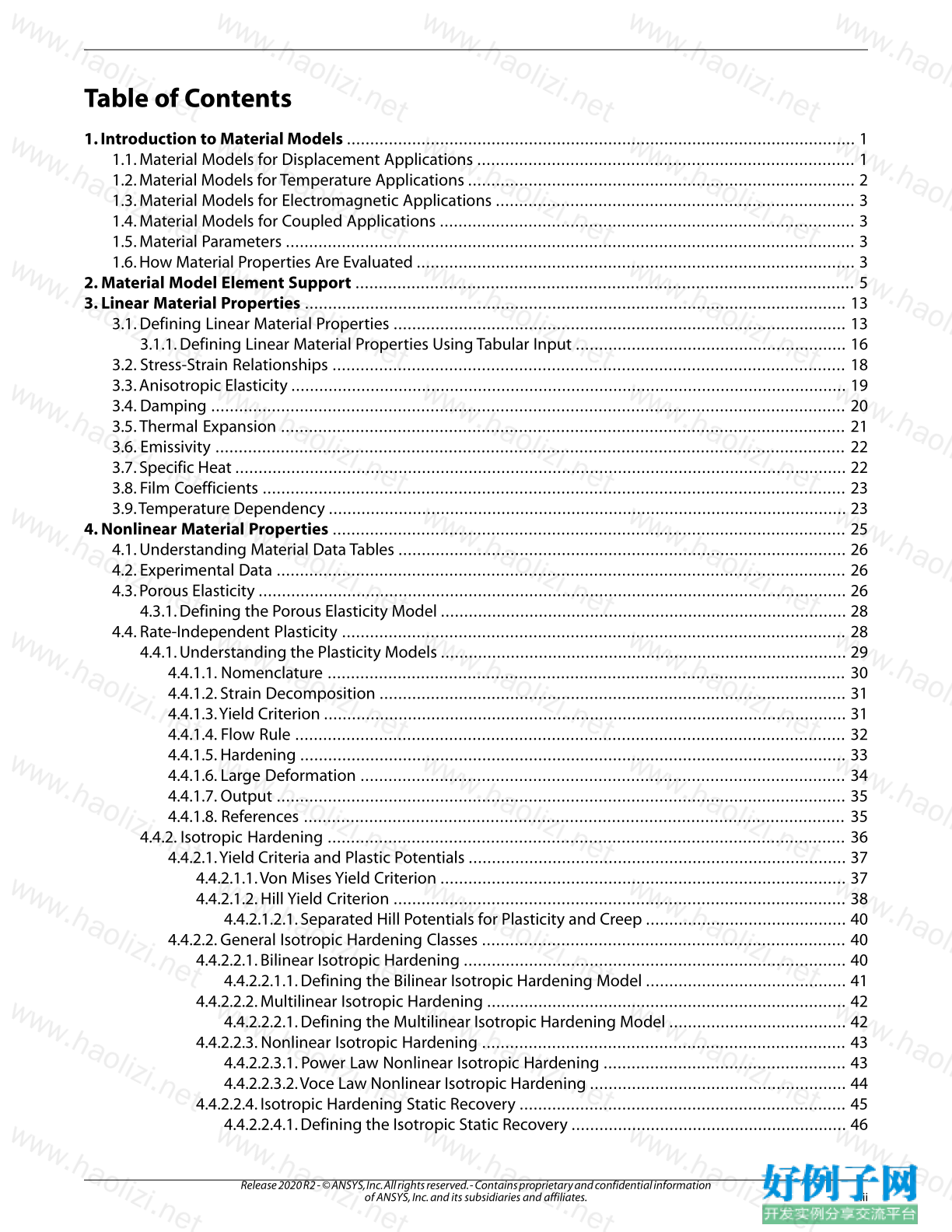
Table of Contents
1. Introduction to Material Models ............................................................................................................. 1
1.1. Material Models for Displacement Applications ................................................................................. 1
1.2. Material Models for Temperature Applications ................................................................................... 2
1.3. Material Models for Electromagnetic Applications ............................................................................. 3
1.4. Material Models for Coupled Applications ......................................................................................... 3
1.5. Material Parameters .......................................................................................................................... 3
1.6. How Material Properties Are Evaluated .............................................................................................. 3
2. Material Model Element Support ........................................................................................................... 5
3. Linear Material Properties .................................................................................................................... 13
3.1. Defining Linear Material Properties ................................................................................................. 13
3.1.1. Defining Linear Material Properties Using Tabular Input .......................................................... 16
3.2. Stress-Strain Relationships .............................................................................................................. 18
3.3. Anisotropic Elasticity ....................................................................................................................... 19
3.4. Damping ........................................................................................................................................ 20
3.5.Thermal Expansion ......................................................................................................................... 21
3.6. Emissivity ....................................................................................................................................... 22
3.7. Specific Heat ................................................................................................................................... 22
3.8. Film Coefficients ............................................................................................................................. 23
3.9.Temperature Dependency ............................................................................................................... 23
4. Nonlinear Material Properties .............................................................................................................. 25
4.1. Understanding Material Data Tables ................................................................................................ 26
4.2. Experimental Data .......................................................................................................................... 26
4.3. Porous Elasticity .............................................................................................................................. 26
4.3.1. Defining the Porous Elasticity Model ....................................................................................... 28
4.4. Rate-Independent Plasticity ............................................................................................................ 28
4.4.1. Understanding the Plasticity Models ....................................................................................... 29
4.4.1.1. Nomenclature ............................................................................................................... 30
4.4.1.2. Strain Decomposition .................................................................................................... 31
4.4.1.3.Yield Criterion ................................................................................................................ 31
4.4.1.4. Flow Rule ...................................................................................................................... 32
4.4.1.5. Hardening ..................................................................................................................... 33
4.4.1.6. Large Deformation ........................................................................................................ 34
4.4.1.7. Output .......................................................................................................................... 35
4.4.1.8. References .................................................................................................................... 35
4.4.2. Isotropic Hardening ............................................................................................................... 36
4.4.2.1.Yield Criteria and Plastic Potentials ................................................................................. 37
4.4.2.1.1.Von Mises Yield Criterion ....................................................................................... 37
4.4.2.1.2. Hill Yield Criterion ................................................................................................. 38
4.4.2.1.2.1. Separated Hill Potentials for Plasticity and Creep ........................................... 40
4.4.2.2. General Isotropic Hardening Classes .............................................................................. 40
4.4.2.2.1. Bilinear Isotropic Hardening .................................................................................. 40
4.4.2.2.1.1. Defining the Bilinear Isotropic Hardening Model ........................................... 41
4.4.2.2.2. Multilinear Isotropic Hardening ............................................................................. 42
4.4.2.2.2.1. Defining the Multilinear Isotropic Hardening Model ...................................... 42
4.4.2.2.3. Nonlinear Isotropic Hardening .............................................................................. 43
4.4.2.2.3.1. Power Law Nonlinear Isotropic Hardening .................................................... 43
4.4.2.2.3.2.Voce Law Nonlinear Isotropic Hardening ....................................................... 44
4.4.2.2.4. Isotropic Hardening Static Recovery ...................................................................... 45
4.4.2.2.4.1. Defining the Isotropic Static Recovery ........................................................... 46
iii
Release 2020 R2 - © ANSYS, Inc. All rights reserved. - Contains proprietary and confidential information
of ANSYS, Inc. and its subsidiaries and affiliates.
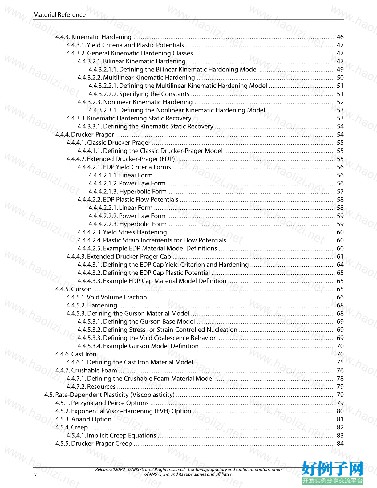
4.4.3. Kinematic Hardening ............................................................................................................. 46
4.4.3.1.Yield Criteria and Plastic Potentials ................................................................................. 47
4.4.3.2. General Kinematic Hardening Classes ............................................................................ 47
4.4.3.2.1. Bilinear Kinematic Hardening ................................................................................ 47
4.4.3.2.1.1. Defining the Bilinear Kinematic Hardening Model ......................................... 49
4.4.3.2.2. Multilinear Kinematic Hardening ........................................................................... 50
4.4.3.2.2.1. Defining the Multilinear Kinematic Hardening Model .................................... 51
4.4.3.2.2.2. Specifying the Constants .............................................................................. 51
4.4.3.2.3. Nonlinear Kinematic Hardening ............................................................................ 52
4.4.3.2.3.1. Defining the Nonlinear Kinematic Hardening Model ..................................... 53
4.4.3.3. Kinematic Hardening Static Recovery ............................................................................. 53
4.4.3.3.1. Defining the Kinematic Static Recovery ................................................................. 54
4.4.4. Drucker-Prager ....................................................................................................................... 54
4.4.4.1. Classic Drucker-Prager ................................................................................................... 55
4.4.4.1.1. Defining the Classic Drucker-Prager Model ............................................................ 55
4.4.4.2. Extended Drucker-Prager (EDP) ...................................................................................... 55
4.4.4.2.1. EDP Yield Criteria Forms ........................................................................................ 56
4.4.4.2.1.1. Linear Form .................................................................................................. 56
4.4.4.2.1.2. Power Law Form ........................................................................................... 56
4.4.4.2.1.3. Hyperbolic Form .......................................................................................... 57
4.4.4.2.2. EDP Plastic Flow Potentials .................................................................................... 58
4.4.4.2.2.1. Linear Form .................................................................................................. 58
4.4.4.2.2.2. Power Law Form ........................................................................................... 59
4.4.4.2.2.3. Hyperbolic Form .......................................................................................... 59
4.4.4.2.3.Yield Stress Hardening .......................................................................................... 60
4.4.4.2.4. Plastic Strain Increments for Flow Potentials .......................................................... 60
4.4.4.2.5. Example EDP Material Model Definitions ............................................................... 60
4.4.4.3. Extended Drucker-Prager Cap ........................................................................................ 61
4.4.4.3.1. Defining the EDP Cap Yield Criterion and Hardening .............................................. 64
4.4.4.3.2. Defining the EDP Cap Plastic Potential ................................................................... 65
4.4.4.3.3. Example EDP Cap Material Model Definition .......................................................... 65
4.4.5. Gurson ................................................................................................................................... 65
4.4.5.1.Void Volume Fraction ..................................................................................................... 66
4.4.5.2. Hardening ..................................................................................................................... 68
4.4.5.3. Defining the Gurson Material Model .............................................................................. 68
4.4.5.3.1. Defining the Gurson Base Model ........................................................................... 69
4.4.5.3.2. Defining Stress- or Strain-Controlled Nucleation .................................................... 69
4.4.5.3.3. Defining the Void Coalescence Behavior ............................................................... 69
4.4.5.3.4. Example Gurson Model Definition ......................................................................... 70
4.4.6. Cast Iron ................................................................................................................................ 70
4.4.6.1. Defining the Cast Iron Material Model ............................................................................ 75
4.4.7. Crushable Foam ..................................................................................................................... 76
4.4.7.1. Defining the Crushable Foam Material Model ................................................................. 78
4.4.7.2. Resources ...................................................................................................................... 79
4.5. Rate-Dependent Plasticity (Viscoplasticity) ...................................................................................... 79
4.5.1. Perzyna and Peirce Options .................................................................................................... 79
4.5.2. Exponential Visco-Hardening (EVH) Option ............................................................................. 80
4.5.3. Anand Option ........................................................................................................................ 81
4.5.4. Creep ..................................................................................................................................... 82
4.5.4.1. Implicit Creep Equations ................................................................................................ 83
4.5.5. Drucker-Prager Creep ............................................................................................................. 84
Release 2020 R2 - © ANSYS, Inc. All rights reserved. - Contains proprietary and confidential information
of ANSYS, Inc. and its subsidiaries and affiliates. iv
Material Reference
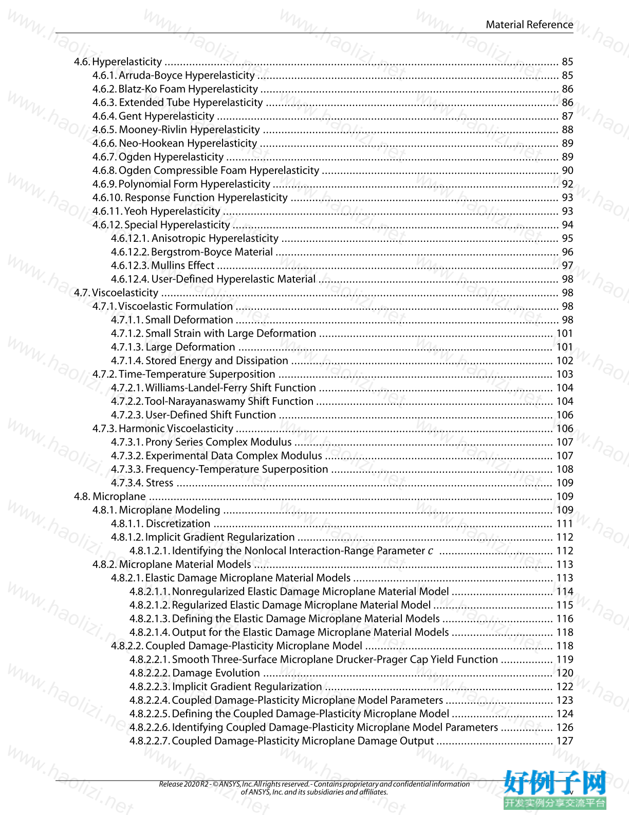
4.6. Hyperelasticity ................................................................................................................................ 85
4.6.1. Arruda-Boyce Hyperelasticity .................................................................................................. 85
4.6.2. Blatz-Ko Foam Hyperelasticity ................................................................................................. 86
4.6.3. Extended Tube Hyperelasticity ............................................................................................... 86
4.6.4. Gent Hyperelasticity ............................................................................................................... 87
4.6.5. Mooney-Rivlin Hyperelasticity ................................................................................................ 88
4.6.6. Neo-Hookean Hyperelasticity ................................................................................................. 89
4.6.7. Ogden Hyperelasticity ............................................................................................................ 89
4.6.8. Ogden Compressible Foam Hyperelasticity ............................................................................. 90
4.6.9. Polynomial Form Hyperelasticity ............................................................................................. 92
4.6.10. Response Function Hyperelasticity ....................................................................................... 93
4.6.11.Yeoh Hyperelasticity ............................................................................................................. 93
4.6.12. Special Hyperelasticity .......................................................................................................... 94
4.6.12.1. Anisotropic Hyperelasticity .......................................................................................... 95
4.6.12.2. Bergstrom-Boyce Material ............................................................................................ 96
4.6.12.3. Mullins Effect ............................................................................................................... 97
4.6.12.4. User-Defined Hyperelastic Material .............................................................................. 98
4.7.Viscoelasticity ................................................................................................................................. 98
4.7.1.Viscoelastic Formulation ......................................................................................................... 98
4.7.1.1. Small Deformation ......................................................................................................... 98
4.7.1.2. Small Strain with Large Deformation ............................................................................ 101
4.7.1.3. Large Deformation ...................................................................................................... 101
4.7.1.4. Stored Energy and Dissipation ..................................................................................... 102
4.7.2.Time-Temperature Superposition ......................................................................................... 103
4.7.2.1.Williams-Landel-Ferry Shift Function ............................................................................ 104
4.7.2.2.Tool-Narayanaswamy Shift Function ............................................................................. 104
4.7.2.3. User-Defined Shift Function ......................................................................................... 106
4.7.3. Harmonic Viscoelasticity ....................................................................................................... 106
4.7.3.1. Prony Series Complex Modulus .................................................................................... 107
4.7.3.2. Experimental Data Complex Modulus .......................................................................... 107
4.7.3.3. Frequency-Temperature Superposition ........................................................................ 108
4.7.3.4. Stress .......................................................................................................................... 109
4.8. Microplane ................................................................................................................................... 109
4.8.1. Microplane Modeling ........................................................................................................... 109
4.8.1.1. Discretization .............................................................................................................. 111
4.8.1.2. Implicit Gradient Regularization ................................................................................... 112
4.8.1.2.1. Identifying the Nonlocal Interaction-Range Parameter ..................................... 112
4.8.2. Microplane Material Models ................................................................................................. 113
4.8.2.1. Elastic Damage Microplane Material Models ................................................................. 113
4.8.2.1.1. Nonregularized Elastic Damage Microplane Material Model ................................. 114
4.8.2.1.2. Regularized Elastic Damage Microplane Material Model ....................................... 115
4.8.2.1.3. Defining the Elastic Damage Microplane Material Models .................................... 116
4.8.2.1.4. Output for the Elastic Damage Microplane Material Models ................................. 118
4.8.2.2. Coupled Damage-Plasticity Microplane Model ............................................................. 118
4.8.2.2.1. Smooth Three-Surface Microplane Drucker-Prager Cap Yield Function ................. 119
4.8.2.2.2. Damage Evolution .............................................................................................. 120
4.8.2.2.3. Implicit Gradient Regularization .......................................................................... 122
4.8.2.2.4. Coupled Damage-Plasticity Microplane Model Parameters ................................... 123
4.8.2.2.5. Defining the Coupled Damage-Plasticity Microplane Model ................................. 124
4.8.2.2.6. Identifying Coupled Damage-Plasticity Microplane Model Parameters ................. 126
4.8.2.2.7. Coupled Damage-Plasticity Microplane Damage Output ...................................... 127
v
Release 2020 R2 - © ANSYS, Inc. All rights reserved. - Contains proprietary and confidential information
of ANSYS, Inc. and its subsidiaries and affiliates.
Material Reference
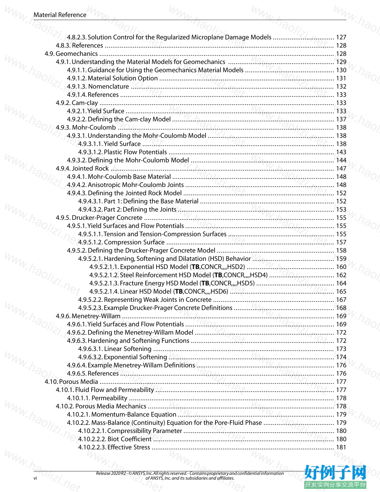
4.8.2.3. Solution Control for the Regularized Microplane Damage Models ................................. 127
4.8.3. References ........................................................................................................................... 128
4.9. Geomechanics .............................................................................................................................. 128
4.9.1. Understanding the Material Models for Geomechanics ......................................................... 129
4.9.1.1. Guidance for Using the Geomechanics Material Models ................................................ 130
4.9.1.2. Material Solution Option .............................................................................................. 131
4.9.1.3. Nomenclature ............................................................................................................. 132
4.9.1.4. References ................................................................................................................... 133
4.9.2. Cam-clay .............................................................................................................................. 133
4.9.2.1.Yield Surface ................................................................................................................ 133
4.9.2.2. Defining the Cam-clay Model ....................................................................................... 137
4.9.3. Mohr-Coulomb .................................................................................................................... 138
4.9.3.1. Understanding the Mohr-Coulomb Model .................................................................... 138
4.9.3.1.1.Yield Surface ....................................................................................................... 138
4.9.3.1.2. Plastic Flow Potentials ......................................................................................... 143
4.9.3.2. Defining the Mohr-Coulomb Model ............................................................................. 144
4.9.4. Jointed Rock ........................................................................................................................ 147
4.9.4.1. Mohr-Coulomb Base Material ....................................................................................... 148
4.9.4.2. Anisotropic Mohr-Coulomb Joints ................................................................................ 148
4.9.4.3. Defining the Jointed Rock Model ................................................................................. 152
4.9.4.3.1. Part 1: Defining the Base Material ........................................................................ 152
4.9.4.3.2. Part 2: Defining the Joints .................................................................................... 153
4.9.5. Drucker-Prager Concrete ...................................................................................................... 155
4.9.5.1.Yield Surfaces and Flow Potentials ................................................................................ 155
4.9.5.1.1.Tension and Tension-Compression Surfaces ......................................................... 155
4.9.5.1.2. Compression Surface .......................................................................................... 157
4.9.5.2. Defining the Drucker-Prager Concrete Model ............................................................... 158
4.9.5.2.1. Hardening, Softening and Dilatation (HSD) Behavior ............................................ 159
4.9.5.2.1.1. Exponential HSD Model (TB,CONCR,,,,HSD2) ............................................... 160
4.9.5.2.1.2. Steel Reinforcement HSD Model (TB,CONCR,,,,HSD4) ................................... 162
4.9.5.2.1.3. Fracture Energy HSD Model (TB,CONCR,,,,HSD5) .......................................... 164
4.9.5.2.1.4. Linear HSD Model (TB,CONCR,,,,HSD6) ........................................................ 165
4.9.5.2.2. Representing Weak Joints in Concrete ................................................................. 167
4.9.5.2.3. Example Drucker-Prager Concrete Definitions ...................................................... 168
4.9.6. Menetrey-Willam .................................................................................................................. 169
4.9.6.1.Yield Surfaces and Flow Potentials ................................................................................ 169
4.9.6.2. Defining the Menetrey-Willam Model ........................................................................... 172
4.9.6.3. Hardening and Softening Functions ............................................................................. 172
4.9.6.3.1. Linear Softening ................................................................................................. 173
4.9.6.3.2. Exponential Softening ......................................................................................... 174
4.9.6.4. Example Menetrey-Willam Definitions .......................................................................... 176
4.9.6.5. References ................................................................................................................... 176
4.10. Porous Media .............................................................................................................................. 177
4.10.1. Fluid Flow and Permeability ................................................................................................ 177
4.10.1.1. Permeability .............................................................................................................. 178
4.10.2. Porous Media Mechanics .................................................................................................... 178
4.10.2.1. Momentum-Balance Equation .................................................................................... 179
4.10.2.2. Mass-Balance (Continuity) Equation for the Pore-Fluid Phase ...................................... 179
4.10.2.2.1. Compressibility Parameter ................................................................................. 180
4.10.2.2.2. Biot Coefficient ................................................................................................. 180
4.10.2.2.3. Effective Stress .................................................................................................. 181
Release 2020 R2 - © ANSYS, Inc. All rights reserved. - Contains proprietary and confidential information
of ANSYS, Inc. and its subsidiaries and affiliates. vi
Material Reference
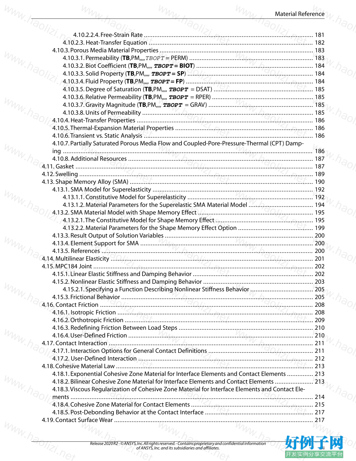
4.10.2.2.4. Free-Strain Rate ................................................................................................. 181
4.10.2.3. Heat-Transfer Equation .............................................................................................. 182
4.10.3. Porous Media Material Properties ........................................................................................ 183
4.10.3.1. Permeability (TB,PM,,,,TBOPT = PERM) ....................................................................... 183
4.10.3.2. Biot Coefficient (TB,PM,,,, TBOPT = BIOT) ................................................................... 184
4.10.3.3. Solid Property (TB,PM,,,, TBOPT = SP) ........................................................................ 184
4.10.3.4. Fluid Property (TB,PM,,,, TBOPT = FP) ......................................................................... 184
4.10.3.5. Degree of Saturation (TB,PM,,,, TBOPT = DSAT) ......................................................... 185
4.10.3.6. Relative Permeability (TB,PM,,,, TBOPT = RPER) .......................................................... 185
4.10.3.7. Gravity Magnitude (TB,PM,,,, TBOPT = GRAV) ............................................................ 185
4.10.3.8. Units of Permeability .................................................................................................. 185
4.10.4. Heat-Transfer Properties ..................................................................................................... 186
4.10.5.Thermal-Expansion Material Properties ............................................................................... 186
4.10.6.Transient vs. Static Analysis ................................................................................................. 186
4.10.7. Partially Saturated Porous Media Flow and Coupled-Pore-Pressure-Thermal (CPT) Damp-
ing ............................................................................................................................................... 186
4.10.8. Additional Resources .......................................................................................................... 187
4.11. Gasket ........................................................................................................................................ 187
4.12. Swelling ...................................................................................................................................... 189
4.13. Shape Memory Alloy (SMA) ......................................................................................................... 190
4.13.1. SMA Model for Superelasticity ............................................................................................ 192
4.13.1.1. Constitutive Model for Superelasticity ........................................................................ 192
4.13.1.2. Material Parameters for the Superelastic SMA Material Model ..................................... 194
4.13.2. SMA Material Model with Shape Memory Effect .................................................................. 195
4.13.2.1.The Constitutive Model for Shape Memory Effect ........................................................ 195
4.13.2.2. Material Parameters for the Shape Memory Effect Option ........................................... 199
4.13.3. Result Output of Solution Variables ..................................................................................... 200
4.13.4. Element Support for SMA ................................................................................................... 200
4.13.5. References ......................................................................................................................... 200
4.14. Multilinear Elasticity .................................................................................................................... 201
4.15. MPC184 Joint .............................................................................................................................. 202
4.15.1. Linear Elastic Stiffness and Damping Behavior ..................................................................... 202
4.15.2. Nonlinear Elastic Stiffness and Damping Behavior ............................................................... 203
4.15.2.1. Specifying a Function Describing Nonlinear Stiffness Behavior .................................... 205
4.15.3. Frictional Behavior .............................................................................................................. 205
4.16. Contact Friction .......................................................................................................................... 208
4.16.1. Isotropic Friction ................................................................................................................ 208
4.16.2. Orthotropic Friction ............................................................................................................ 209
4.16.3. Redefining Friction Between Load Steps ............................................................................. 210
4.16.4. User-Defined Friction .......................................................................................................... 210
4.17. Contact Interaction ..................................................................................................................... 211
4.17.1. Interaction Options for General Contact Definitions ............................................................ 211
4.17.2. User-Defined Interaction .................................................................................................... 212
4.18. Cohesive Material Law ................................................................................................................. 213
4.18.1. Exponential Cohesive Zone Material for Interface Elements and Contact Elements ............... 213
4.18.2. Bilinear Cohesive Zone Material for Interface Elements and Contact Elements ...................... 213
4.18.3.Viscous Regularization of Cohesive Zone Material for Interface Elements and Contact Ele-
ments ........................................................................................................................................... 214
4.18.4. Cohesive Zone Material for Contact Elements ...................................................................... 215
4.18.5. Post-Debonding Behavior at the Contact Interface .............................................................. 217
4.19. Contact Surface Wear .................................................................................................................. 217
vii
Release 2020 R2 - © ANSYS, Inc. All rights reserved. - Contains proprietary and confidential information
of ANSYS, Inc. and its subsidiaries and affiliates.
Material Reference
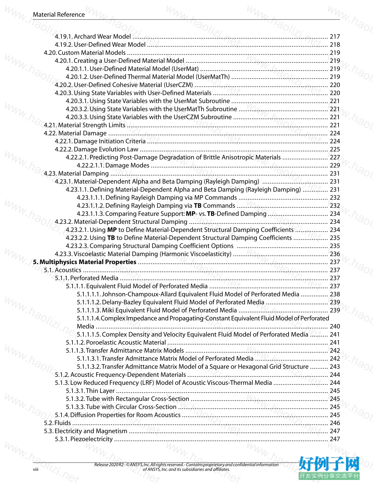
4.19.1. Archard Wear Model ........................................................................................................... 217
4.19.2. User-Defined Wear Model ................................................................................................... 218
4.20. Custom Material Models .............................................................................................................. 219
4.20.1. Creating a User-Defined Material Model .............................................................................. 219
4.20.1.1. User-Defined Material Model (UserMat) ...................................................................... 219
4.20.1.2. User-Defined Thermal Material Model (UserMatTh) ..................................................... 219
4.20.2. User-Defined Cohesive Material (UserCZM) ......................................................................... 220
4.20.3. Using State Variables with User-Defined Materials ............................................................... 220
4.20.3.1. Using State Variables with the UserMat Subroutine ..................................................... 221
4.20.3.2. Using State Variables with the UserMatTh Subroutine ................................................. 221
4.20.3.3. Using State Variables with the UserCZM Subroutine .................................................... 221
4.21. Material Strength Limits .............................................................................................................. 221
4.22. Material Damage ........................................................................................................................ 224
4.22.1. Damage Initiation Criteria ................................................................................................... 224
4.22.2. Damage Evolution Law ....................................................................................................... 225
4.22.2.1. Predicting Post-Damage Degradation of Brittle Anisotropic Materials ......................... 227
4.22.2.1.1. Damage Modes ................................................................................................. 229
4.23. Material Damping ....................................................................................................................... 231
4.23.1. Material-Dependent Alpha and Beta Damping (Rayleigh Damping) .................................... 231
4.23.1.1. Defining Material-Dependent Alpha and Beta Damping (Rayleigh Damping) .............. 231
4.23.1.1.1. Defining Rayleigh Damping via MP Commands ................................................. 232
4.23.1.1.2. Defining Rayleigh Damping via TB Commands .................................................. 232
4.23.1.1.3. Comparing Feature Support:MP- vs.TB-Defined Damping ................................. 234
4.23.2. Material-Dependent Structural Damping ............................................................................ 234
4.23.2.1. Using MP to Define Material-Dependent Structural Damping Coefficients .................. 234
4.23.2.2. Using TB to Define Material-Dependent Structural Damping Coefficients ................... 235
4.23.2.3. Comparing Structural Damping Coefficient Options .................................................. 235
4.23.3.Viscoelastic Material Damping (Harmonic Viscoelasticity) .................................................... 236
5. Multiphysics Material Properties ........................................................................................................ 237
5.1. Acoustics ...................................................................................................................................... 237
5.1.1. Perforated Media .................................................................................................................. 237
5.1.1.1. Equivalent Fluid Model of Perforated Media ................................................................. 237
5.1.1.1.1. Johnson-Champoux-Allard Equivalent Fluid Model of Perforated Media ............... 238
5.1.1.1.2. Delany-Bazley Equivalent Fluid Model of Perforated Media .................................. 239
5.1.1.1.3. Miki Equivalent Fluid Model of Perforated Media ................................................. 239
5.1.1.1.4. Complex Impedance and Propagating-Constant Equivalent Fluid Model of Perforated
Media ............................................................................................................................... 240
5.1.1.1.5. Complex Density and Velocity Equivalent Fluid Model of Perforated Media .......... 241
5.1.1.2. Poroelastic Acoustic Material ........................................................................................ 241
5.1.1.3.Transfer Admittance Matrix Models .............................................................................. 242
5.1.1.3.1.Transfer Admittance Matrix Model of Perforated Media ........................................ 242
5.1.1.3.2.Transfer Admittance Matrix Model of a Square or Hexagonal Grid Structure .......... 243
5.1.2. Acoustic Frequency-Dependent Materials ............................................................................. 244
5.1.3. Low Reduced Frequency (LRF) Model of Acoustic Viscous-Thermal Media .............................. 244
5.1.3.1.Thin Layer .................................................................................................................... 245
5.1.3.2.Tube with Rectangular Cross-Section ........................................................................... 245
5.1.3.3.Tube with Circular Cross-Section .................................................................................. 245
5.1.4. Diffusion Properties for Room Acoustics ................................................................................ 245
5.2. Fluids ............................................................................................................................................ 246
5.3. Electricity and Magnetism ............................................................................................................. 247
5.3.1. Piezoelectricity ..................................................................................................................... 247
Release 2020 R2 - © ANSYS, Inc. All rights reserved. - Contains proprietary and confidential information
of ANSYS, Inc. and its subsidiaries and affiliates. viii
Material Reference
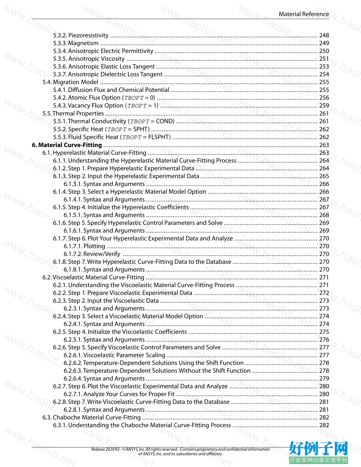
5.3.2. Piezoresistivity ..................................................................................................................... 248
5.3.3. Magnetism ........................................................................................................................... 249
5.3.4. Anisotropic Electric Permittivity ............................................................................................ 250
5.3.5. Anisotropic Viscosity ............................................................................................................ 251
5.3.6. Anisotropic Elastic Loss Tangent ........................................................................................... 253
5.3.7. Anisotropic Dielectric Loss Tangent ....................................................................................... 254
5.4. Migration Model ........................................................................................................................... 255
5.4.1. Diffusion Flux and Chemical Potential ................................................................................... 255
5.4.2. Atomic Flux Option (TBOPT = 0) ........................................................................................... 256
5.4.3.Vacancy Flux Option (TBOPT = 1) ......................................................................................... 259
5.5.Thermal Properties ........................................................................................................................ 261
5.5.1.Thermal Conductivity (TBOPT = COND) ................................................................................ 261
5.5.2. Specific Heat (TBOPT = SPHT) .............................................................................................. 262
5.5.3. Fluid Specific Heat (TBOPT = FLSPHT) .................................................................................. 262
6. Material Curve-Fitting ......................................................................................................................... 263
6.1. Hyperelastic Material Curve-Fitting ................................................................................................ 263
6.1.1. Understanding the Hyperelastic Material Curve-Fitting Process ............................................. 264
6.1.2. Step 1. Prepare Hyperelastic Experimental Data ..................................................................... 264
6.1.3. Step 2. Input the Hyperelastic Experimental Data .................................................................. 265
6.1.3.1. Syntax and Arguments ................................................................................................. 266
6.1.4. Step 3. Select a Hyperelastic Material Model Option .............................................................. 266
6.1.4.1. Syntax and Arguments ................................................................................................. 267
6.1.5. Step 4. Initialize the Hyperelastic Coefficients ........................................................................ 267
6.1.5.1. Syntax and Arguments ................................................................................................. 268
6.1.6. Step 5. Specify Hyperelastic Control Parameters and Solve ..................................................... 269
6.1.6.1. Syntax and Arguments ................................................................................................. 269
6.1.7. Step 6. Plot Your Hyperelastic Experimental Data and Analyze ............................................... 270
6.1.7.1. Plotting ....................................................................................................................... 270
6.1.7.2. Review/Verify .............................................................................................................. 270
6.1.8. Step 7.Write Hyperelastic Curve-Fitting Data to the Database ................................................ 270
6.1.8.1. Syntax and Arguments ................................................................................................. 270
6.2.Viscoelastic Material Curve-Fitting ................................................................................................. 271
6.2.1. Understanding the Viscoelastic Material Curve-Fitting Process .............................................. 271
6.2.2. Step 1. Prepare Viscoelastic Experimental Data ...................................................................... 272
6.2.3. Step 2. Input the Viscoelastic Data ......................................................................................... 273
6.2.3.1. Syntax and Arguments ................................................................................................. 273
6.2.4. Step 3. Select a Viscoelastic Material Model Option ................................................................ 274
6.2.4.1. Syntax and Arguments ................................................................................................. 274
6.2.5. Step 4. Initialize the Viscoelastic Coefficients ......................................................................... 275
6.2.5.1. Syntax and Arguments ................................................................................................. 276
6.2.6. Step 5. Specify Viscoelastic Control Parameters and Solve ...................................................... 277
6.2.6.1.Viscoelastic Parameter Scaling ..................................................................................... 277
6.2.6.2.Temperature-Dependent Solutions Using the Shift Function ......................................... 278
6.2.6.3.Temperature-Dependent Solutions Without the Shift Function ..................................... 278
6.2.6.4. Syntax and Arguments ................................................................................................. 279
6.2.7. Step 6. Plot the Viscoelastic Experimental Data and Analyze .................................................. 280
6.2.7.1. Analyze Your Curves for Proper Fit ................................................................................ 280
6.2.8. Step 7.Write Viscoelastic Curve-Fitting Data to the Database ................................................. 281
6.2.8.1. Syntax and Arguments ................................................................................................. 281
6.3. Chaboche Material Curve-Fitting ................................................................................................... 282
6.3.1. Understanding the Chaboche Material Curve-Fitting Process ................................................ 282
ix
Release 2020 R2 - © ANSYS, Inc. All rights reserved. - Contains proprietary and confidential information
of ANSYS, Inc. and its subsidiaries and affiliates.
Material Reference
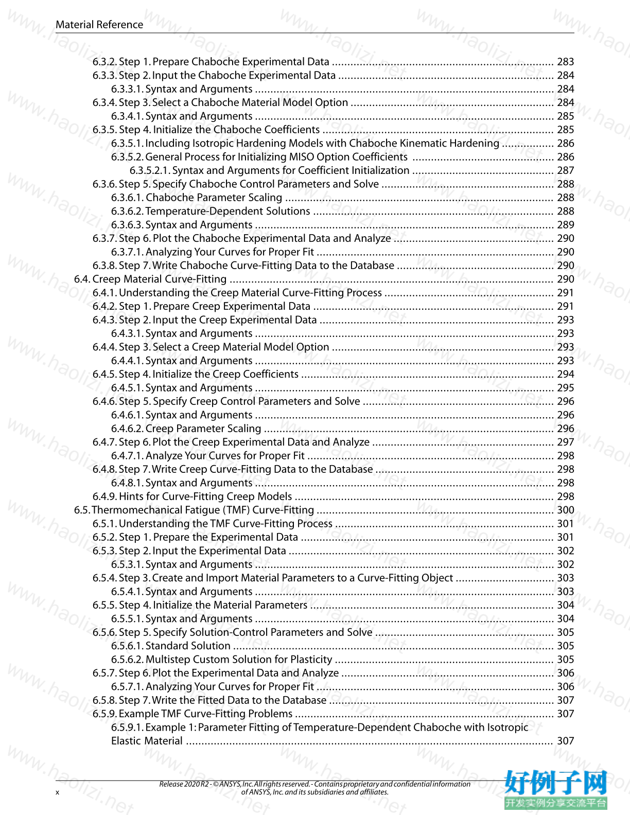
6.3.2. Step 1. Prepare Chaboche Experimental Data ........................................................................ 283
6.3.3. Step 2. Input the Chaboche Experimental Data ...................................................................... 284
6.3.3.1. Syntax and Arguments ................................................................................................. 284
6.3.4. Step 3. Select a Chaboche Material Model Option .................................................................. 284
6.3.4.1. Syntax and Arguments ................................................................................................. 285
6.3.5. Step 4. Initialize the Chaboche Coefficients ........................................................................... 285
6.3.5.1. Including Isotropic Hardening Models with Chaboche Kinematic Hardening ................. 286
6.3.5.2. General Process for Initializing MISO Option Coefficients .............................................. 286
6.3.5.2.1. Syntax and Arguments for Coefficient Initialization .............................................. 287
6.3.6. Step 5. Specify Chaboche Control Parameters and Solve ........................................................ 288
6.3.6.1. Chaboche Parameter Scaling ....................................................................................... 288
6.3.6.2.Temperature-Dependent Solutions .............................................................................. 288
6.3.6.3. Syntax and Arguments ................................................................................................. 289
6.3.7. Step 6. Plot the Chaboche Experimental Data and Analyze .................................................... 290
6.3.7.1. Analyzing Your Curves for Proper Fit ............................................................................. 290
6.3.8. Step 7.Write Chaboche Curve-Fitting Data to the Database ................................................... 290
6.4. Creep Material Curve-Fitting ......................................................................................................... 290
6.4.1. Understanding the Creep Material Curve-Fitting Process ....................................................... 291
6.4.2. Step 1. Prepare Creep Experimental Data .............................................................................. 291
6.4.3. Step 2. Input the Creep Experimental Data ............................................................................ 293
6.4.3.1. Syntax and Arguments ................................................................................................. 293
6.4.4. Step 3. Select a Creep Material Model Option ........................................................................ 293
6.4.4.1. Syntax and Arguments ................................................................................................. 293
6.4.5. Step 4. Initialize the Creep Coefficients .................................................................................. 294
6.4.5.1. Syntax and Arguments ................................................................................................. 295
6.4.6. Step 5. Specify Creep Control Parameters and Solve .............................................................. 296
6.4.6.1. Syntax and Arguments ................................................................................................. 296
6.4.6.2. Creep Parameter Scaling .............................................................................................. 296
6.4.7. Step 6. Plot the Creep Experimental Data and Analyze ........................................................... 297
6.4.7.1. Analyze Your Curves for Proper Fit ................................................................................ 298
6.4.8. Step 7.Write Creep Curve-Fitting Data to the Database .......................................................... 298
6.4.8.1. Syntax and Arguments ................................................................................................. 298
6.4.9. Hints for Curve-Fitting Creep Models .................................................................................... 298
6.5.Thermomechanical Fatigue (TMF) Curve-Fitting ............................................................................. 300
6.5.1. Understanding the TMF Curve-Fitting Process ....................................................................... 301
6.5.2. Step 1. Prepare the Experimental Data .................................................................................. 301
6.5.3. Step 2. Input the Experimental Data ...................................................................................... 302
6.5.3.1. Syntax and Arguments ................................................................................................. 302
6.5.4. Step 3. Create and Import Material Parameters to a Curve-Fitting Object ................................ 303
6.5.4.1. Syntax and Arguments ................................................................................................. 303
6.5.5. Step 4. Initialize the Material Parameters ............................................................................... 304
6.5.5.1. Syntax and Arguments ................................................................................................. 304
6.5.6. Step 5. Specify Solution-Control Parameters and Solve .......................................................... 305
6.5.6.1. Standard Solution ........................................................................................................ 305
6.5.6.2. Multistep Custom Solution for Plasticity ....................................................................... 305
6.5.7. Step 6. Plot the Experimental Data and Analyze ..................................................................... 306
6.5.7.1. Analyzing Your Curves for Proper Fit ............................................................................. 306
6.5.8. Step 7.Write the Fitted Data to the Database ......................................................................... 307
6.5.9. Example TMF Curve-Fitting Problems .................................................................................... 307
6.5.9.1. Example 1: Parameter Fitting of Temperature-Dependent Chaboche with Isotropic
Elastic Material ....................................................................................................................... 307
Release 2020 R2 - © ANSYS, Inc. All rights reserved. - Contains proprietary and confidential information
of ANSYS, Inc. and its subsidiaries and affiliates. x
Material Reference
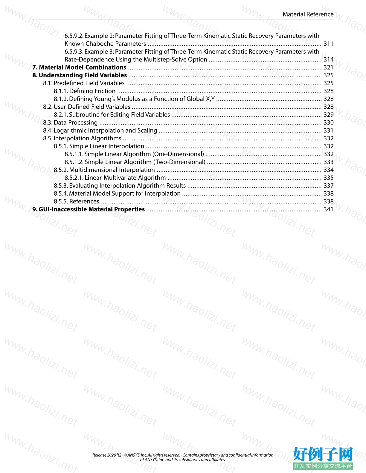
6.5.9.2. Example 2: Parameter Fitting of Three-Term Kinematic Static Recovery Parameters with
Known Chaboche Parameters ................................................................................................. 311
6.5.9.3. Example 3: Parameter Fitting of Three-Term Kinematic Static Recovery Parameters with
Rate-Dependence Using the Multistep-Solve Option ............................................................... 314
7. Material Model Combinations ............................................................................................................ 321
8. Understanding Field Variables ............................................................................................................ 325
8.1. Predefined Field Variables ............................................................................................................. 325
8.1.1. Defining Friction .................................................................................................................. 328
8.1.2. Defining Young’s Modulus as a Function of Global X,Y ........................................................... 328
8.2. User-Defined Field Variables .......................................................................................................... 328
8.2.1. Subroutine for Editing Field Variables .................................................................................... 329
8.3. Data Processing ............................................................................................................................ 330
8.4. Logarithmic Interpolation and Scaling ........................................................................................... 331
8.5. Interpolation Algorithms ............................................................................................................... 332
8.5.1. Simple Linear Interpolation .................................................................................................. 332
8.5.1.1. Simple Linear Algorithm (One-Dimensional) ................................................................. 332
8.5.1.2. Simple Linear Algorithm (Two-Dimensional) ................................................................ 333
8.5.2. Multidimensional Interpolation ............................................................................................ 334
8.5.2.1. Linear-Multivariate Algorithm ...................................................................................... 335
8.5.3. Evaluating Interpolation Algorithm Results ........................................................................... 337
8.5.4. Material Model Support for Interpolation .............................................................................. 338
8.5.5. References ........................................................................................................................... 338
9. GUI-Inaccessible Material Properties .................................................................................................. 341
小贴士
感谢您为本站写下的评论,您的评论对其它用户来说具有重要的参考价值,所以请认真填写。
- 类似“顶”、“沙发”之类没有营养的文字,对勤劳贡献的楼主来说是令人沮丧的反馈信息。
- 相信您也不想看到一排文字/表情墙,所以请不要反馈意义不大的重复字符,也请尽量不要纯表情的回复。
- 提问之前请再仔细看一遍楼主的说明,或许是您遗漏了。
- 请勿到处挖坑绊人、招贴广告。既占空间让人厌烦,又没人会搭理,于人于己都无利。
关于好例子网
本站旨在为广大IT学习爱好者提供一个非营利性互相学习交流分享平台。本站所有资源都可以被免费获取学习研究。本站资源来自网友分享,对搜索内容的合法性不具有预见性、识别性、控制性,仅供学习研究,请务必在下载后24小时内给予删除,不得用于其他任何用途,否则后果自负。基于互联网的特殊性,平台无法对用户传输的作品、信息、内容的权属或合法性、安全性、合规性、真实性、科学性、完整权、有效性等进行实质审查;无论平台是否已进行审查,用户均应自行承担因其传输的作品、信息、内容而可能或已经产生的侵权或权属纠纷等法律责任。本站所有资源不代表本站的观点或立场,基于网友分享,根据中国法律《信息网络传播权保护条例》第二十二与二十三条之规定,若资源存在侵权或相关问题请联系本站客服人员,点此联系我们。关于更多版权及免责申明参见 版权及免责申明


网友评论
我要评论