
实例介绍
【实例简介】
【实例截图】
【核心代码】
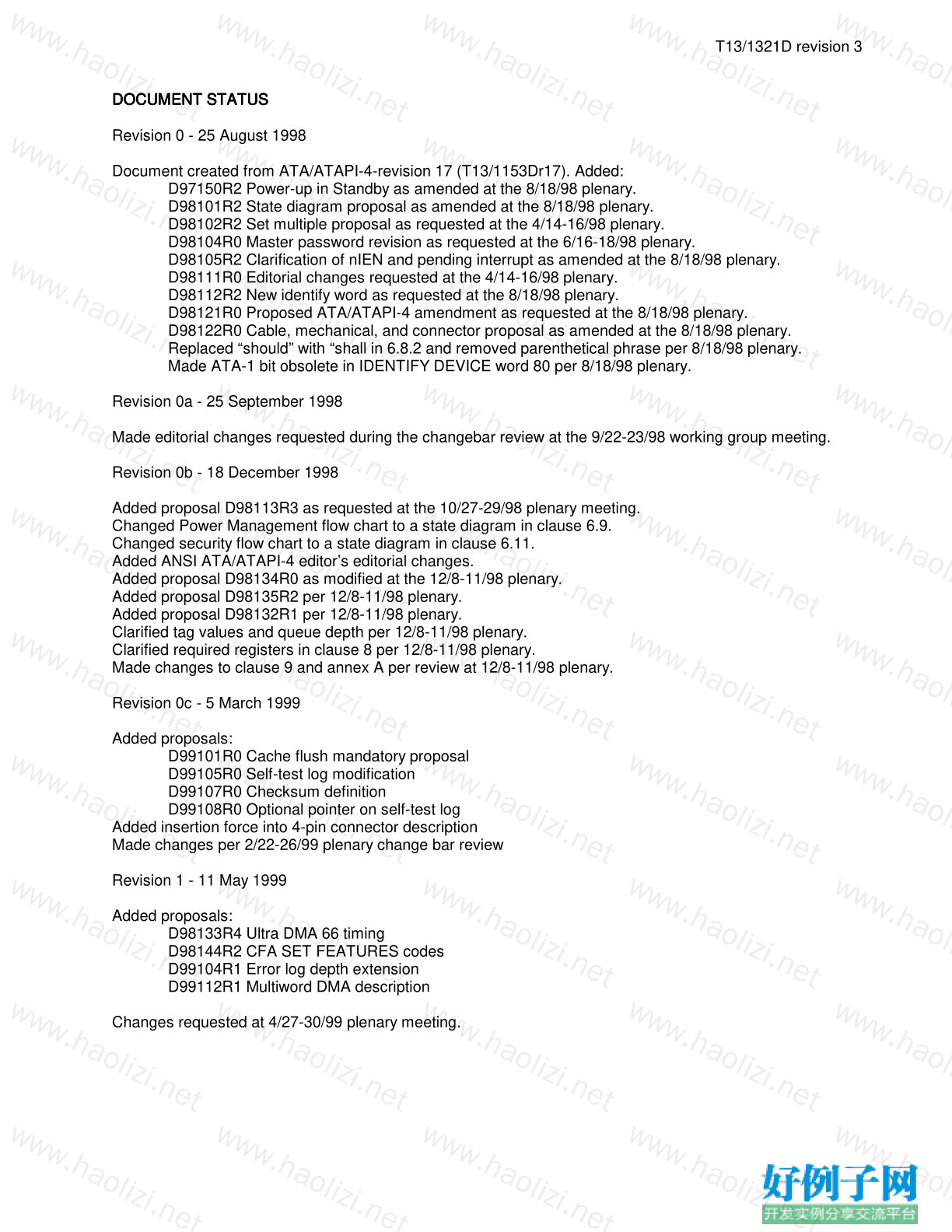
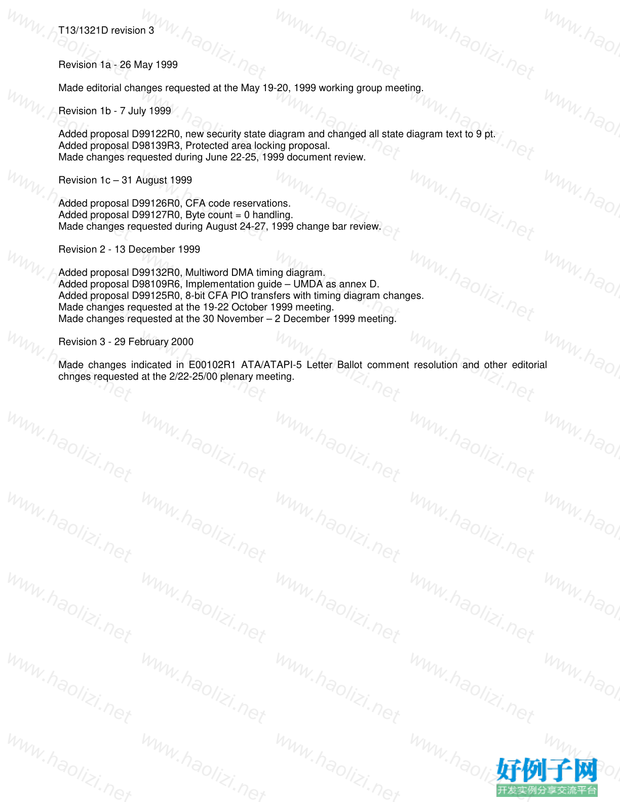
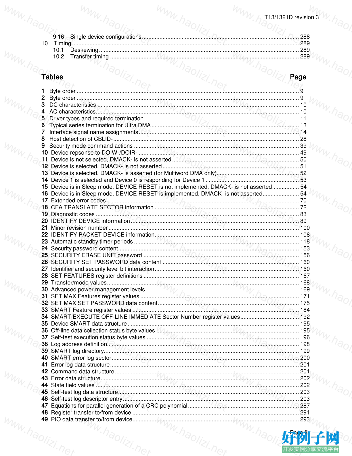
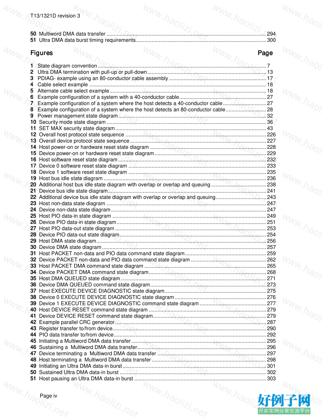
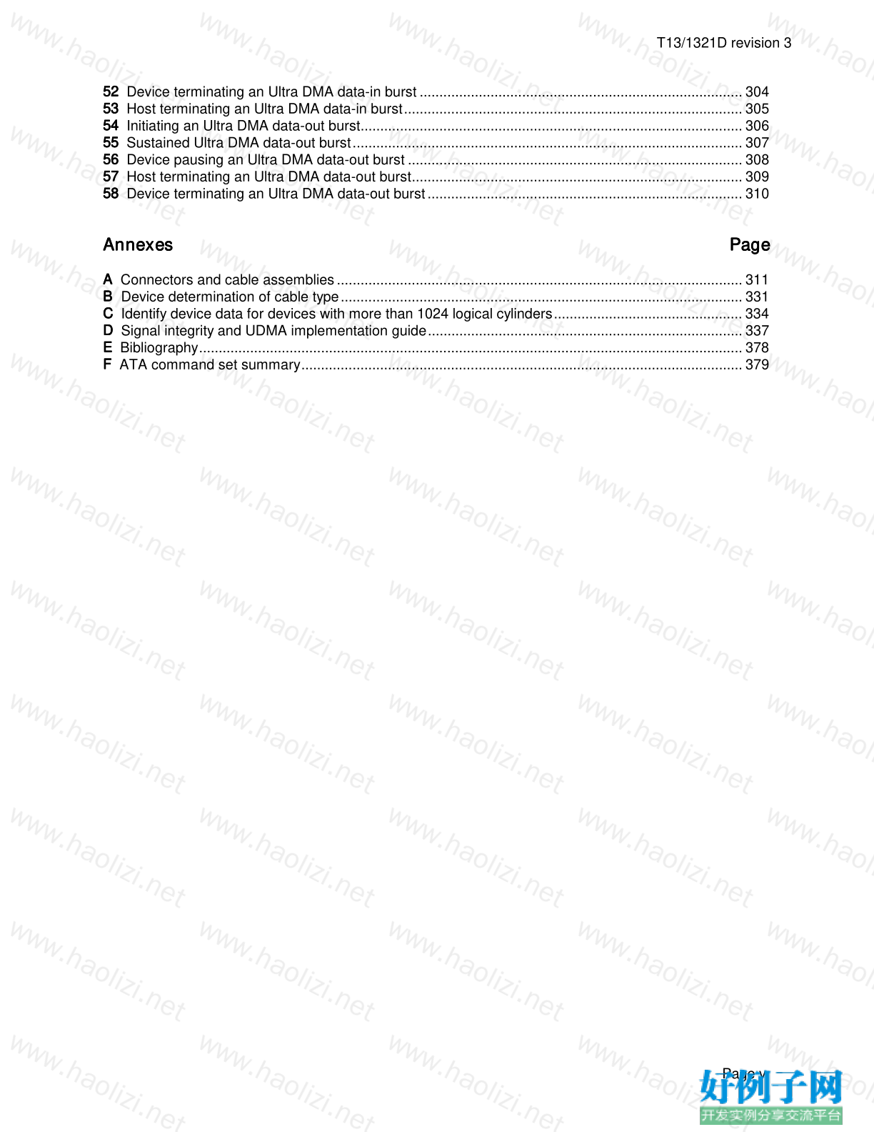
Contents Page
Foreword................................................................................................................................................... vi
Introduction............................................................................................................................................... viii
1 Scope................................................................................................................................................ 1
2 Normative references ....................................................................................................................... 1
2.1 Approved references .............................................................................................................. 1
2.2 References under development ............................................................................................. 2
2.3 Other references .................................................................................................................... 2
3 Definitions, abbreviations, and conventions...................................................................................... 2
3.1 Definitions and abbreviations ................................................................................................. 2
3.2 Conventions............................................................................................................................ 5
4 Interface physical and electrical requirements.................................................................................. 9
4.1 Cable configuration................................................................................................................. 9
4.2 Electrical characteristics......................................................................................................... 10
5 Interface signal assignments and descriptions................................................................................. 13
5.1 Signal summary...................................................................................................................... 13
5.2 Signal descriptions ................................................................................................................. 14
6 General operational requirements .................................................................................................... 19
6.1 Command delivery.................................................................................................................. 19
6.2 Register delivered data transfer command sector addressing............................................... 19
6.3 Interrupts ................................................................................................................................ 21
6.4 General feature set................................................................................................................. 21
6.5 Multiword DMA ....................................................................................................................... 23
6.6 Ultra DMA feature set............................................................................................................. 24
6.7 Host determination of cable type by detecting CBLID-........................................................... 26
6.8 PACKET Command feature set ............................................................................................. 28
6.9 Overlapped feature set........................................................................................................... 29
6.10 Queued feature set................................................................................................................. 30
6.11 Power Management feature set ............................................................................................. 31
6.12 Advanced Power Management feature set ............................................................................ 34
6.13 Security Mode feature set....................................................................................................... 34
6.14 Self-monitoring, analysis, and reporting technology feature set............................................. 39
6.15 Host Protected Area feature set ............................................................................................. 41
6.16 CFA feature set ...................................................................................................................... 45
6.17 Removable Media Status Notification and Removable Media feature sets............................ 45
6.18 Power-Up In Standby feature set ........................................................................................... 47
7 Interface register definitions and descriptions .................................................................................. 48
7.1 Device addressing considerations.......................................................................................... 48
7.2 I/O register descriptions.......................................................................................................... 54
7.3 Alternate Status register......................................................................................................... 55
7.4 Command register.................................................................................................................. 55
7.5 Cylinder High register ............................................................................................................. 56
7.6 Cylinder Low register.............................................................................................................. 56
7.7 Data port................................................................................................................................. 57
7.8 Data register........................................................................................................................... 58
7.9 Device Control register........................................................................................................... 58
7.10 Device/Head register.............................................................................................................. 59
7.11 Error register........................................................................................................................... 60
7.12 Features register .................................................................................................................... 61
7.13 Sector Count register.............................................................................................................. 61
7.14 Sector Number register .......................................................................................................... 62
7.15 Status register ........................................................................................................................ 62
8 Command descriptions..................................................................................................................... 65
8.1 CFA ERASE SECTORS......................................................................................................... 66
8.2 CFA REQUEST EXTENDED ERROR CODE........................................................................ 68
8.3 CFA TRANSLATE SECTOR .................................................................................................. 71
8.4 CFA WRITE MULTIPLE WITHOUT ERASE.......................................................................... 73
8.5 CFA WRITE SECTORS WITHOUT ERASE.......................................................................... 75
T13/1321D revision 3
Page ii
8.6 CHECK POWER MODE......................................................................................................... 77
8.7 DEVICE RESET ..................................................................................................................... 78
8.8 DOWNLOAD MICROCODE................................................................................................... 80
8.9 EXECUTE DEVICE DIAGNOSTIC......................................................................................... 81
8.10 FLUSH CACHE ...................................................................................................................... 83
8.11 GET MEDIA STATUS............................................................................................................. 85
8.12 IDENTIFY DEVICE ................................................................................................................. 87
8.13 IDENTIFY PACKET DEVICE.................................................................................................. 105
8.14 IDLE........................................................................................................................................ 117
8.15 IDLE IMMEDIATE................................................................................................................... 119
8.16 INITIALIZE DEVICE PARAMETERS...................................................................................... 120
8.17 MEDIA EJECT ........................................................................................................................ 123
8.18 MEDIA LOCK.......................................................................................................................... 124
8.19 MEDIA UNLOCK .................................................................................................................... 126
8.20 NOP ........................................................................................................................................ 128
8.21 PACKET ................................................................................................................................. 130
8.22 READ BUFFER ...................................................................................................................... 135
8.23 READ DMA............................................................................................................................. 137
8.24 READ DMA QUEUED ............................................................................................................ 139
8.25 READ MULTIPLE ................................................................................................................... 142
8.26 READ NATIVE MAX ADDRESS............................................................................................. 145
8.27 READ SECTOR(S)................................................................................................................. 147
8.28 READ VERIFY SECTOR(S)................................................................................................... 149
8.29 SECURITY DISABLE PASSWORD ....................................................................................... 151
8.30 SECURITY ERASE PREPARE .............................................................................................. 153
8.31 SECURITY ERASE UNIT ....................................................................................................... 154
8.32 SECURITY FREEZE LOCK.................................................................................................... 156
8.33 SECURITY SET PASSWORD ............................................................................................... 158
8.34 SECURITY UNLOCK.............................................................................................................. 160
8.35 SEEK ...................................................................................................................................... 162
8.36 SERVICE ................................................................................................................................ 164
8.37 SET FEATURES..................................................................................................................... 165
8.38 SET MAX ................................................................................................................................ 170
8.39 SET MULTIPLE MODE .......................................................................................................... 180
8.40 SLEEP .................................................................................................................................... 182
8.41 SMART ................................................................................................................................... 184
8.42 STANDBY............................................................................................................................... 209
8.43 STANDBY IMMEDIATE.......................................................................................................... 211
8.44 WRITE BUFFER..................................................................................................................... 213
8.45 WRITE DMA........................................................................................................................... 214
8.46 WRITE DMA QUEUED........................................................................................................... 216
8.47 WRITE MULTIPLE ................................................................................................................. 220
8.48 WRITE SECTOR(S) ............................................................................................................... 223
9 Protocol............................................................................................................................................. 225
9.1 Power-on and hardware reset protocol................................................................................... 228
9.2 Software reset protocol........................................................................................................... 232
9.3 Bus idle protocol ..................................................................................................................... 236
9.4 Non-data command protocol .................................................................................................. 246
9.5 PIO data-in command protocol............................................................................................... 248
9.6 PIO data-out command protocol............................................................................................. 252
9.7 DMA command protocol ......................................................................................................... 255
9.8 PACKET command protocol................................................................................................... 258
9.9 READ/WRITE DMA QUEUED command protocol................................................................. 270
9.10 EXECUTE DEVICE DIAGNOSTIC command protocol .......................................................... 274
9.11 DEVICE RESET command protocol....................................................................................... 278
9.12 Signature and persistence...................................................................................................... 280
9.13 Ultra DMA data-in commands ................................................................................................ 281
9.14 Ultra DMA data-out commands .............................................................................................. 283
9.15 Ultra DMA CRC rules.............................................................................................................. 286
T13/1321D revision 3
Page iii
9.16 Single device configurations................................................................................................... 288
10 Timing ............................................................................................................................................... 289
10.1 Deskewing.............................................................................................................................. 289
10.2 Transfer timing ....................................................................................................................... 289
Tables Page
1 Byte order ............................................................................................................................................ 9
2 Byte order ............................................................................................................................................ 9
3 DC characteristics ............................................................................................................................... 10
4 AC characteristics................................................................................................................................ 10
5 Driver types and required termination.................................................................................................. 11
6 Typical series termination for Ultra DMA ............................................................................................. 13
7 Interface signal name assignments..................................................................................................... 14
8 Host detection of CBLID-..................................................................................................................... 28
9 Security mode command actions ........................................................................................................ 39
10 Device repsonse to DOIW-/DOIR- ..................................................................................................... 49
11 Device is not selected, DMACK- is not asserted ................................................................................ 50
12 Device is selected, DMACK- is not asserted ...................................................................................... 51
13 Device is selected, DMACK- is asserted (for Multiword DMA only).................................................... 52
14 Device 1 is selected and Device 0 is responding for Device 1 ........................................................... 53
15 Device is in Sleep mode, DEVICE RESET is not implemented, DMACK- is not asserted................. 54
16 Device is in Sleep mode, DEVICE RESET is implemented, DMACK- is not asserted....................... 54
17 Extended error codes ......................................................................................................................... 70
18 CFA TRANSLATE SECTOR information ........................................................................................... 72
19 Diagnostic codes ................................................................................................................................ 83
20 IDENTIFY DEVICE information .......................................................................................................... 89
21 Minor revision number ........................................................................................................................ 100
22 IDENTIFY PACKET DEVICE information........................................................................................... 108
23 Automatic standby timer periods ........................................................................................................ 118
24 Security password content.................................................................................................................. 153
25 SECURITY ERASE UNIT password .................................................................................................. 156
26 SECURITY SET PASSWORD data content ...................................................................................... 160
27 Identifier and security level bit interaction........................................................................................... 160
28 SET FEATURES register definitions .................................................................................................. 167
29 Transfer/mode values......................................................................................................................... 168
30 Advanced power management levels................................................................................................. 169
31 SET MAX Features register values .................................................................................................... 171
32 SET MAX SET PASSWORD data content......................................................................................... 175
33 SMART Feature register values ......................................................................................................... 184
34 SMART EXECUTE OFF-LINE IMMEDIATE Sector Number register values..................................... 192
35 Device SMART data structure ............................................................................................................ 195
36 Off-line data collection status byte values .......................................................................................... 195
37 Self-test execution status byte values ................................................................................................ 196
38 Log address definition......................................................................................................................... 198
39 SMART log directory........................................................................................................................... 199
40 SMART error log sector...................................................................................................................... 200
41 Error log data structure....................................................................................................................... 201
42 Command data structure.................................................................................................................... 201
43 Error data structure............................................................................................................................. 202
44 State field values ................................................................................................................................ 202
45 Self-test log data structure.................................................................................................................. 203
46 Self-test log descriptor entry............................................................................................................... 203
47 Equations for parallel generation of a CRC polynomial...................................................................... 287
48 Register transfer to/from device ......................................................................................................... 291
49 PIO data transfer to/from device......................................................................................................... 293
T13/1321D revision 3
Page iv
50 Multiword DMA data transfer .............................................................................................................. 294
51 Ultra DMA data burst timing requirements.......................................................................................... 300
Figures Page
1 State diagram convention .................................................................................................................... 7
2 Ultra DMA termination with pull-up or pull-down.................................................................................. 13
3 PDIAG- example using an 80-conductor cable assembly ................................................................... 17
4 Cable select example .......................................................................................................................... 18
5 Alternate cable select example............................................................................................................ 18
6 Example configuration of a system with a 40-conductor cable............................................................ 27
7 Example configuration of a system where the host detects a 40-conductor cable.............................. 27
8 Example configuration of a system where the host detects an 80-conductor cable............................ 28
9 Power management state diagram...................................................................................................... 32
10 Security mode state diagram .............................................................................................................. 36
11 SET MAX security state diagram........................................................................................................ 43
12 Overall host protocol state sequence ................................................................................................. 226
13 Overall device protocol state sequence.............................................................................................. 227
14 Host power-on or hardware reset state diagram ................................................................................ 228
15 Device power-on or hardware reset state diagram............................................................................. 229
16 Host software reset state diagram ...................................................................................................... 232
17 Device 0 software reset state diagram ............................................................................................... 233
18 Device 1 software reset state diagram ............................................................................................... 235
19 Host bus idle state diagram ................................................................................................................ 236
20 Additional host bus idle state diagram with overlap or overlap and queuing ...................................... 238
21 Device bus idle state diagram............................................................................................................. 241
22 Additional device bus idle state diagram with overlap or overlap and queuing................................... 243
23 Host non-data state diagram .............................................................................................................. 247
24 Device non-data state diagram........................................................................................................... 247
25 Host PIO data-in state diagram .......................................................................................................... 249
26 Device PIO data-in state diagram....................................................................................................... 251
27 Host PIO data-out state diagram ........................................................................................................ 253
28 Device PIO data-out state diagram..................................................................................................... 254
29 Host DMA state diagram..................................................................................................................... 256
30 Device DMA state diagram ................................................................................................................. 257
31 Host PACKET non-data and PIO data command state diagram........................................................ 259
32 Device PACKET non-data and PIO data command state diagram .................................................... 262
33 Host PACKET DMA command state diagram .................................................................................... 265
34 Device PACKET DMA command state diagram................................................................................. 268
35 Host DMA QUEUED state diagram .................................................................................................... 271
36 Device DMA QUEUED command state diagram................................................................................ 273
37 Host EXECUTE DEVICE DIAGNOSTIC state diagram...................................................................... 275
38 Device 0 EXECUTE DEVICE DIAGNOSTIC state diagram ............................................................... 276
39 Device 1 EXECUTE DEVICE DIAGNOSTIC command state diagram .............................................. 277
40 Host DEVICE RESET command state diagram ................................................................................. 279
41 Device DEVICE RESET command state diagram.............................................................................. 279
42 Example parallel CRC generator ........................................................................................................ 287
43 Register transfer to/from device.......................................................................................................... 290
44 PIO data transfer to/from device......................................................................................................... 292
45 Initiating a Multiword DMA data transfer............................................................................................. 295
46 Sustaining a Multiword DMA data transfer......................................................................................... 296
47 Device terminating a Multiword DMA data transfer ........................................................................... 297
48 Host terminating a Multiword DMA data transfer ............................................................................... 298
49 Initiating an Ultra DMA data-in burst................................................................................................... 301
50 Sustained Ultra DMA data-in burst ..................................................................................................... 302
51 Host pausing an Ultra DMA data-in burst ........................................................................................... 303
T13/1321D revision 3
Page v
52 Device terminating an Ultra DMA data-in burst .................................................................................. 304
53 Host terminating an Ultra DMA data-in burst...................................................................................... 305
54 Initiating an Ultra DMA data-out burst................................................................................................. 306
55 Sustained Ultra DMA data-out burst................................................................................................... 307
56 Device pausing an Ultra DMA data-out burst ..................................................................................... 308
57 Host terminating an Ultra DMA data-out burst.................................................................................... 309
58 Device terminating an Ultra DMA data-out burst ................................................................................ 310
Annexes Page Annexes Page
A Connectors and cable assemblies ....................................................................................................... 311
B Device determination of cable type...................................................................................................... 331
C Identify device data for devices with more than 1024 logical cylinders................................................ 334
D Signal integrity and UDMA implementation guide................................................................................ 337
E Bibliography.......................................................................................................................................... 378
F ATA command set summary................................................................................................................ 379
好例子网口号:伸出你的我的手 — 分享!
小贴士
感谢您为本站写下的评论,您的评论对其它用户来说具有重要的参考价值,所以请认真填写。
- 类似“顶”、“沙发”之类没有营养的文字,对勤劳贡献的楼主来说是令人沮丧的反馈信息。
- 相信您也不想看到一排文字/表情墙,所以请不要反馈意义不大的重复字符,也请尽量不要纯表情的回复。
- 提问之前请再仔细看一遍楼主的说明,或许是您遗漏了。
- 请勿到处挖坑绊人、招贴广告。既占空间让人厌烦,又没人会搭理,于人于己都无利。
关于好例子网
本站旨在为广大IT学习爱好者提供一个非营利性互相学习交流分享平台。本站所有资源都可以被免费获取学习研究。本站资源来自网友分享,对搜索内容的合法性不具有预见性、识别性、控制性,仅供学习研究,请务必在下载后24小时内给予删除,不得用于其他任何用途,否则后果自负。基于互联网的特殊性,平台无法对用户传输的作品、信息、内容的权属或合法性、安全性、合规性、真实性、科学性、完整权、有效性等进行实质审查;无论平台是否已进行审查,用户均应自行承担因其传输的作品、信息、内容而可能或已经产生的侵权或权属纠纷等法律责任。本站所有资源不代表本站的观点或立场,基于网友分享,根据中国法律《信息网络传播权保护条例》第二十二与二十三条之规定,若资源存在侵权或相关问题请联系本站客服人员,点此联系我们。关于更多版权及免责申明参见 版权及免责申明

网友评论
我要评论